Author: Arokiaraj Arputharaj

  • Ensuring Compliance with AS 1428.1 and BCA: Limiting Riser Openings to 125 mm in Commercial Staircases

    Ensuring Compliance with AS 1428.1 and BCA: Limiting Riser Openings to 125 mm in Commercial Staircases

    If you would like me to assist with your project, please send an email to koshy@tek1.com.au with your project specifications. Kindly use ‘Raj’ as the subject header.

    When performing detailed engineering for commercial staircases and balustrades, it’s essential to ensure that all aspects comply with AS 1428.1 and the relevant provisions from the Building Code of Australia (BCA), particularly those regarding accessibility and safety. Here’s a breakdown of the critical points you must address:

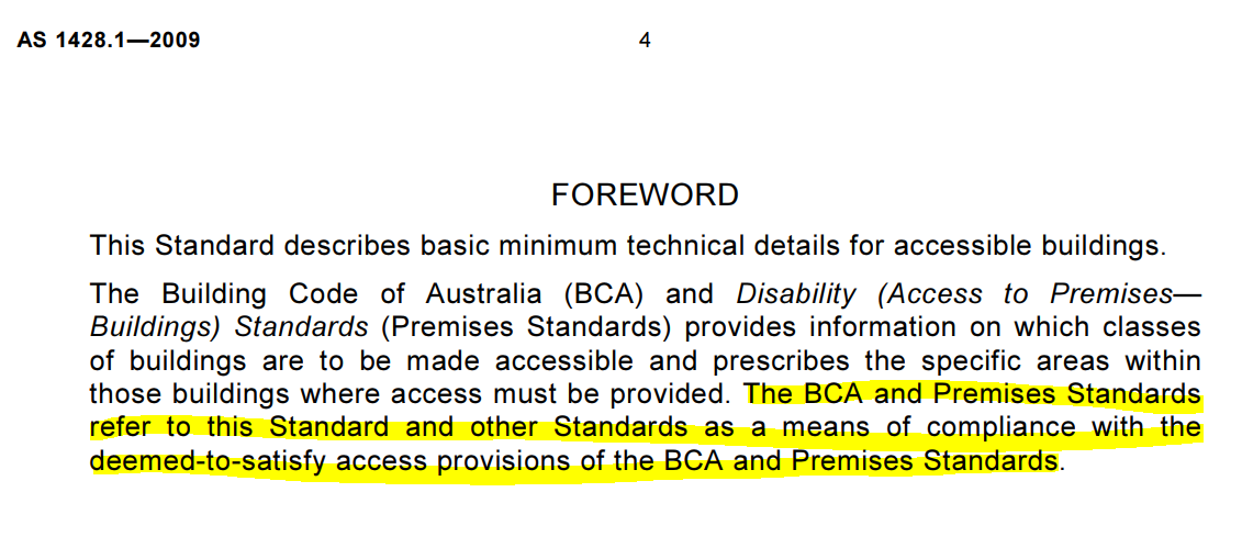
    Compliance with AS 1428.1:
    1. This standard outlines the minimum technical requirements for accessible buildings. Engineers must reference the BCA to align with safety and access provisions. AS 1428.1 directs engineers to follow BCA for detailed requirements related to stair and balustrade design, ensuring all safety standards are met, particularly for disabled access.

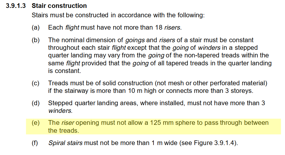
    2. BCA 3.9.1.3 – Riser Opening Requirement:
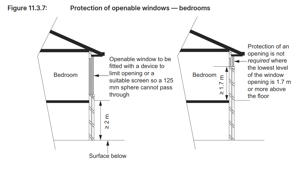
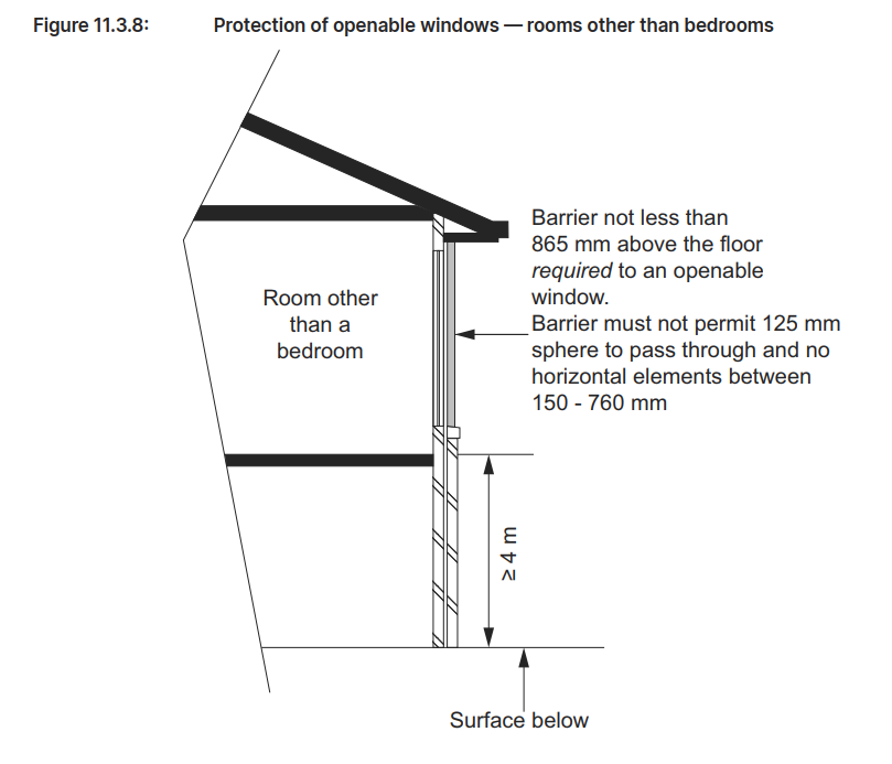
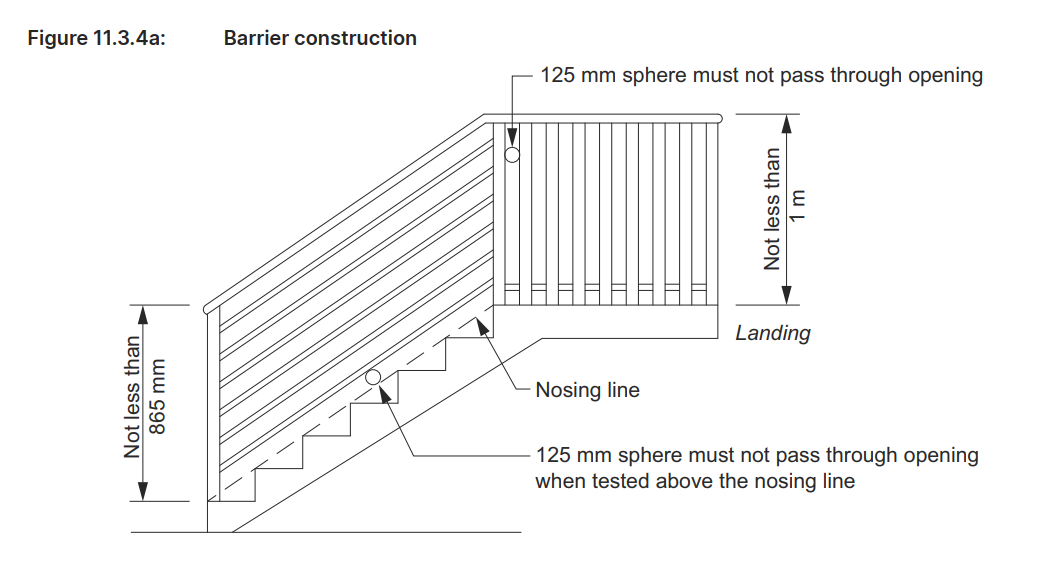
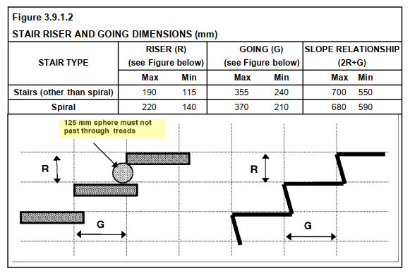
    One of the key safety provisions under BCA 3.9.1.3 is ensuring that the riser openings on stairways are restricted. Specifically, the gap between treads must not allow a 125 mm sphere to pass through. This rule is vital for preventing accidents, such as children slipping through open risers. As a detailed engineer, you must ensure that this riser opening specification is incorporated into the technical drawings and calculations to meet safety compliance.

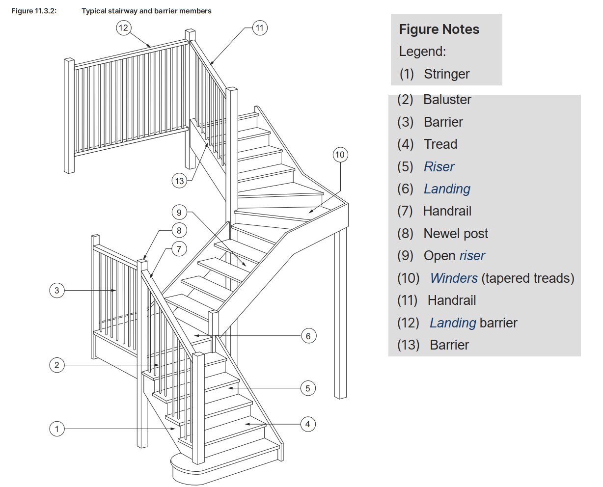
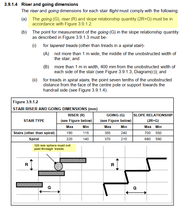
    3. BCA 3.9.1.4 – Riser and Going Dimensions:
    Further, BCA 3.9.1.4 provides specific dimensional requirements for stair risers and goings, as illustrated in Figure 3.9.1.2. This figure shows the maximum and minimum values for risers (R) and goings (G), as well as the slope relationship (2R + G). Engineers must adhere to these dimensions for both spiral and non-spiral staircases to ensure that the stairs are not only safe but also ergonomically comfortable for users.

    4. Critical Figures:

    Riser (R): Must be within the maximum and minimum values—115 mm to 190 mm for standard stairs and 140 mm to 220 mm for spiral stairs.

    Going (G): Must be within the maximum and minimum values—240 mm to 355 mm for standard stairs and 210 mm to 370 mm for spiral stairs.

    Slope Relationship (2R + G): Must fall between 550 mm and 700 mm for standard stairs and 590 mm to 680 mm for spiral stairs. These values ensure that stairs provide both safety and comfort.

    5. Ensuring Compliance:
    As part of the detailed engineering process, it’s your responsibility to ensure that all specifications, such as the 125 mm riser opening limit and the exact riser and going dimensions, are strictly followed in the drawings, materials, and construction processes. This involves validating these measurements on-site and ensuring they are reflected accurately in both the design and construction stages.

    In conclusion, the detailed engineering process must ensure compliance with AS 1428.1 and the BCA, particularly regarding the requirement that the riser opening must not exceed 125 mm, as outlined in BCA 3.9.1.3. Additionally, the riser and going dimensions must conform to the standards specified in BCA 3.9.1.4. By adhering to these standards, you will ensure that commercial stairs and balustrades are safe, accessible, and compliant with Australian building regulations.

  • Safety Standards in Building Design – Key Requirements for Barriers, Handrails, and Fall Prevention

    Safety Standards in Building Design – Key Requirements for Barriers, Handrails, and Fall Prevention

    If you would like me to assist with your project, please send an email to koshy@tek1.com.au with your project specifications. Kindly use ‘Raj’ as the subject header.

    1. Barriers to Prevent Falls (Section 11.3.3)

    • Purpose: Barriers are required on various elevated surfaces to prevent falls.
    • Where Required: Install barriers along stairways, ramps, balconies, and any surface where a fall of 1 meter or more is possible. (see Figure 11.3.3a).
    • Exceptions:
      • Retaining walls (unless they are part of an access path). (see Figure 11.3.3b).
      • Certain window openings covered by specific provisions. (see Figure 11.3.7 and 11.3.8).

    2. Barrier Construction Standards (Section 11.3.4)

    • Height Requirements:
      • Stairs/Ramps: Minimum 865 mm above the stair treads or ramp floor. (see Figure 11.3.4a).
      • Other Elevated Surfaces: Minimum 1 meter for landings, balconies, and similar elevated areas. (see Figure 11.3.4a).
    • Design for Child Safety:
      • Openings in barriers should not allow the passage of a 125 mm sphere, the opening is measured above the nosing line of the stair treads, minimizing the risk of children slipping through. (the opening is measured above the nosing line of the stair treads)
      • Avoid horizontal elements between 150 mm and 760 mm above the floor, as they can facilitate climbing​. (see Figure 11.3.4b).

    3. Handrail Requirements (Section 11.3.5)

    • Placement: Handrails should be installed on at least one side of stairways or ramps, providing continuous support along their full length.
    • Height: The top of the handrail must be at least 865 mm above the stair treads or ramp surface. (see Figure 11.3.4b).
    • Continuity: Handrails should be continuous without interruptions, with exceptions for elements like newel posts.
    • Exceptions to Handrail Requirements:
      • Handrails are not necessary for stairways or ramps with elevation changes of less than 1 meter, on landings, or for winders with a newel post for support​

    This guide emphasizes key elements in designing safe, compliant buildings that align with the Australian Building Codes Board (ABCB) standards for fall prevention, especially around barriers and handrails. These regulations aim to protect all building users, especially vulnerable groups such as children, from potential fall hazards.

  • Addressing Design Discrepancies in Fixing Timber Wall to Steel Structures: An RFI Necessity

    Addressing Design Discrepancies in Fixing Timber Wall to Steel Structures: An RFI Necessity

    Author: RAJ (Arokiaraj Arputharaj)

    Addressing Design Discrepancies in Fixing Timber Wall to Steel Structures: An RFI Necessity

    When it comes to construction projects, precision and adherence to design specifications are critical. However, sometimes, practical considerations highlight the need for adjustments to those specifications. One such scenario involves the fixing of a timber wall to steel SHS columns and beams, where the original design calls for M12 bolts spaced 300 mm on centers.

    The Issue with 300 mm Spacing

    While the design specifies M12 bolts at 300 mm centers, this spacing is notably narrow for this type of application. Typically, such close spacing is reserved for situations where exceptional load-bearing capacity or additional structural support is required. In this context, a spacing of 600 mm on centers would be more than sufficient to secure the timber wall effectively, without compromising structural integrity.

    The concern with the 300 mm spacing is not just overengineering but also the practical implications on the job site. Implementing such close spacing requires more materials, labor, and time, leading to increased costs and potential delays. Moreover, drilling excessive holes into steel SHS columns for fixing purposes could weaken the structural integrity of the columns, which is an outcome that must be avoided.

    Alternative Solution: Gun-Fixing the Studs

    Given that the primary objective is to secure the timber wall to the steel structure, an alternative approach could be considered. Gun-fixing the timber studs directly onto the steel columns, without the need for drilled holes, is a viable option. This method is not only faster but also maintains the strength of the steel columns by avoiding unnecessary perforations.

    Raising the Issue: The Importance of an RFI

    Before proceeding with the job, it is essential to address this issue through a Request for Information (RFI). An RFI will formally document the concern regarding the overly narrow bolt spacing and propose the alternative method of gun-fixing. By raising an RFI, the project team can seek clarification and approval from the design engineers or the client to adjust the specifications accordingly.

    This step ensures that all parties are aligned, and any modifications to the original design are officially approved, reducing the risk of rework or disputes later in the project. It also demonstrates due diligence and a commitment to delivering a project that is both cost-effective and structurally sound.

    Conclusion

    In summary, while the original design calls for M12 bolts at 300 mm on centers to fix the timber wall to steel SHS columns and beams, this spacing is unnecessarily narrow. A 600 mm spacing would be sufficient, and an alternative method of gun-fixing the studs to the columns should be considered. Before commencing work, this issue must be addressed via an RFI to ensure that all stakeholders are in agreement and that the project proceeds smoothly and efficiently.

  • Managing Sticker-shock

    Managing Sticker-shock

    Author: RAJ (Arokiaraj Arputharaj)

    • The initial project was quoted at: $x
    • Changes were required on the project necessitating variations – at double the cost of the original quote!

    When this happens, it is ESSENTIAL that you call the client before you put in your variation documentation.

    Why?

    • The client will suffer from “sticker shock” after he sees your price.
    • “Sticker shock” means that the client will be so surprised, and shocked, that he will fall off his chair.
    • The client will lose trust in you.
    • The client will try to negotiate everything down.

    What should I do instead?

    • Call the client and say that the changes are huge.
    • Do not send variation documentation before addressing the “sticker shock issue”.
    • We cannot and do not negotiate on prices.
    • Going forward clients can choose between: (i) a fixed price quote – where we take on-board the risks of an infinite amount of variations, or (ii) where we charge variations but come in at a lower price.
    • Our variations are FIXED in price.
    • They are not negotiable.

  • Simplifying Erection with Steel Columns at 14 Ridgeway AV Kew

    Simplifying Erection with Steel Columns at 14 Ridgeway AV Kew

    Author: RAJ (Arokiaraj Arputharaj)

    Introduction

    At TEK1, we recently took on an exciting project at 14 Ridgeway AV Kew. This project is a testament to our commitment to delivering innovative solutions in steel detailing. During the design phase, we identified a potential erection issue involving the use of timber columns to support steel beams. Our proactive approach led us to recommend a change that would streamline the construction process and enhance the overall efficiency of the project.

    Project Overview

    The 14 Ridgeway AV Kew project involves the construction of a structure where two steel beams are supported by timber columns. This design posed a significant challenge: coordinating the efforts of two different types of erectors—one for steel and another for timber. This not only complicates the erection process but also introduces potential delays and additional costs.

    Identifying the Issue

    As steel detailers, our primary goal is to ensure that every aspect of the project is executed smoothly. We quickly realized that having two different erectors on-site to handle the steel beams and timber columns would create unnecessary complications. The need for precise coordination between the steel and timber erectors could lead to scheduling conflicts, increased labor costs, and potential delays in the project timeline.

    Proposed Solution: Steel Columns

    To mitigate these issues, we suggested replacing the timber columns with steel columns. This change offers several advantages:

    1. Streamlined Erection Process: With steel columns, a single erector can handle both the beams and the columns, simplifying coordination and reducing the risk of delays.
    2. Enhanced Structural Integrity: Steel columns provide better support for the steel beams, ensuring a more robust and reliable structure.
    3. Cost-Effective: By minimizing the need for multiple erectors, we can reduce labor costs and improve overall project efficiency.
    4. Consistency in Material: Using steel for both the beams and columns ensures uniformity in the materials, which can lead to better performance and durability over time.

    Client Approval and Implementation

    We presented our recommendation to the client, highlighting the benefits of using steel columns instead of timber. The client appreciated our foresight and agreed to the change. This decision not only simplified the erection process but also contributed to a more streamlined and cost-effective construction phase.

    Conclusion

    At 14 Ridgeway AV Kew, our proactive approach and attention to detail allowed us to foresee potential issues and implement effective solutions. By suggesting the use of steel columns, we ensured a smoother erection process and enhanced the overall quality of the project. At TEK1, we are dedicated to delivering excellence in steel detailing and construction, always putting our clients’ best interests at the forefront of our projects.

    Stay tuned for more updates on our innovative solutions and project successes!

  • PLATFORM EXTENSION

    PLATFORM EXTENSION

    Author: RAJ (Arokiaraj Arputharaj)

  • ROOKWOOD CEMETERY

    ROOKWOOD CEMETERY

    Author: RAJ (Arokiaraj Arputharaj)

  • LYRIC THEATRE GRATING

    LYRIC THEATRE GRATING

    Author: RAJ (Arokiaraj Arputharaj)

  • NAUTIQUE APARTMENTS ALUMINIUM FRAME

    NAUTIQUE APARTMENTS ALUMINIUM FRAME

    Author: RAJ (Arokiaraj Arputharaj)