Author: Vignesh Ranaganathan

  • PREFABRICATED CONCRETE ELEMENTS

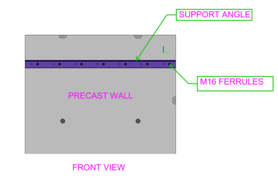
    (Temporary Fixing Inserts for As-Cast Element Tolerances)

    INTRODUCTION:

    To ensure proper alignment and structural efficiency in the handling and installation of prefabricated concrete elements by placing temporary fixing inserts within the allowable as-cast dimensional tolerances as specified in Australian Standard AS 3850.2:2015.

    Inserts for the temporary attaching of prefabricated concrete elements shall be placed within the nominal dimensional tolerances provided by the as-cast state, in order that there is proper alignment and structural efficiency for handling and installation.

     INSERT LOCATION TOLERANCES FROM A SPECIFIED POSITION

             TYPE OF INSERT     TOLERANCE, mm
                  Face lifting            
    Bracing           
    Strongback            
    Edge-lifting            
    Longitude            
    Thickness  
    ±20                   
    ±50                   
    ±5                   
    ±5                   
    ±20                   
    ±5

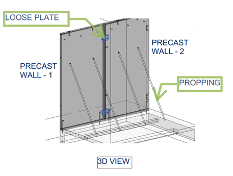
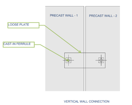
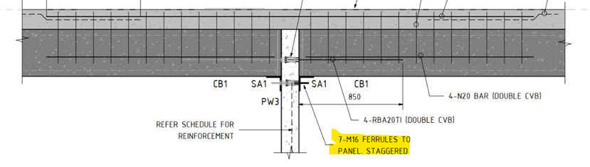
    The temporary elements are only used for demoulding, transport, erection.

    Once the panel shop drawing is issued for construction (IFC), the manufacturing process begins.

    However, the elements may not exactly match the shop drawing dimensions due to factors such as concrete pouring and vibration.

    These factors can lead to dimensional variations. In Australia, precast concrete manufacturing follows the standard AS 3850.2:2015, which provides insert location tolerances relative to the specified position.

     (For Example):

    This is the actual dimension of the Edge lifter

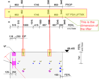
    This shop drawing is for IFC; after that, it will be used for the manufacturing process.

    (For Example):

    The edge lifter dimension after curing:

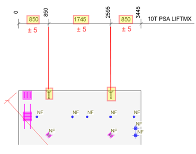
    After curing, the edge lifter dimension is acceptable with a tolerance of ±5 mm, as specified in the Australian Standard AS 3850.2:2015 (refer to Table 2.7)

  • PRECAST PANEL TO PANEL CONECTIONS USING TEMPORARY PLATE    

    INTRODUCTION :

    To explain the application and detailing requirements of temporary loose plate connections used in precast panel-to-panel joints. This document outlines the types of connections (parallel and corner), their structural purpose during erection, and their specific use in warehouse and multistorey buildings. It also highlights the importance of accurate detailing for cast-in ferrules and placement considerations to avoid clashes with structural elements like roof steel.

    The plate connection used in Precast Panel to Panel connection depends on weight, wind, loading, and shape. The plate also contributes to the additional strength of the panels.

    These connections are used after erection, as they are already structural connections at the panel bottom (grout tube with dowel bars), along with the brace connection. After that, an additional temporary plate is connected from panel to panel for extra strength.

    THE LOOSE PLATE TYPE OF CONNECTION:

    1. Panel to panel (Parallel).
    2. Perpendicular panel with corner connection.

    This type of connection is commonly used for panel-to-panel connections.

    1.PANEL TO PANEL (PARALLEL):

    2.PERPENDICULAR PANEL TO PANEL CONNECTIONS AT CORNER JOINT

    APPLICATIONS:

    WAREHOUSE BUILDING CONDITION.

    The panel-to-panel connection adds additional strength and also helps with propping.

    The loose plate connects to the panel surface with the help of cast-in ferrules.

    This type of connection is mostly used in warehouse projects, and the plate is usually not removed after erection.

    The detailer should provide exact locations with dimensions for cast-in ferrules. For example, refer to the drawing below.

    This type of connection is placed inside the building to avoid affecting the exterior appearance.

    MULTISTORE BUILDING.

    Basically, precast panel-to-panel connections involve steel loose plate connections to support the erection process. Mostly, this type of plate connection is temporary.

    Once the precast wall is erected, the loose plate is connected to the cast-in ferrules with the support of propping.

    Once panel erection is completed, the loose plate will be removed. The main reason for removing the plate is to achieve the panel finish.

    This type of connection is placed inside the building to avoid affecting the exterior appearance.

    NOTES:

        Generally, position all precast connections below the roof steel to avoid clashes with any roof steel works. When placed above the roof steel, they may interfere with the installation or alignment of roof components.

  • STAGGERED FERRULES PLACEMENT  ON PRECAST PANEL

    STAGGERED FERRULES PLACEMENT ON PRECAST PANEL

    The design drawings for one of our Precast Project we were working on suggests ferrules must be placed staggered as noted below.

    The Problem:

    However, these casting components, such as ferrules cannot be placed on both sides of a precast panel with a thickness of less than 250mm. This mainly causes ferrules to clash along its length. This approach will not work. Can you see why

    The Solution:

    One of the projects, for our client involves utilizing the staggered arrangement approach. Look at the (fg.1)

    (fg.1)

    The both sides of wall are provided with support angles SA1 to hold the slab/ Beam.

    Both sides are utilizing M16 ferrules, within the panel. The issue lies in the fact that the ferrule Height measures 96mm whereas the wall thickness is 150mm.

    Client using PSA Standard ferrules

    Example:

                       Wall thick – 150mm                                     

                       M16 Ferrule length – 96mm add both sides of wall  

                       96 + 96 = 192mm (greater than the wall thickness 150mm)

                       The length of the PSA P1696ZF is 96mm, as per the PSA schedule.

    Ferrules cannot be placed inline; the only option is to staggered them.

    Look at the (fg.2)

    (fg.2)

    The above ferrule placement factors and consideration is not required if the panel thickness is 250mm and above.