These details could be different for each job. Check the details provided by client. If missing ask. The detail Nos will be different. Use what is specific for the job
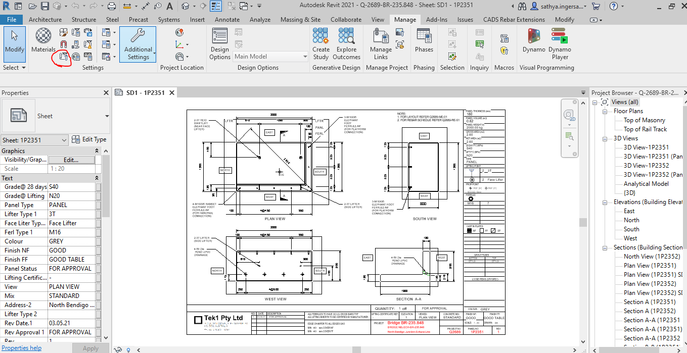
Project Details – Does the Revit file allow us to create Project Details. How and where is the data available to read?
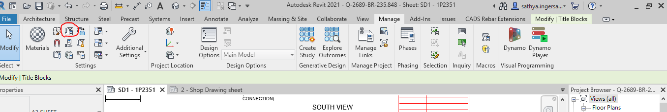
For Project information the details will be added and done in the Manage tab as shown below
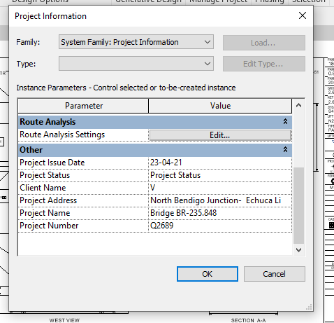
Step 1: Clicking to manage tab and click on the red clouded region as Project Information
Step 2: Entering the Data about the Project as Shown above
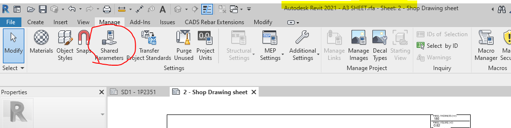
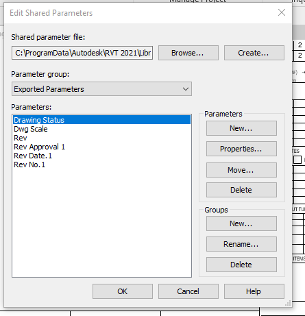
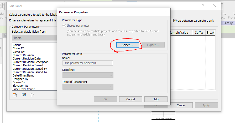
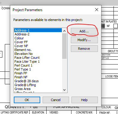
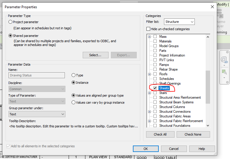
Step 3: Open the sheet family and click on the Shared Parameter Option in the Manage tab
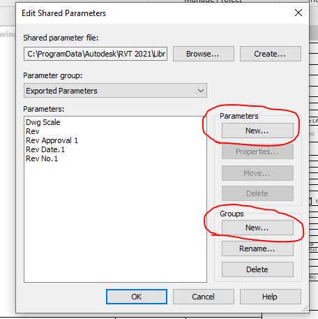
Step 4: Create the new parameter if needed and Create new group where the parameters are to be called for.
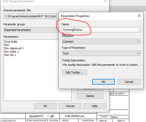
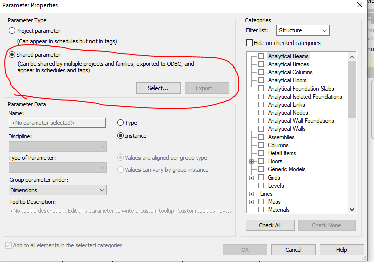
Step 5: Add the new parameter in the Paremter property. Once parameter done it can’t be edited and it has to be removed and create a new one .
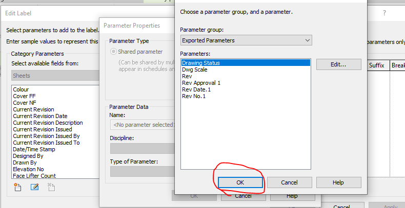
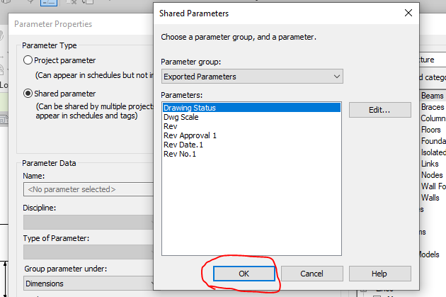
Step 6: Now the “Drawing Status” Parameter are now called under the Parameter group exported parameter.
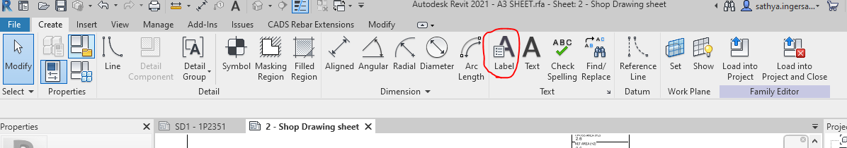
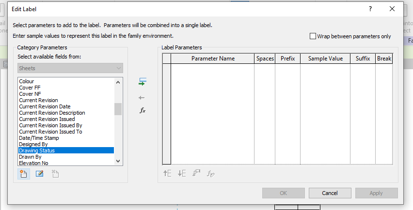
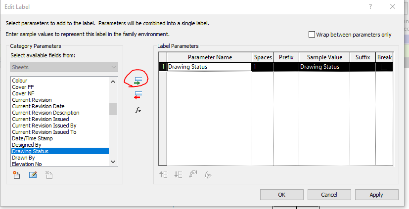
Step 7: Click the Label Parameter to call the label that are already created in parameter
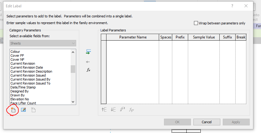
Step 8: The parameter which was created in shared was not displayed so click on the add parameter to call from the group.
Step 9: Click on the select button to call the shared parameter group defined.
Step 10: Click on the required parameter to call and click on ok
Step 11: The parameter which was not available in the list are now generated and called
Step 12: The parameter which was not available in the list are now generated and called to edit parameter list
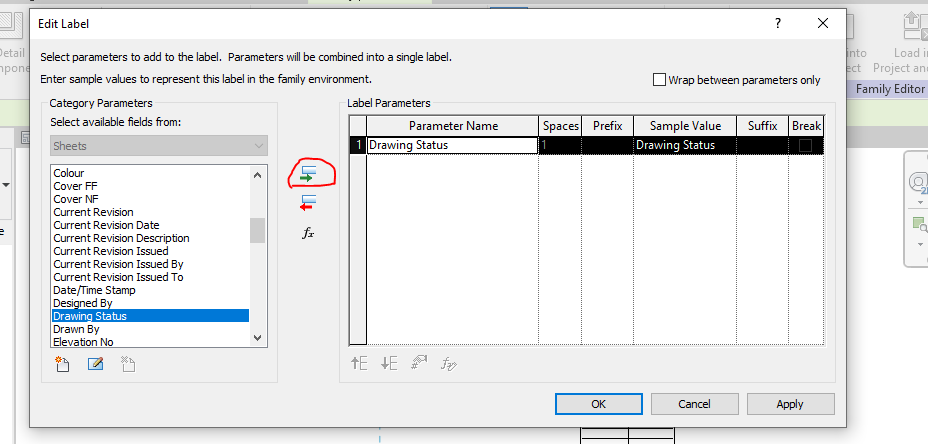
Step 13: Then click the add parameter lab clouded in red and the following parameter will be added in the label and then click ok.
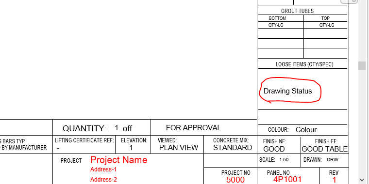
Step 14: The Label “Drawing Status” was now added in the Sheet Family
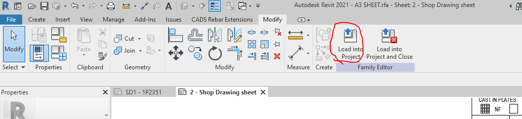
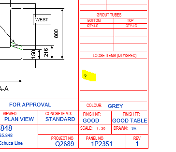
Step 15: Then click on the “Load into Project“ button to load the Shop Drawing Sheet in the Project.
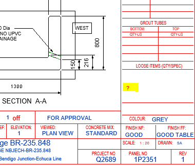
Step 16: The question mark we highlighted are the Parameter “Drawing Status” and it’s not editable at this stage because this shared parameter was not called in the Project Parameter. To sort this please follow the below steps.
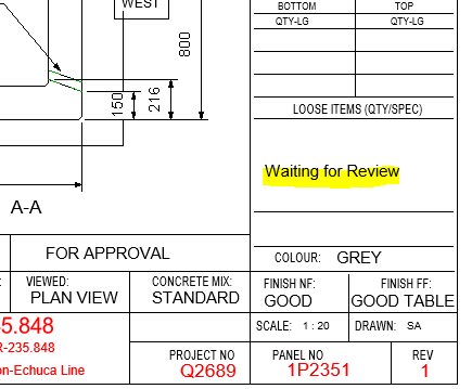
Step 17: Click on the project parameter to call the shared parameter we defined in Sheet family
Step 18: Click on to add button
Step 19: Click on to the shared Parameter and then click select button
Step 20: Click on the Parameter you defined previously and need to be editable and click ok.
Step 21: Once the shared parameter are defined on Project Parameter then click the Check box on the right end shown where the parameter to be display in your revit file and then click ok.
Step 22: Now you can see the question mark colour changes from red to blue which is editable one.
Step 23: The Parameters are added and edited in the Shop Drawing Title Sheet.
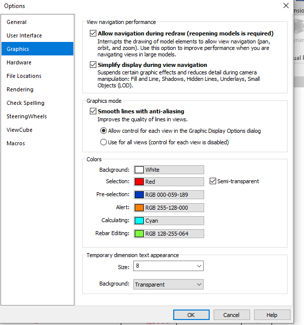
Idea: If you like to make your visuals to find the parameter is in editable or not editable please do the following thing below
Go to file tab and click on the option button below and set the graphics by changing the colours as shown below instead of same colour
Thanks to Koshy, Ben ,Venkat and Parthee for Supporting and guidance .
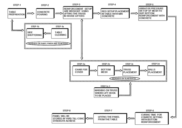
Extraction of individual Bubble deck Slab from Layout to Sheet
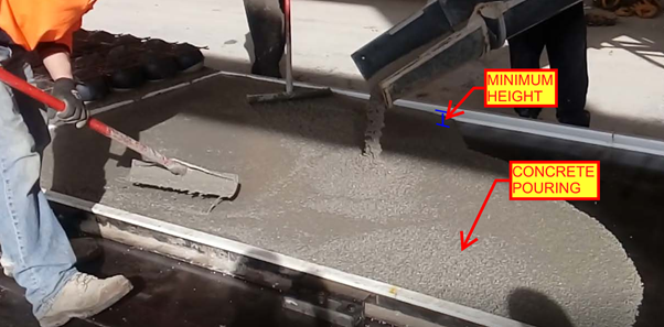
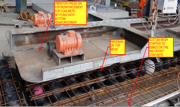
Calculation for Volume and weight for minimum slab pour in Factory
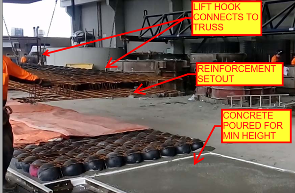
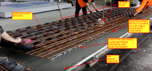
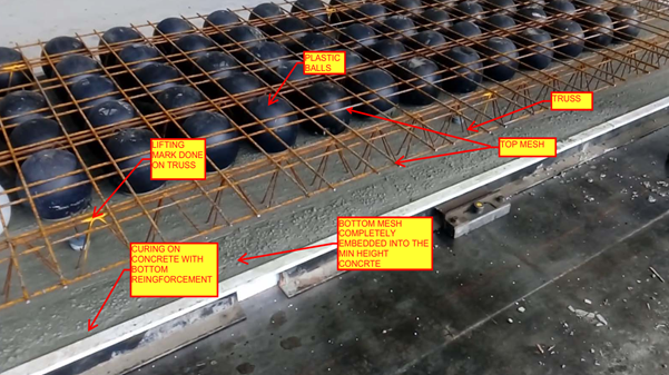
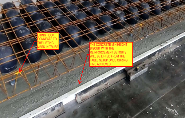
Placement of Lifters on the Min slab pour to lift the Min slab after pouring and curing form the factory
Reinforcement setout panel copied from the Source panel
Reinforcement Arrangements are done based on the Original Slab depth value given to the copied panel
Trimmer bars If the panel has Profile breaks and column Opening
Dimensioning of Panel ball set out for Panel Profile, Balls and cast in components present in the Min Slab Pour
Dimensioning of Reinforcement set out for Slab cover from the start of reo bar. Reinforcement setout Point selection and dimension for Truss arrangement.
Heading Notes for Panel ball set out with finish notes and Reinforcement setout
Notes for Block out and Penetration in Panel Ball setout
Notes for Trimmer Bar , Splice Bar and Loose U Bars in Reinforcement setout
List part for the cast in Components present inside the min concrete Slab
Thanks to Koshy, Ben and Venkat for Supporting and guidance .
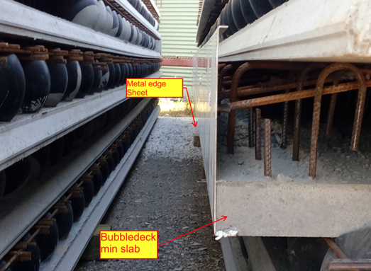
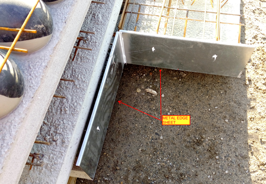
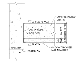
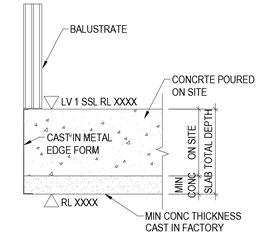
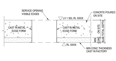
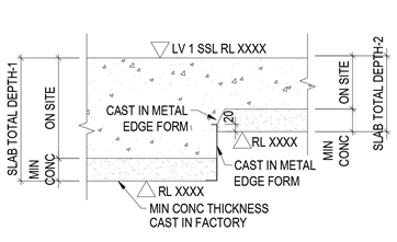
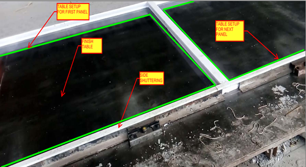
Metal edge is the 2mm to 3mm thick Galvanized Sheet which are mainly placed in the building edges of the Slab to stop the overflow of concrete while pouring on the Bubble deck Slab arrangements.
Metal edges are fixed in the factory and not on site; it will be fixed while pouring the minimum thickness concrete slab biscuit. So the metal edge are comes under the category of castin items in Bubbledeck Slab.
Application of Metal edges:
Bubbledeck Slab Edges that connects to Post fixed precast wall (Post fix wall will be erected once after the bubbledeck Slab are installed and Poured).
Slab edges which are free from the wall. Especially near to balustrade Areas
Duct and services void in slab which is present inside the Building
Soffiit Step / Slab fall in slab
Advantages :
Fine Finish of slab edge (Visible edges) can be obtained
No side shuttering is needed
Site work can be reduce due to fixing in factory long with min concrete Slab pouring
Disadvantages:
The cost of Metal edge sheet is high compare to timber because of galvanized
The metal edge to be order 10 days prior from casting on minimum concrete because of sheet galvanizing
Handling Problem:
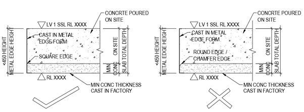
The Metal edge is not safe to use 450mm and above height. This may lead to bend and damage of metal edge sheet during the time of Bubbledeck Biscuit Transportation.
The Metal edge can’t be fixed on the round edge profiles of slab and applicable only for square edge Profile.
The slab that comprises of plastic void balls in middle which are sandwiched between top and bottom mesh to reduce the dead weight act on the slab
It is a biaxial hollow core slab where the concrete which is not performing any structural function are eliminated lead to reduction in 30% to 50% of its slab weight
Principle:
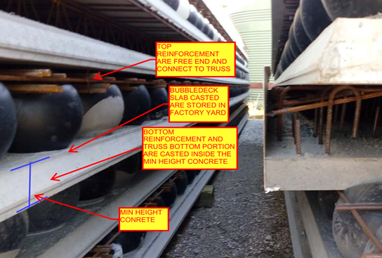
The Hollow plastic balls clamped with the top and bottom reinforcement are placed in the thin concrete of 60mm with max length and width of 10m x 3m to form a precast setup will be done in factory. After that the setup will be installed on site with connecting rods and by pouring concrete
The 35% saving in concrete composition was achieved by the ratio of Plastic ball diameter to the thickness of the slab depth
The reduction in slab weight leads to achieve the Load bearing capacity at a smaller slab thickness result in saving 40 to 50% of material consumption per Floor level.
Materials for Bubble deck slab:
Concrete
Standard with max aggregate size of 20mm
No plasticizers needed for concrete mix
Grade of concrete must be above M30
Reinforcement
Grade Fe-600 strength or high
Top mesh and Bottom Mesh reo of N12 bars max
Truss arrangements for vertical support of balls. Truss height depends on slab depth
Plastic Balls
Hollow sphere Plastic balls made of Polyethylene
Diameter of balls are depends on the Slab Depth. Ball sizes are 180mm, 225mm, 270mm, 315mm and 360mm.
Applications of Bubble deck Slab
Superior Architectural Design
Free choice of shape
Large corbels
Large spans and cantilever
No beam and fewer column results in flexibility
Interior design can be easily being altered.
Advantages:
Structural
Reduce the foundation size since 50% of the dead weight is already reduced by the slab.
Increased Strength due to biaxial Loading.
Longer spans are supported since no bean is required.
Column count can be reduced.
Excavation required less work.
Conduits and openings for service ducts can be easily incorporate in factory.
Construction
Less equipment is required due to light in weight.
Less work on Site construction.
Shuttering work and its Dismantling is not required since the 60mm concrete biscuit will act as shutter.
Construction hours and time taken is very less compare to conventional Slab
Engineering
High resistance against explosion due to biaxial flat slab system.
High Resistance to earthquake due to slab acts as elastic vertical structure.
User friendly to Post tensioning if running through slab.
Environment
CO2 emission due to concrete manufacturing quantity are reduced
Less material consumption
Less energy consumption
Less wood as no horizontal scaffolding
Economy
Sustainable for easy installation
Made to measure and saving material
Fast Implementation and construction
Reduction in Transportation Loading cost.
No shuttering and its cost needed
Disadvantage
Deflection will less higher than the Conventional Slab
Load carrying Capacity is lesser than the Conventional slab
Skilled labour required
Shear Load design consideration and its factor near the column area to slab care is required
The best way is via demonstration. Please see some of the video demos we have put together. It is not by accident that our drawings come to you quickly. There are 10 distinct stages. We will upload the rest of the stages as we get and when we get an opportunity.