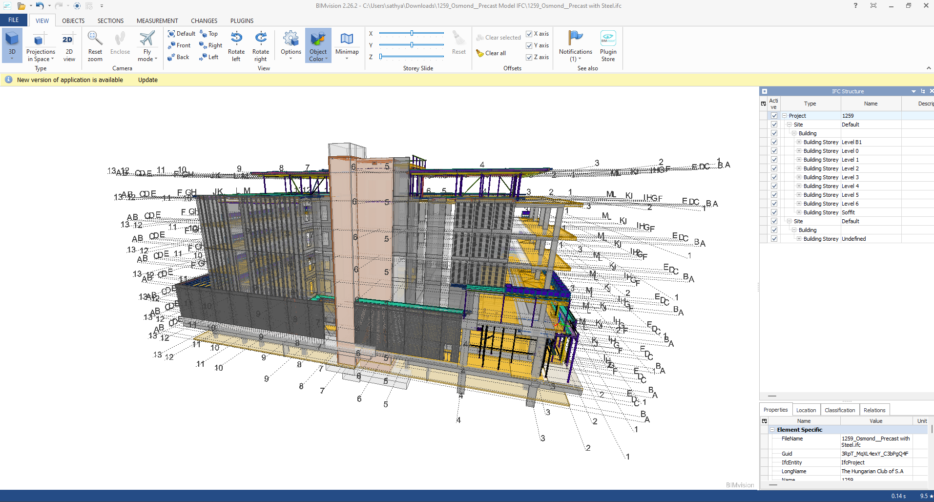
Category: Processes

  • TYPES OF MODEL VIEWERS FORMAT , PURPOSE AND ITS BENFITS

    A. IFC Mode

    Industry Foundation Classes (IFC) is an open file format developed by Building Smart Alliance. It is an international data exchange standard for exchanging building information across different software platforms. An IFC Model is just a model of a building or a construction project with all geometric, structural, and semantic information.

    Key Features of IFC Models:

    • Open Standard: IFC is vendor-independent, i.e., any software that supports it can be accessed, without regard for the vendor.
    • Static Data Exchange: It is mostly utilized for data exchange between software tools, data import, and export. For instance, an architect can create a model using Revit and export it as an IFC file, which can then be imported into structural engineering software like Tekla or SAP2000.
    • Limitation of Real-Time Coordination: IFC files are representations of the model at a specific moment. Changes in one application are not duplicated in another except where the file is re-exported and re-imported.
    • Use Cases:
    • Exchange of models between stakeholders with various software.
    • Ensuring interoperability in interdisciplinary projects (e.g., construction, engineering, and architecture).

    Advantages of IFC Models:

    • Encourages collaboration and interoperability in BIM workflows.
    • Reduces errors by making sure all stakeholders are working from the same information.
    • Allows clash detection and coordination between different disciplines.

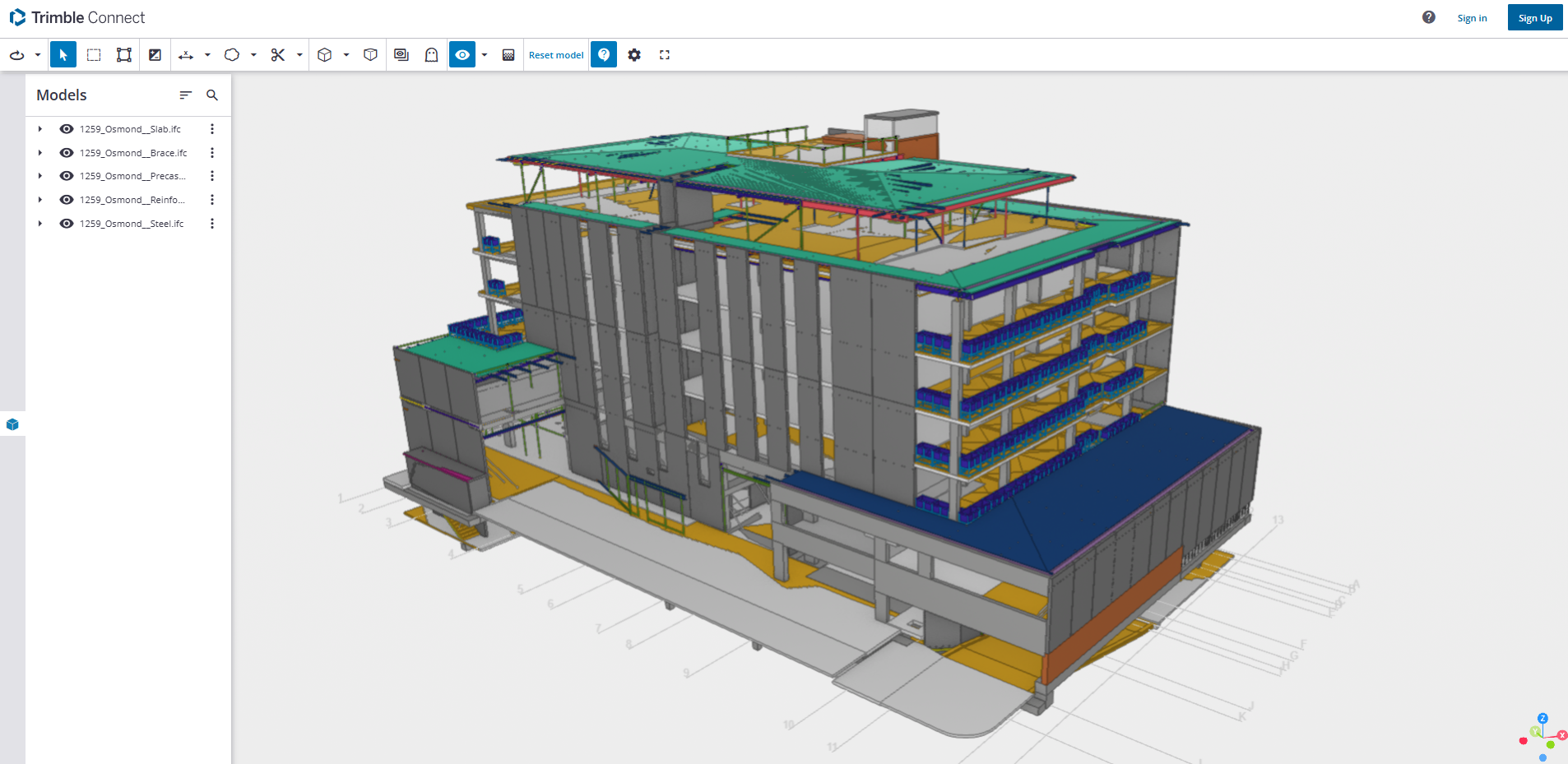
    B.  Live Link Model Viewer

                      A Live Link Model Viewer is software that enables real-time sharing and visualization of BIM models on various software platforms. Unlike IFC models, which are pre-exported static files, a Live Link Model Viewer enables multiple users to work on the same model at the same time using different software programs. Common examples of Live Link Model Viewers are:

    Revit Live: A cloud-based collaboration platform by Autodesk.

    Trimble Connect: A BIM data management and sharing tool.

    Key Features of Live Link Model Viewers:

    1. Real-Time Collaboration: One software application’s changes are reflected immediately in the model viewer and other linked applications.
    • Dynamic Data Sharing: Unlike static IFC files, Live Link Model Viewers offer dynamic, real-time linking between software applications.
    • Multi-User Collaboration: Multiple stakeholders can view and edit one model at the same time even though they are in different software.
    • Use Cases:
    • Real-time collaboration among architects, engineers, and contractors.
    • Collaborative design review and clash detection.
    • Smooth communication between teams working on different software platforms.

    Advantages of Live Link Model Viewer Benefits:

    • Make collaboration more effective and faster.
    • Eliminate the need for repeated file imports and exports.
    • Enhance accuracy by getting the entire team to work on the current version of the model.

  • Changes in Consultant drawings between Quotation stage to the Project stage? You must check: here’s why…

           It is essential to cross-check the revised consultant drawings we receive against the original drawings from the Quotation stage before commencing the project because this may affect prices.

    For example, the panel break up, or the panel specs might have changed. If they have changed, this might have a material impact on price such as concrete and reinforcement cost.

    What should we do when they make changes?

    1. Check the consultant drawing revisions and their date (between the quotation and the current stage).

    For example:

    2. Highlight the changes that occurred and mark them down in the latest structural PDF.

    For Example:

    3. Prepare a summary document report outlining the modifications.

    For Example:

    4. Inform the precast manufacturer and builder about these changes by sending the relevant information via email.

    For Example:

    Why do we need to check the consultant drawings?

         This verification process will enable the precast manufacturer and builder to re-evaluate the timeline based on the information that was previously quoted. This allows potential Cost issues that could cause confusion or delays in the project timeline to be identified and resolved early on such as

    • Cost estimation of individual precast panels, including their respective panel areas and concrete volumes, for manufacture.
    • Cost estimation of approximate reinforcement and mesh weight requirements.
    • List of cast-in items and loose items required, approximate quantities.

    What are the key factors that need to be verified in the consultant drawings from a precast perspective?

    1. Panel Thickness and Types: Verify the panel thickness and types used, as specified in the Structural Drawings.

    2. Panel Count: Confirm the panel count based on the panel split, as detailed in the Structural Drawings.

    3. Panel Transportability and Tonnage: Conduct a transportability check and verify the tonnage of the panels from our end.

    4. Panel Reinforcement:

    • Perimeter bar diameter
    • Mesh type used and its placement
    • Additional reinforcement provided in the panel typical detail
    • Reinforcement on central or either side ( specify location)
      (Refer to Structural Drawings for details)

    5. Precast Wall Pattern and Special Moulds: Verify the precast wall pattern and special moulds required, as specified in the Architectural Drawings.

    6. Panel Finish: Confirm the panel finish, as specified in the Architectural Drawings.

    7. Panel Connection Details: Verify the panel connection details, if applicable, as specified in the Structural Drawings

  • Help Fabricators Claim Their Costs

    When something changes, this is what Fabricators want:

    1. They want the updated Steel Reports:
      1. Steel has a cost.
      2. Labour has a cost.
      3. Welding has a cost.
      4. Cranage has a cost.

    They also want:

    2. An updated IFC model, with a short summary:

    3. How much more steel is required:

    • 3 tonnes more steel. See the attached IFC model (or at least a link to it).

  • Tek1 – Tekla Tools

    Dimension Bolts

    Set up Instructions

    • Source code (sorry folks it’s a private repository).
    • Download program here.
    • Only works for: Tekla version: 19.1i
    • Run Installer.
    • SmartScreen may warn you about this program – by pass SmartScreen.

    Instructions:

    • Only dimensions horizontally and vertically. This means if you use some crazy views / angles it won’t work – and it will give the wrong dimensions.
    • You must select a window from within the view, or else it will crash.

    Trouble shooting: it doesn’t work!

    • Please check that “Toggle crossing selection” is on.
    • Allow “Select points”.

  • Memo 14 – Private details (e.g. links) should be in the private section only

    Philosophy: make things AS EASY as possible for your clients, do not confuse them.

    If someone sends you a link, that you cannot access how would you respond?

    The solution? Add private links and other details in “private details” section.

    There will be no confusion for the client.

  • TEMPORARY CONNECTION WITH DETAILS

    Precast erection procedure having the set of sequences. When the panel is installed on the slab, props are fixed to stable the panel, then panel was unhooked from crane then the temporary stich plate or stich angles are connected to the next panel through cast in ferrule, which is casted on the precast panel.

    The temporary connection is additional support for the precast panel for until grouting the grout tube & slab were connected to the particular panel. The panels are easily leveled up with respect to the connected panel. Minimize the no of brace connections. Easy to maintain the panel gap.

    Based on the position of panels & face of the connection it is classified as below,

    1. In-line stich plate connection.
    2. Internal Stich angle connection.
    3. External stich angle connection.
    4. On edge stich angle connection.

    1. In-line stich plate:

    When the panel are next to each other the temporary connections are made by the straight stich plate with ferrule as mentioned below picture.

    2.Internal Stich angle:

    When the panel is perpendicular each other and inside corner is access to perform the connection, the internal angle stich angle is being used.

    3. External stich angle:

    When the panel is perpendicular each other and outside corner alone is access to perform the connection, the external angle stich angle is being used.

    4.On edge stich angle connection.

    Some cases, same level panels one is erected on top of slab and another one is located on ceiling level is supported by on-edge ferrule mentioned as below picture.

  • CAST-IN PLATE WITH DETAILS

    A steel plate which is casted in to concrete for connection purpose is named cast-in-plate. Connections may be required to carry shear and axial force between the precast elements for applied load conditions.

    Cast-in plates are used to tie/ fix,

    1. Concrete or precast panels to each other.
    2. Precast to insitu slab.
    3. Steel beams to the Precast panels/slabs.

    All purpose of connection except steel beam to precast connections required pair of cast in plate connected by a welded plate . But the steel beam to precast connection required only a cast-in plate with cleat plate is enough . All the plates and connections details are need to approved by Structural Engineer.

    1 Panel to Panel connection:

    Normally the lift shaft panels & stair panels have to connect withstand maximum shear and axial loads. The vertical panel joints are made by the cast-in plate connection. Minimum two no of connections per level is needed (need to get structural engineer advise).

    The cast in plate casted with pocket to cover on later stage. Both perpendicular & in line panels are also can be able to connect. We can able to connect insitu wall to precast panel also by this method. Refer blow picture for better understanding.

    2. Precast to Insitu slab Connection:

    For Particular requirement the precast should be connected with slab. One cast in plate casted in to the slab and another one is casted in to the precast and both the plates are connected through weld plate by weld on site. Refer below picture for better understanding.

    3. Steel beams to the Precast Connection:

    Now a days the construction system are versatile various types of constructions systems are used to complete the same building. Steel building with precast walls are also preferred as a one type of construction system.

    Where the steel beams are meet the precast panels the cast-in plate is used to connect it. Here instead of weld plate cleat plate is used to connect between the steel member to precast wall. The cast in plate on the precast walls not cast with the pocket it is flush with surface.

  • WATERPROOFING AND ITS ADVANTAGES

    • Waterproofing:
      Normally exterior precast walls are constructed with joints and window openings. It can be easily affecting the moisture infiltration. Waterproof materials are applied in these areas to eliminate the moisture intrusion to the precast panel.

      we are defined edges are used to avoid this, it made upon wood or Foam (Thermocol).
      Top of Step Joint.
      Bottom of Step joint.

      If we require any special type of edges, it’s formed related to the above edges.
      Below images are given to reference the edges.

    • Advantages:
      1. Increase the lifespan of the structural Elements.
      2. Prevents the rusting of reinforcement in wall.
      3. Reduced the maintenance cost of the building.
      4. Prevents wetness inside of the building.
      5. Prevents leakages from the walls and ceiling.
      6. Prevents the formation of cracks on the surface of the building.
      7. Water absorption will be reduced.