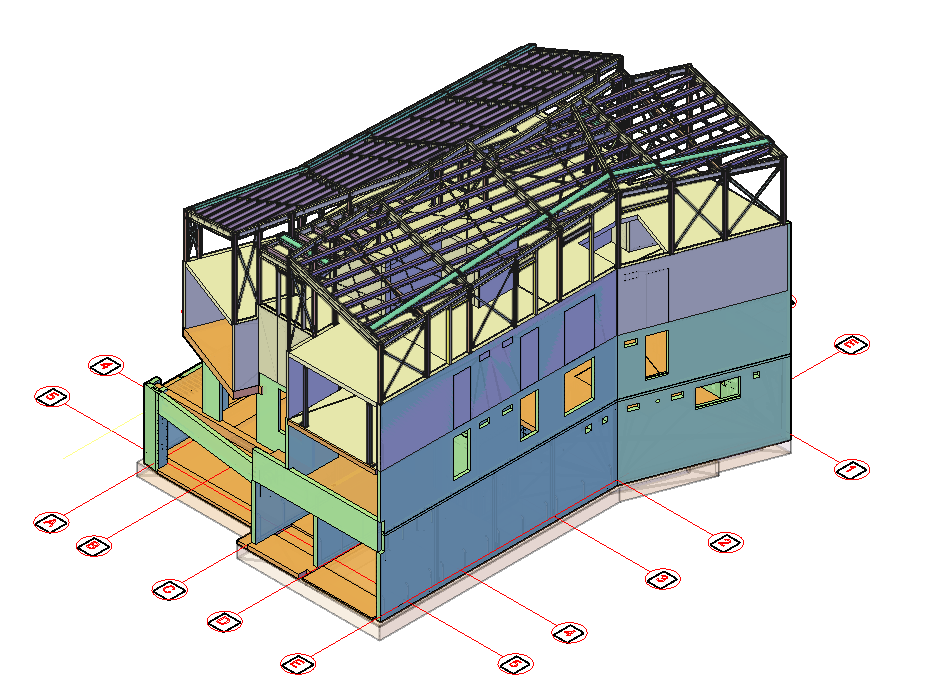
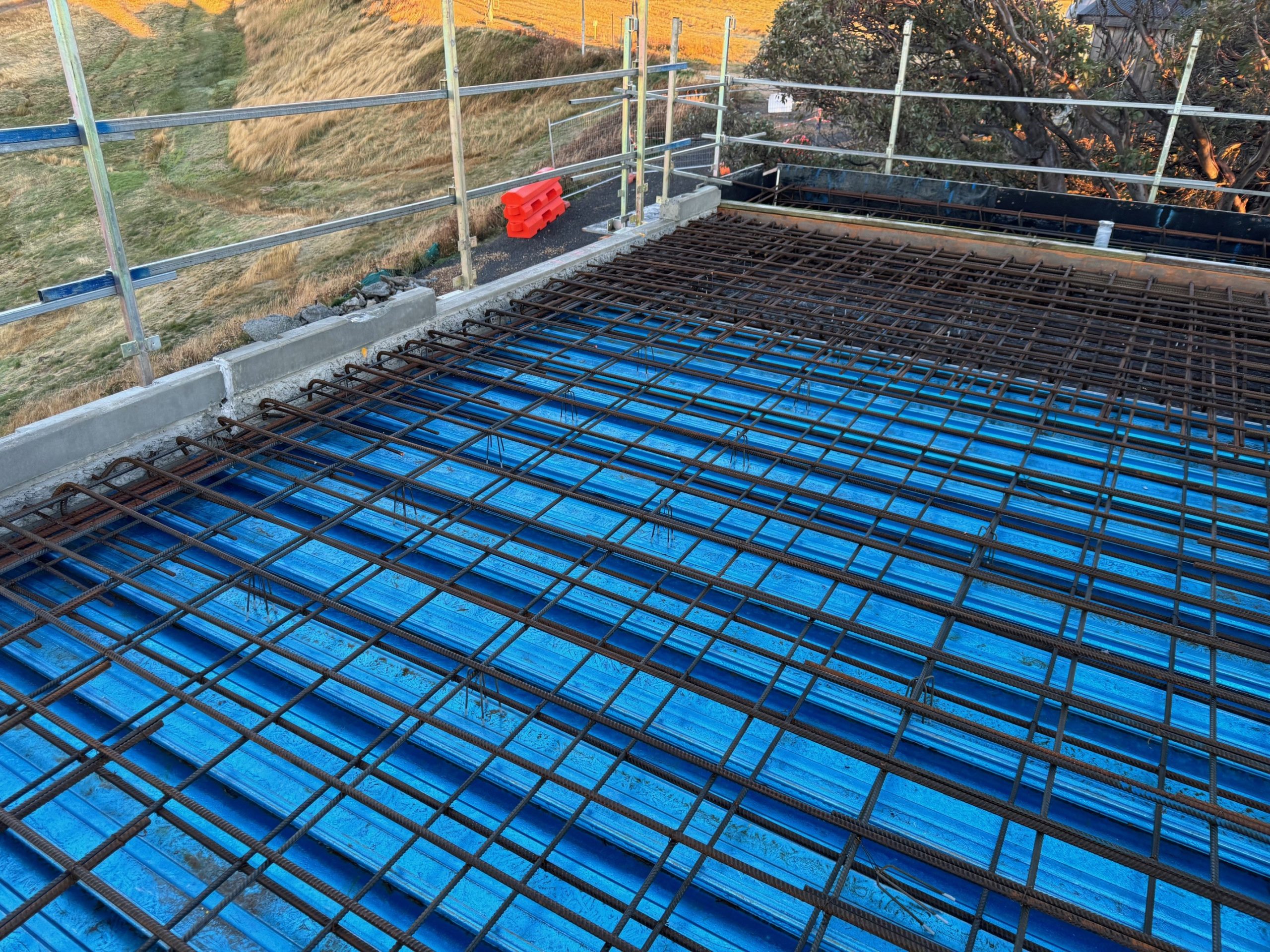
We are proud to showcase our contribution to Chalet 1 – White Horse Village, a unique and technically demanding project located in a mountainous region. This development presented several engineering and detailing challenges, and our team was honoured to be part of the solution — delivering precision, coordination, and innovation from start to finish.
Technical Challenges
This project stood out due to its unique geometry and remote location. The major challenges included:
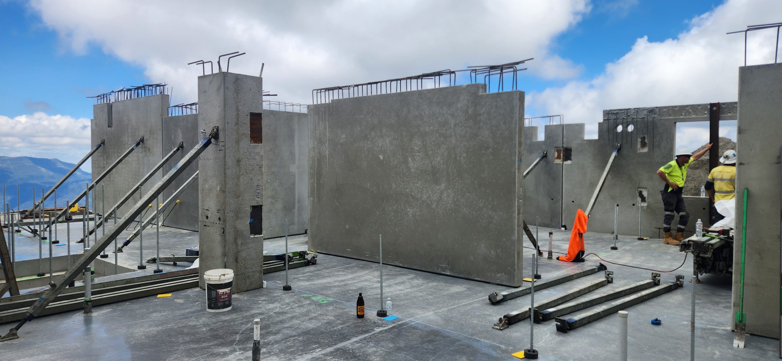
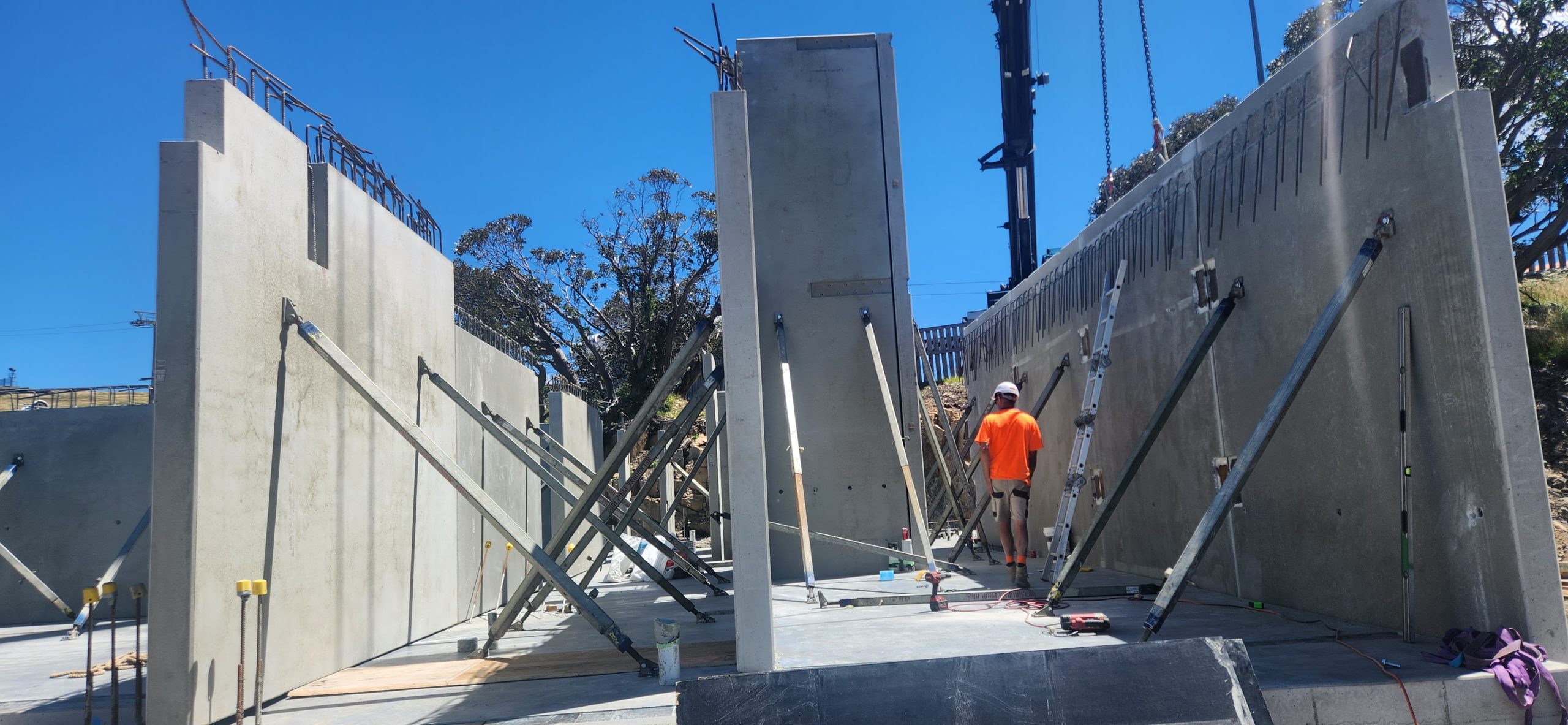
Angled Upstand Panels: Required precise detailing to ensure proper alignment and installation
Angled CIP Connections: Demanded detailed planning and coordination for constructability
Hybrid Slab Systems: Seamless integration of different slab types needed high-level coordination between trades
Mountainous Terrain: Site conditions added complexity in anchorage planning, tolerance adjustments, and logistics
Tools & Collaboration
Software Used: Revit & AutoCAD
Team Collaboration: Close coordination with structural engineers, architects, and production teams ensured accuracy, clarity, and timely delivery of shop drawings
(Temporary Fixing Inserts for As-Cast Element Tolerances)
INTRODUCTION:
To ensure proper alignment and structural efficiency in the handling and installation of prefabricated concrete elements by placing temporary fixing inserts within the allowable as-cast dimensional tolerances as specified in Australian Standard AS 3850.2:2015.
Inserts for the temporary attaching of prefabricated concrete elements shall be placed within the nominal dimensional tolerances provided by the as-cast state, in order that there is proper alignment and structural efficiency for handling and installation.
INSERT LOCATION TOLERANCES FROM A SPECIFIED POSITION
TYPE OF INSERT
TOLERANCE, mm
Face lifting Bracing Strongback Edge-lifting Longitude Thickness
±20 ±50 ±5 ±5 ±20 ±5
The temporary elements are only used for demoulding, transport, erection.
Once the panel shop drawing is issued for construction (IFC), the manufacturing process begins.
However, the elements may not exactly match the shop drawing dimensions due to factors such as concrete pouring and vibration.
These factors can lead to dimensional variations. In Australia, precast concrete manufacturing follows the standard AS 3850.2:2015, which provides insert location tolerances relative to the specified position.
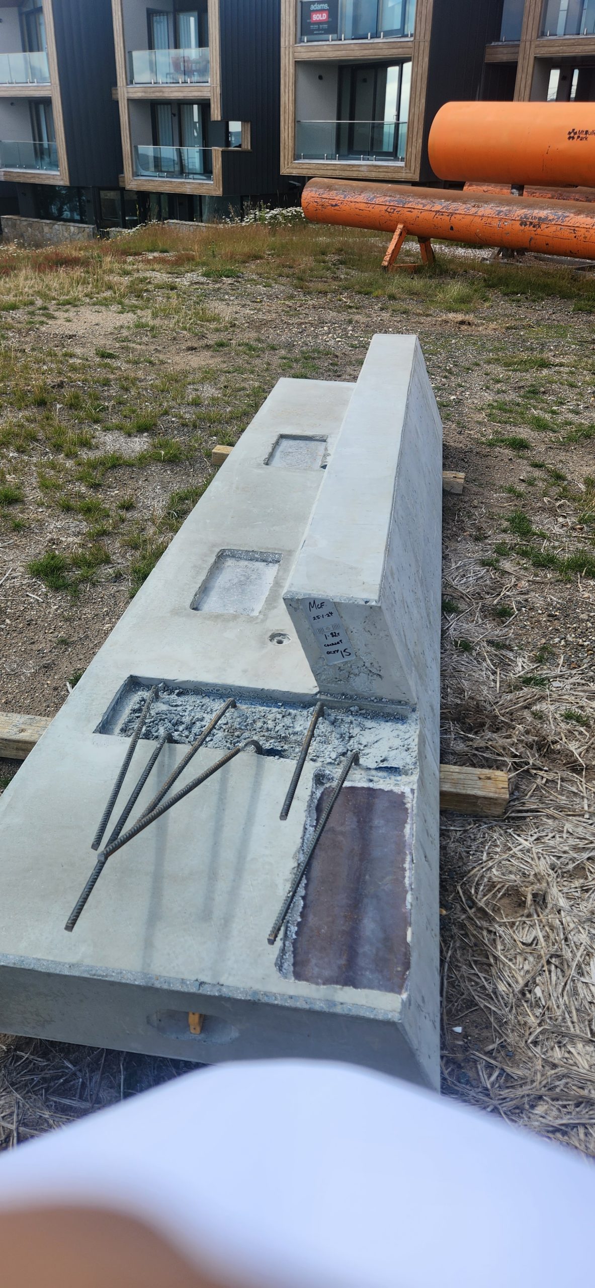
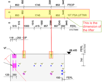
(For Example):
This is the actual dimension of the Edge lifter
This shop drawing is for IFC; after that, it will be used for the manufacturing process.
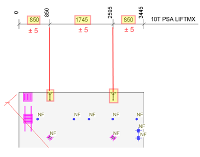
(For Example):
The edge lifter dimension after curing:
After curing, the edge lifter dimension is acceptable with a tolerance of ±5 mm, as specified in the Australian Standard AS 3850.2:2015 (refer to Table 2.7)
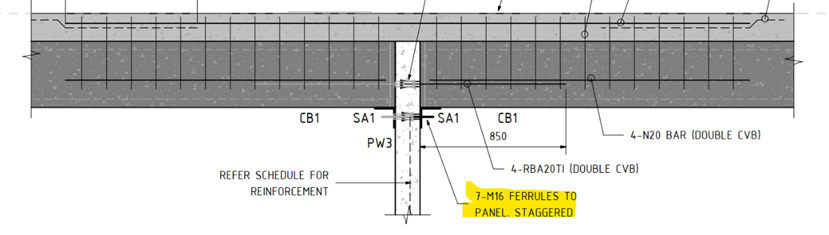
The design drawings for one of our Precast Project we were working on suggests ferrules must be placed staggered as noted below.
The Problem:
However, these casting components, such as ferrules cannot be placed on both sides of a precast panel with a thickness of less than 250mm. This mainly causes ferrules to clash along its length. This approach will not work. Can you see why
The Solution:
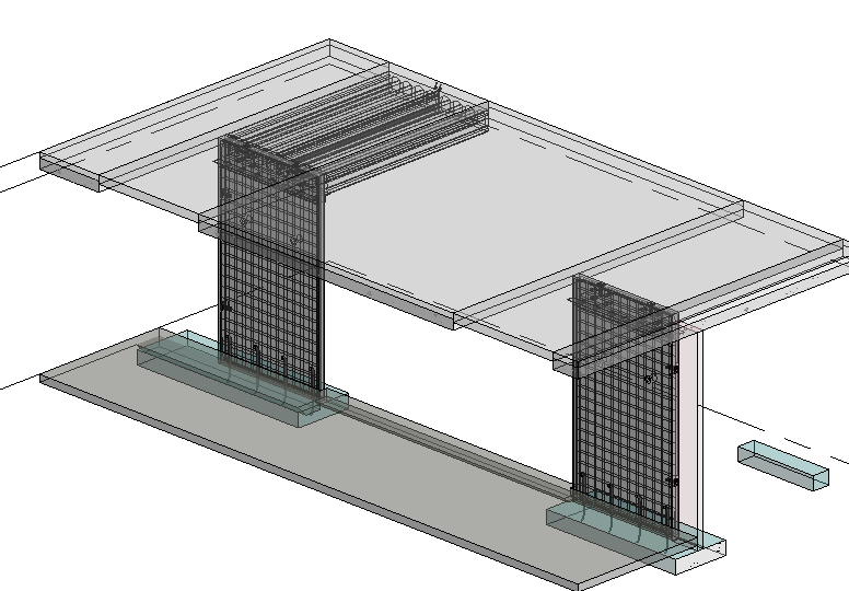
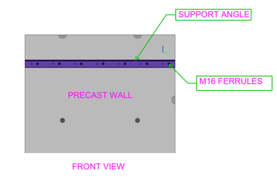
One of the projects, for our client involves utilizing the staggered arrangement approach. Look at the (fg.1)
(fg.1)
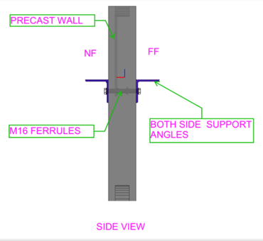
The both sides of wall are provided with support angles SA1 to hold the slab/ Beam.
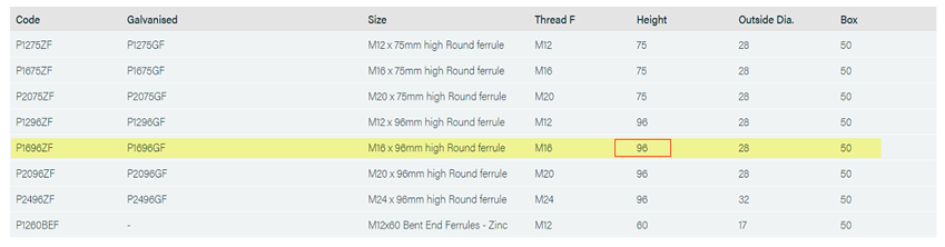
Both sides are utilizing M16 ferrules, within the panel. The issue lies in the fact that the ferrule Height measures 96mm whereas the wall thickness is 150mm.
Client using PSA Standard ferrules
Example:
Wall thick – 150mm
M16 Ferrule length – 96mm add both sides of wall
96 + 96 = 192mm (greater than the wall thickness 150mm)
The length of the PSA P1696ZF is 96mm, as per the PSA schedule.
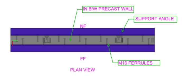
Ferrules cannot be placed inline; the only option is to staggered them.
Look at the (fg.2)
(fg.2)
The above ferrule placement factors and consideration is not required if the panel thickness is 250mm and above.