We can easily select objects as an input – objects which was can iterate over and apply a series of operations or checks out. But how do we return a selection of objects back to the user?
Background: What are we trying to do?
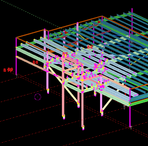
We have programmatically identified some model objects that we want to select in the model – to attract attention to the user and to allow her to easily identify all such objects. In this particular case we will be creating some beams. And then, we will select those beams in the model. Here is a code snippet to get you started:
How are you going to ensure that the starter bars do not clash? You’ve got 1000s of panels to detail and a dozen detailers working on different projects. How are you going to manage this?
What is the problem?
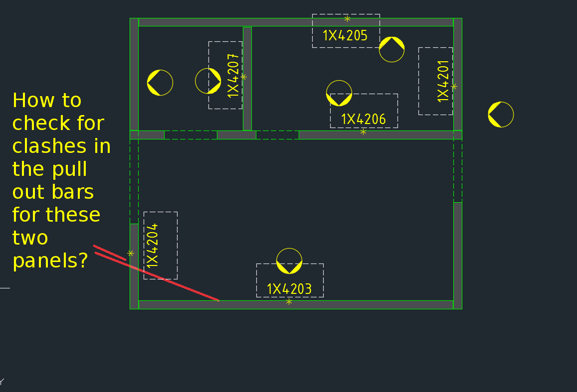
Consider this situation – you’re got a marking plan in front of you. You want to make sure that the ferrules in corner panels do not clash. How are you going to do that?
How would you solve the problem?
You’d have to find the corner panels, and then go to the appropriate drawing – both of them mind you – and you’d have to make sure that they are at different heights. That can get very tedious and it’s very time consuming, and more than likely, you’ll make some mistakes – because the panel elevations might not be adjacent to each other.
It’s not the easiest thing to see and compare in AutoCAD.
What is a better way to solve the problem?
But now you have a tool which allows you to easily compare the heights of the ferrules in two panels, straight from the marking plan.
There’s a lot of code and logic which goes with this. Perhaps I will outline it in another blog post.
Code Synopsis
For a very, very brief description of the overall route used, you can check out the code synopsis from my sister blog here. There I post the base class and interfaces used to derive the result – but have excluded all the implementation details.
Video Demonstration
Here is the video demonstration – and yet another example of the type of technologies and innovations you will have at your disposal if you work with us:
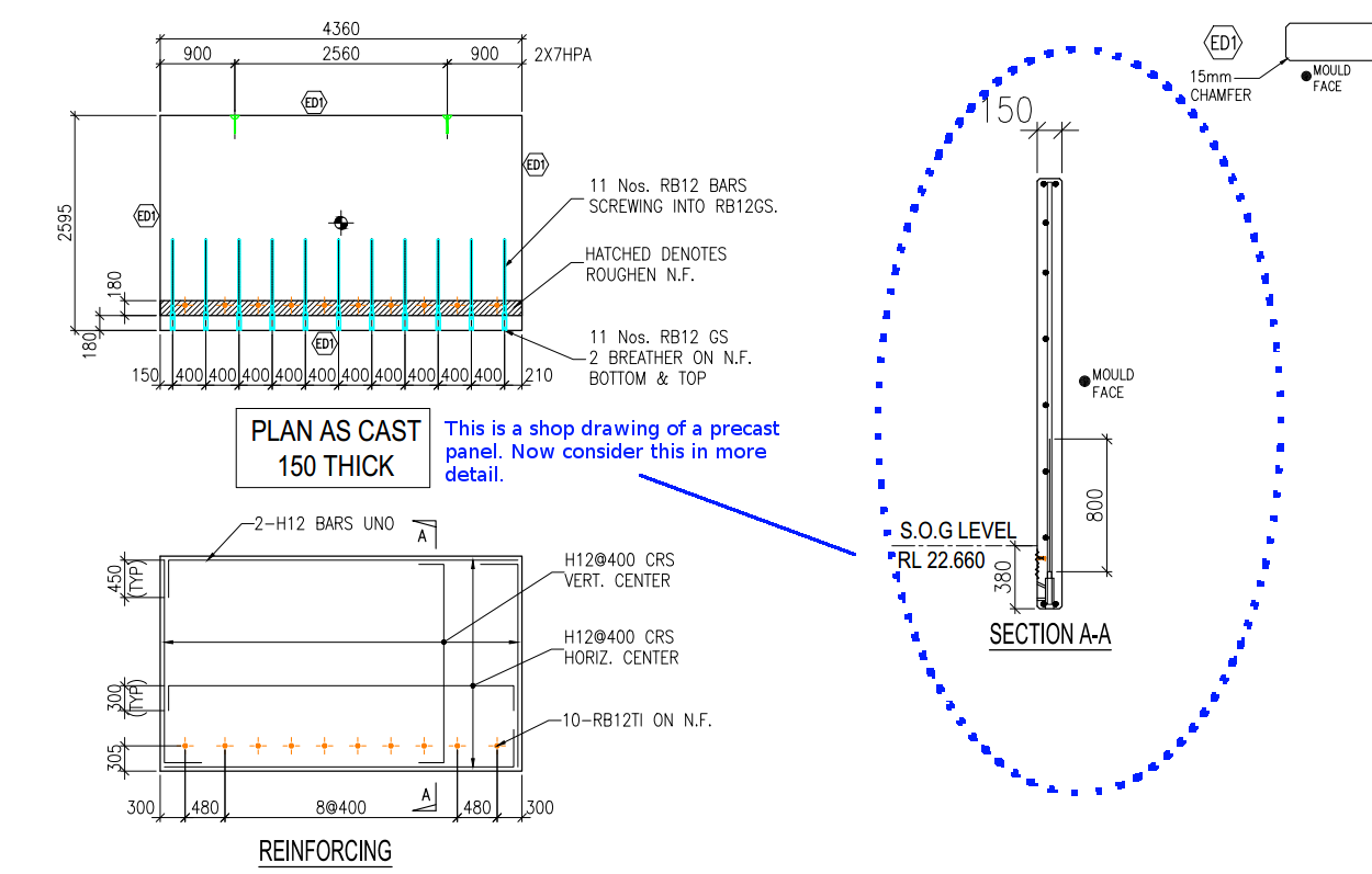
Cover refers to the distance between the outside of a concrete structure and the reinforcement. Perhaps see this from the diagram below:
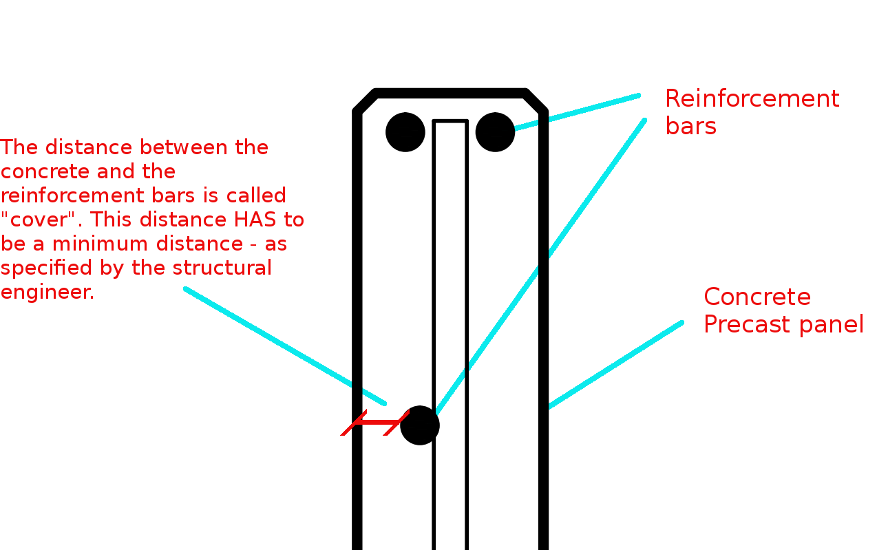
This is a general overview. Now let us zoom in and see more detail.
The distance between the concrete and the reinforcement bars is called “cover”. This distance has to be a minimum distance – as specified by the structural engineer.
You need to have a minimum cover:
There needs to be a minimal distance between the reinforcement bar and the outside of the panel.
Why do you need this?
Reduces Corrosion
Having a decent amount of cover reduces the rate of the corrosion of those reinforcement bars. If you have only 5 mm of cover – if the bar is literally just below the surface of the concrete, then that reinforcement is going to corrode away very quickly – especially if you are close to the sea. This means that the concrete will lose its strength very quickly, and a catastrophic failure might be on the cards. That’s why it is very important that the concrete does indeed have some minimal cover.
To Improve the Structural Integrity of the Concrete:
If you have the reinforcement bar too close to the concrete, then the structural integrity of the structure will be somewhat compromised.
Fire Protection:
If at all there is a fire, you don’t want the reinforcement bars igniting. If it does then the fire is sure to blaze out of control. That’s another reason why it’s very important that the bars some minimal distance away from the surface of the concrete. That will better enable the structure to remain in tact if at all there is a fire.
A Response to a Reader’s Question:
A diagram attached with a question from a reader.
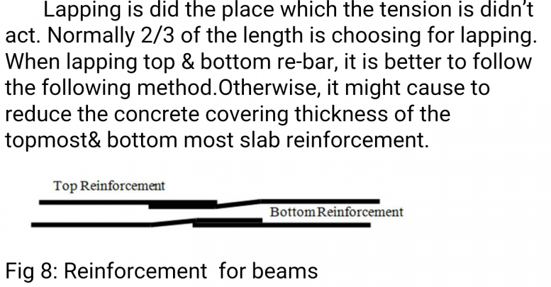
“(Q1) It appears that one of the lapped bar is bent while the other isn’t. Or is it just a drawing convention problem?”
(Q2) I don’t get why the lapped bars have to be positioned differently when placed on the top vs at the bottom in order to ensure that the concrete thickness will not reduce, as stated in the figure. My thought is that both positioning ways occupy the same volume.
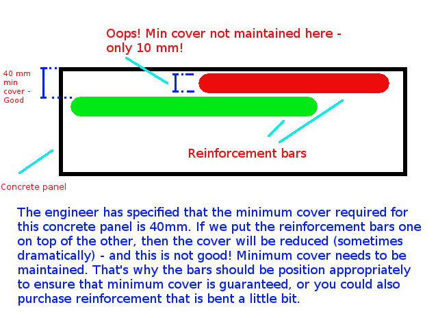
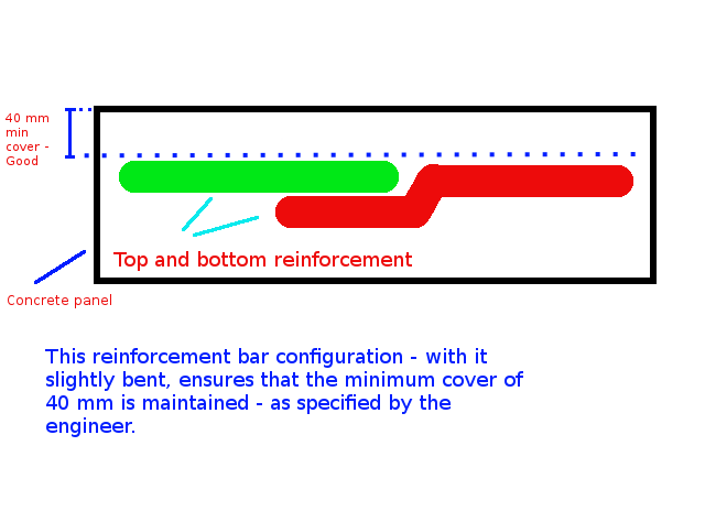
The answer to this question is best understood by studying the below diagrams:
Caption: The engineer has specified that the minimum cover required for this concrete panel is 40mm. If we put the reinforcement bars one on top of the other, then the cover will be reduced (sometimes dramatically) – and this is not good! Minimum cover needs to be maintained. That’s why the bars should be position appropriately to ensure that minimum cover is guaranteed, or you could also purchase reinforcement that is bent a little bit.Caption: This reinforcement configuration – with the reo slightly bent, ensures that the minimum cover (in this case 40mm) is maintained – as specified by the engineer.
The Answers to the Questions
(A1) When I draw reinforcement, I do not add a lot of the essential details which are assumed to be standard workshop practice. We are required to maintain a minimum cover. The diagram you have posted above is an example of what actually occurs in practice (but is almost never drawn that way). The reason it is bent is to ensure that the minimum cover requirements are not compromised.
(A2) That is absolutely correct – the panel’s thickness will not be reduced, but the thickness of the cover will change, depending on how one places the “reo” (reinforcement) rods.
If you’ve run AcCoreConsole and can’t bring back the normal user interface, just remember this trick.
So I’ve just managed to run AcCoreConsole – some script. And it’s changed some settings. And now when I open regular AutoCAD, when I type in netload – it seems that I’ve lost the ability to open/select things using the user interface. Now I have to manually type out long file names into the command line which is the height of tedium.
Why did it happen?
It happened because we were not meticulous in the running of our AcCoreConsole scripts. We should be sure to ensure that we save settings properly so that when users use the regular AutoCAD program, they don’t have to reconfigure the entire environment away from what works well for AcCoreConsole, back to what they are normally used to.
How to fix the problem immediately
You can file the problem by typing in:
That should change those settings back to normal.
How to avoid the problem in your script file
Don’t forget to return it to the original settings: anything beginning in a semi-colon is a comment and will not be executed.
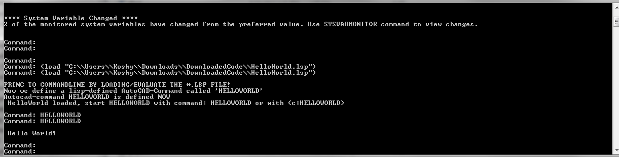
A commenter had some trouble loading the files. So perhaps the AcCoreConsole is confusing people. So here is a post which will hopefully clarify how to do it.
It’s quite simple:
Have the LISP file ready.
Load the lisp file
Call the command.
It works exactly the same as in AutoCAD – the UI version. But remember you cannot call any commands which make use of Windows forms or WPF. It is strictly command line only. So things like APPLOAD are not going to be very effective in the AcCoreConsole.
When marked to all grid lines, this makes it easy for the folks on the floor to mark out. Don’t make it hard for them!
What is the task at hand?
So I get some phone calls the other day – people complaining. They want changes. Yet again! Why can’t these people make up their minds! That means I have to get off Facebook, go back to my code – which I hopefully haven’t forgotten, and I have to try and make their changes fit in, with the least amount of trouble.
What did they want this time?
They wanted to dimension bolts not just to one grid line, but to every single one. Ok that’s fine. How am I going to select all parallel gridlines, given an input of just one gridline?
First I need the input Gridline. This is given. We have the input gridline because we’ve asked the user to select a relevant gridline.
We need to get the actual grid, using that grid line.
We need to get all pertinent gridlines using the grid – we want to get only the gridlines that are parallel with our originally selected gridline.
Using those filtered gridline points, we need to extract out a pertinent reference point and add that to the set of points used to create the dimensions.
1. The Input Gridline
This has been obtained by selection.
2. Getting the Actual Grid
3. Getting Pertinent Gridlines
Now we extract the relevant points given the above information.
This is the final result:
4. Create the dimensions
We’ve got the bolt dimension (previous post). We have some grid line dimensions (see above code). Add the above points to the bolt positions and then create those dimensions as outlined in the previous post. Voila! We are finished! Now back to WoW!
A demonstration of using a WPF User control to display information pertaining to missing and/or extra items within a panel, using the ComparePanels Command.
While writing the above AutoCAD plug-in, I faced a small conundrum in the below code:
The question for you is: will the transaction be disposed of, and committed given I have returned the bool before it reaches the end of the using statement?
Will it be disposed?
The short answer is yes. The transaction object implements IDisposable. So, finally you can trust that the transaction will be disposed, and that any objects that it opens will also be similarly disposed.
Will the transaction be committed?
I had a peak into the Dispose methods using Reflector. I didn’t see any automatic committing of any transactions – so I am venturing to say that no, the transaction will not be committed. In other words, we’ll have to restructure the above code to ensure that the transaction is committed before we issue the returning statement. Perhaps the AutoDesk team should abort a transaction if it is not committed before a transaction is disposed?
Summary
So the lesson is: (i) always be sure your transaction is being committed, and (ii) a using statement obviates the need to ensure that your transaction is actually being disposed of.
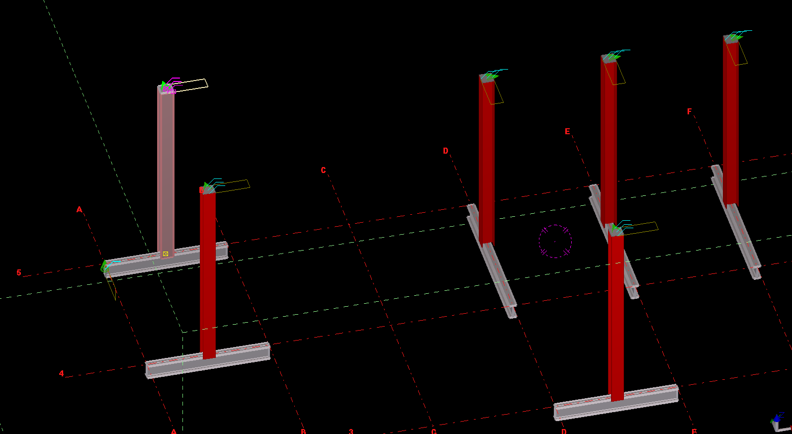
An example of us copying a column from one object, to the rest – to the rest of the beams.
What is the task at hand? We want to make the Copy Object To Object command more efficient
There is a nifty little command – little oft used in Tekla. The “Copy Object To Object” command. It’s handy, but it could be made better: all the model objects have to be selected individually. That can be a little bit of a pain. In this lesson we will create some code, using the Open API, to allow users to select multiple objects (all at once) by which the copy object to object command can be applied to.
Where is the pertinent Call in the API? I’d prefer this type of thing to be a method on the relevant ModelObject. But it’s static method in the Operation class. Here is the hello world example, straight from the documentation:
Copying Object to Object – Hello World Example:
This is fantastic! Now let us outline what we want the command to do:
What do we want our command to do?
We want the user to select an object (or group of objects).
We then want the user to select a “source” object.
We want the user to then select all objects to copy to.
The program should then use the parent object as a source, and use that as a reference to copy everything selected in step #1 to all the objects selected in step #3.
1. Ask the user to select a bunch of model objects – The objects to copy
We can use the Picker class, located in the Tekla.Structures.Model.UI namespace. And there is a handy object which thankfully has been exposed: PickObjects(Picker.PickObjectsEnum, String). This returns a ModelObjectEnumerator which we can iterate over.
2. Ask the user to select the source object:
You can get the source object in the same manner as the above code – except you would use the PickObject method instead of the PickObjects (plural) method.
3. Ask the user to select the objects to copy to:
We can use the same method used in step 1.
4. Copy from Object To Object
The rest is as easy as A-B-C:
5. Finally, we want to Redraw Views after the Copying Operation has completed
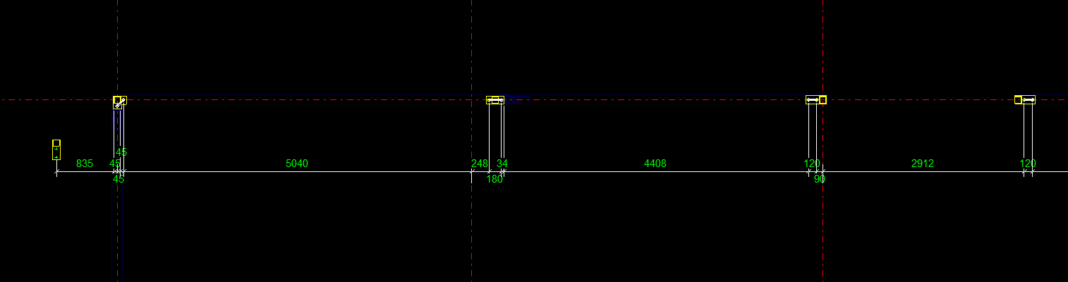
What we want to do is to select and dimension all the bolts to a particular grid line. Here’s how it should work:
* The user selects a group of bolts.
* The user selects a gridline.
* Dimensions are drawn from the Bolts to the Gridline.
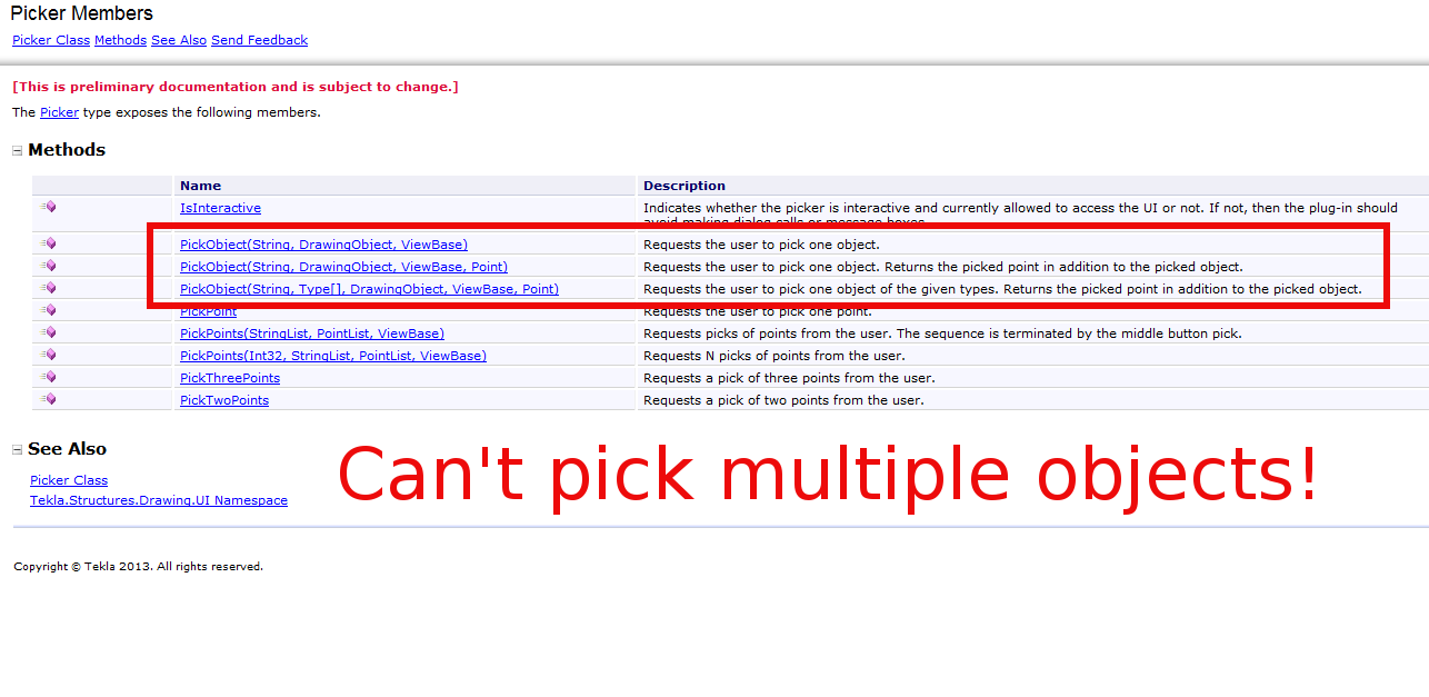
But quelle surprise – the Tekla API doesn’t expose an object which can select or pick multiple drawing objects.
What are some solutions around this problem?
We’ll we’re gonna have to be a little creative. Thankfully, Trimble have exposed the ability to programmatically obtain drawing objects. Given these objects we need to somehow filter out the stuff we want to dimension. Here are some possible ways:
We could provide a Control where we can choose and filter what objects we want to dimension, after reading/seeing it’s properties in some type of user interface (you could have a WPF application and use its fancy data binding ability + MVVM pattern + Command objects working with Service layers and Messengers) – but that would require considerable effort.
You could just select everything individually. But that would take forever.
You could extend the PickerInputWithinAView abstract method to allow you to select multiple objects.
Or you could find a way to easily filter it all. And I think I’ve found a way.
Deep in the annals of the Tekla API Reference Guide, I found that the Picker type exposes the PickTwoPoints method. And if we can pick two points, then we can certainly filter our selections.
Issues In the Algorithm We Need to Address
User picks two points.
User picks a gridline
We then filter all bolts within the bounding box of the original two picked points, and we create dimensions to the appropriate gridline. We need to understand the Drawing API.
We also need to know about saving and reverting transformation planes.
This is the hello world version of what we are trying to do, but perhaps on a scale that is a little more grand. We need some basic code on how to create dimensions.
How to Programmatically Pick Two Points
How to programmatically select a grid line
Warning – I no longer recommend this approach because it is very, very difficult to actually select a bolt. A better approach would be to select a point, and programmatically filter to get the grid line you want.
Understanding the Tekla Drawing API
Please refer to the below diagram.
An Explanation of how the Tekla API categorises its objects.
The things that you see in the drawing, are not exactly what you can see on the model. They are drawing representations of what you see in the model. If you want specific geometry based information concerning what you see in the drawing you must:
1. First get the drawing object (i.e. the drawing representation you see as a Bolt in the drawing).
2. Then you must get that same Bolt in the model.
3. You must then inquire in the model about the particular attributes or positional properties of that bolt – which is represented as a bolt in the drawing.
4. You must also bear in mind that Views etc have their own coordinate system. So if you may need to translate any differences which exist in the model to the local coordinate system of the particular view you are using. You can set and retrieve the transformation plane like so:
How to Save And Revert Transformation Planes
5. So if you need to create some dimensions, the exact lengths etc must be derived by querying the pertinent model object representations of what you see in the drawing.
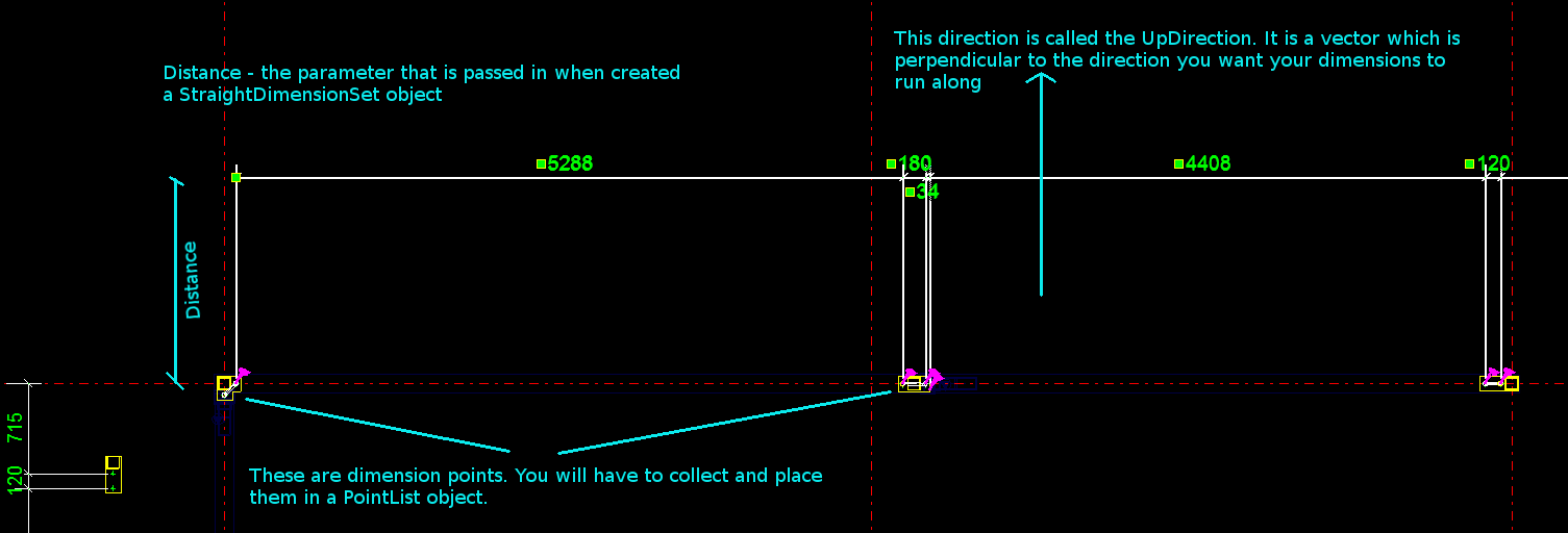
How to Create some Dimensions
The diagram provides a handy summary and visual representation of the parameters you need to pass in when creating a set of dimensions using the Tekla Open API.
How to get the drawing objects (in this case bolts) and programmatically filter them out
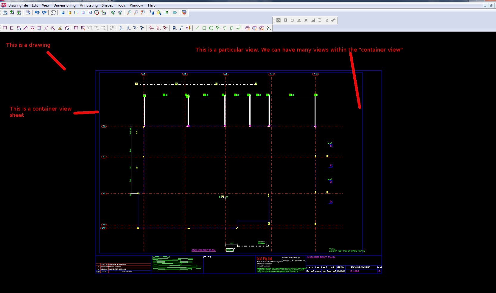
A Primer on how the Tekla.Structures.Drawing namespace is structured
Firstly you have a Drawing class. There are many types of drawing sub-classes:
Within each drawing is what is called the ConatinerView. A sheet is a container view. A container view is simply – if I were to use an everyday metaphor if you were grocery shopping – a bag which you can use to put: (i) other bags or (ii) shopping items inside. In order to get the ContainerView object, you can use the Drawing.GetSheet method – and you will be returned a ContainerView object.
Inside a container view you can typically:
* GetObjects()
* Or you can GetAllViews
* Or you can GetAllObjects of a certain type.
And within the container view, using some of the above methods you can get all sorts of DrawingObjects:
* DetailMark
* Dimensions etc
* Drawing representations of ModelObjects – like: Bolts, Connections, Grids, Gridlines, Parts, Welds etc.
Put all the elements together
If you put all the elements together, you can create some powerful little Plugins. I can’t post the full code because my boss will murder me, so I’ve done my best to teach you the key elements so you can create something powerful yourselves.