Author: admin

  • Showing an Assembly in the Model via a Tekla Drawing (Part I) – Tekla Open API Plugin

    I’ve created another Tekla plug in. And I’m calling it using a macro.

    What does this plug in do?

    Here is a demo:

    Basically it display an assembly in the model, from a given assembly drawing. Does that make sense? Well if not let’s elaborate:

    The Problem:

    I’m sure you’ll be having similar issues. So I’m working in Tekla. I’m busting my brains on this model that we’re working on, the boss is on my back like a monkey, and to add to all of that, I’m looking at an assembly drawing, but I have no idea how the actual drawing looks in real life. Can you make any sense of this?

    Can you make sense of this drawing? How does it look in 3d?

    This is simply an assembly drawing. Can you imagine how it would look in real life, or in the model?

    I guess not. What you want to see is the assembly in the model space. Well prior to my plug in, there’s a lot of rigormorale in finally getting to and seeing the drawing. Now you just run the macro and BOOM you can see exactly what that assembly drawing is referring to. In this case it’s referring to this lovely assembly in the model.

    Saves a lot of time and effort, hey?

    Ahh the glorious power of knowing .net and the Tekla API. Makes life a lot easier. But the hard part is learning programming,  .net, Tekla and the Tekla API. I suppose just save yourself the trouble and hire someone who already knows how!

    Where is the code?

    Please click here to access the code associated with this post.


    Ben Koshy

  • Structural Drafting Services

    Bendigo-Ramp
    Pedestrian Ram at Bendigo Station

    Benefits of using us for your structural drafting requirements.

    1. Experts in structural detailing and drafting who understand the needs.
    2. 45 Draftees, who can turn around you work in short time.
    3. Experts in 2d and 3d Cad systems. You get well-structured cad files and PDF prints.
    4. Lower RFIs to you at execution stage since we will dig out most of the potential RFIs and details at drafting stage. you save a ton of time.
    5. Lower costs since you engage us only when you need us.

    With many years of experience in structural and precast panel drafting, we are experienced enough to analyze your sketches and translate that into a professional set of drawings.

    We will look into potential problem areas from simple sheet naming and numbering, to connection details where required.

    If you have not provided us with connection details, we will propose the run of the mill standard Australian connection detail which you can review and approve or markup saving you a ton of time.

    The main tool for Structural drafting is Autocad for us. We also use other flavors of cad systems like Draftsight, NanoCAD, Revit

    Our CAD skills are extremely good and set up the CAD in a very systematic way.

    Services Offered

    • Co ordination with Architects Drawings
    • Creation of member schedules
    • Connection details drafting
    • Sheet layouts and Summary of sheets
    • Conflict and clash checking
    • Cross checking with design criterion (Design Criterion to be provided by structural engineer)
    • Member load taking capacity  calculation if you give the loading condtions and support conditions.
    • Preparation of structural drawings from your design brief and sketches
    • Member placement in Architects model.
    • Standard checks for Precast Panels (Lifting, spinning. Corner reinforcements,  Dowel Pins, Castin plates, Non Load bearing panels, Ferrules), Panel breaks

    Deliverables:

    • Full set of pdf drawings
    • Full set of Autocad drawings
    • Member Schedule
    • Connection details
    • Panel break up (Initial, depending upon location – Melb, Sydney or Brisbane. Other states you please supply constraints)
    • Panel break up considering crane availability.
    • Rationalisation of Panel details to lower costs. (we will liase with Architect)
    • Please download Deliverables on IFA and IFC     STEEL DELIVERABLES

    Please note – Each item on the deliverables have to be covered by a purchase order. We can work also on an hourly rate basis.

    Please note we are not structural engineers. We provide these services to structural engineers.

  • Steel Detailing

    1. Trimble Connect model with PDF of Assembly and General Arrangement drawings overlaid.
    2. Erection plan drawings.
    3. Assembly Drawings.
    4. Part Drawings.
    5. NC1 files
    6. DXF files
    7. unwrap templates
    8. IFC model – after payments have cleared.
    9. Trimble Connect Model with GA and Assy drawings overlaid
    10. CAD files of Erection plan and Anchor bolt layouts.
    11. Total Station export of Anchor bolt locations.
    12. Reports
      • Material List
      • Assembly List
      • Part List
      • Assembly Part List
      • Purlin List – (Purlin Bundles)
      • Bridging List
      • Galvanizing List
      • Erection bolt ListBolt Summary
    If requested at quote stage 
    Delivery of following Items incur significant detailing cost.
    1. Advance Bill of material
    2. Weld Map Drawings
    3. Detailed notation of each Weld
    4. Custom Drawing Templates.
  • Create accurate grid from converted PDF Files

    This  tool works with Autocad. Usually the architects grid is not accurate to the decimal point for detailing purposes. Most detailers redraw the grid more accurately.

    This API tool let you select text in autocad and draw the grid automatically. Usually a pdf file converted to autocad is sufficient.


  • Careers and Training at Tek1

    Jobs for Fresh Graduates at Tek1

    Tek1 is offering tutoring services at a cost to learn Tekla and basic steel detailing at a small fee. You can download Tekla software from Tekla Campus, learn at your own pace to a set curiculam.

    When you are ready to take up a job with us come in for an assessment. If you pass the grade, we will offer you an employment on a probation basis for 6 months. If you successfully complete the probation, then we will offer you a full employment at wage which is the best in the Industry.

    If you do not wish to take up an employment with us but wish to get a certification then we will issue you with a certificate of completion.

    Please note that we do not hand out certificates. To pass our test you have to put in some serious effort.

    For more information email us on info@tek1.com.au


    How to arrange for an Interview

    Please follow the flow chart.

    Important

    Following the instructions on how to apply for the position is an important part of our screening process. Steel detailing inherently requires detailers to have attention for detail. If you cannot follow the instruction on how to apply for the position, you will likely struggle as a detailer. So our screening process starts right at the point of submitting the application.

    You will be required to take an online test from your home at your convenience as the first part of our selection process.

    Once you pass the first test, you will have to come in for another test in our office. This second test can be organized in Kochi as well.  If you get good score and then pass the immediate personal interview, you will be made an offer on the spot.

    The fact that you were made an offer , indicates that you are likely to succeed in the job. However there are further milestones you will have to cover before you will be offered a permanent position. (Mainly to do with how well you complete the training and probation period).


    Tek1 Offers  Tekla Training

    To be eligible.

    • You must have a diploma or degree in Engineering (Mechanical, Civil, Structural, Arhcitectural)

    Autocad Drafting

    We provide Autocad Drafting training.


    Fees may apply.

  • Tekla Plug-in #1: Multi Drawing Selector

    Multi drawing Selector for Tekla drawings

    The Multi Drawing Selector Application is a program helps collate the single part drawings of all parts (with the same profile) into a single multi sheet drawing.

    If I have a certain profile of flatbar: say 90×10 then wouldn’t it be handy if I had all such flatbars (with their varying lengths) on a single drawing? In the past you would have e.g. 16 different drawings (one for each particular length of the 90×10 flatbar) jumbled all over the place in your folder. If you had to fabricate it then you would have to sift through the folder for all such profiles. Having obtained the 16 different drawings, then you would go to your factory and obtain the 90×10 flatbar and produce the 16 different types of flatbars you need. But what if you did not see a 90×10 flatbar drawing at the back of your folder? What if there were 17 different drawings for that particular profile and you only pulled out 16 from your folder to take with you to the work shop floor. So basically you forget to fabricate a single part. But what if you were required to make 14 of those? When you find out, then you would have to go back into your work shop, get a flat bar and make the cut again and make 14 flatbars that are 90×10 with that particular length. Ideally you’d want it done correctly the first time, but now you have to make two different trips. And we are only talking about one particular profile here.

    Now you can dramatically reduce the number of drawings you have in your folder. 90 x 10 flatbar? No problem. Simply pull out the multi drawing which already has everything within it: take it to your work shop and cut all the required flat bars there. No flipping back and forth. You won’t miss a part – because it is ALL there, and you won’t be forced to redo it at a later stage.

    What exactly does it do?

    It looks through your model for all standard sized flatbars.
    All unique flatbar profiles will be written down separately in a “list”. For example, let us consider the following flatbar profile: 90×10. Suppose you have 10 such profiles in your model. This particular profile will be written down on the list, along with the 10 single part drawing numbers of associated with that particular flat bar.
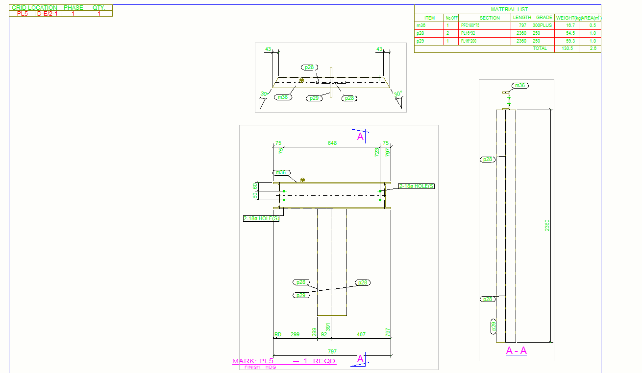
    If your model has non-standard flatbars, or plates, this will be collected and highlighted separately in a “plate list”. e.g. suppose a detailer creates a FT 91.3 x 11.1 profile. This will be written down on the “plate list” with all the part numbers associated with that profile.
    The program allows you to select all the parts associated with a particular profile. In other words, you can select all the 10 parts associated with that 90×10 profile, and you can put them in one single multi drawing.

    It takes about 45 seconds after clicking the refresh button for the list boxes to be populated.

    Instruction on how to use.Tekla must run first

    Tekla must run first

    Single part drawings must exist
    You must apply the correct selection filter.
    You have configure a .CSV file which lists all standard flatbars in the correct format.
    Start flatbar application
    Click refresh button.
    Double click profile on right lefthand side to see the drawing Nos.
    Select Drawing Nos
    Click Select button
    Now switch to Tekla window and create mulit drawing for selected parts
    Benefits

    Items are selected by Profile and in increasing length.
    The number of drawings associated with a particular profile is placed in brackets around the profile dimensions. e.g. 100 x 16 has 17 different part numbers and single part drawings.
    If you’ve already created a multi drawing for a particular part, then it won’t show up in the list again, after you’ve pressed refresh. That way you will know exactly what parts need to be placed in a multi drawing and what parts have already been placed in a multi drawing.
    Saves everyone a lot of time and headaches.
    If you require the macro please email the admin or email info@tek1.com.au
    The flat bar picker is customised for the Australian environment

    Multi Drawing Selector

    If you require any custom tools in Tekla, Autocad please contact us.

    Also any applcations using Ruby on Rails, dot net or Php. (We prefer ruby on rails for web applications)

  • Check for Loose Parts In Tekla

    From the View properties, select “Loose parts” from the drop down. Loose parts will be shown in red.

  • Changing colors for model dimensions

    Default colors for model view dimension check is not very good.

    You can set the model view dimension in advanced options

    Please go to advanced options->Model View -> XS_VIEW_DIMENSION_LINE_COLOR. Set value to 1.1.1.1.1.1

    also value of

    XS_VIEW_DIMENSION_TEXT_COLOR to 1.1.1.1.1.1


  • Lock X, Y, Z co ordinates.

    Do not put a custom short cut of x, y and z keys.

    Default behaviour of x, y and z keys in Tekla is to lock X Y and Z co ordinates.

    Try this keys.

    Once the default keys are set to override, then undoing that is not easily possible.