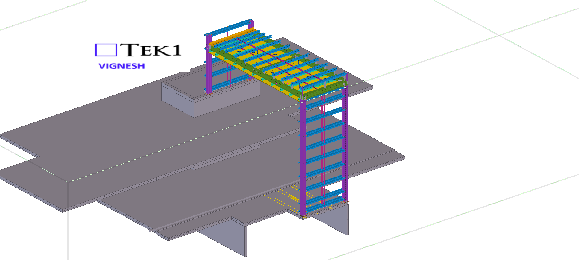
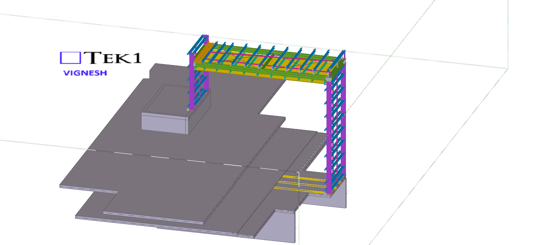
We are proud to be a part of the team in Marymede Planter box project.
Our detailing team worked closely with architects to ensure tolerances and offsets were met without compromising design intent With a limited fabrication and erection window, our detailing team adopted a fast-track workflow using Tekla Structures for 3D modeling.
This allowed us to provide early shop drawings for procurement and parallel review of sections still under coordination.
Our detailing team worked closely with architects to ensure tolerances and offsets were met without compromising design intent With a limited fabrication and erection window, our detailing team adopted a fast-track workflow using Tekla Structures for 3D modeling.
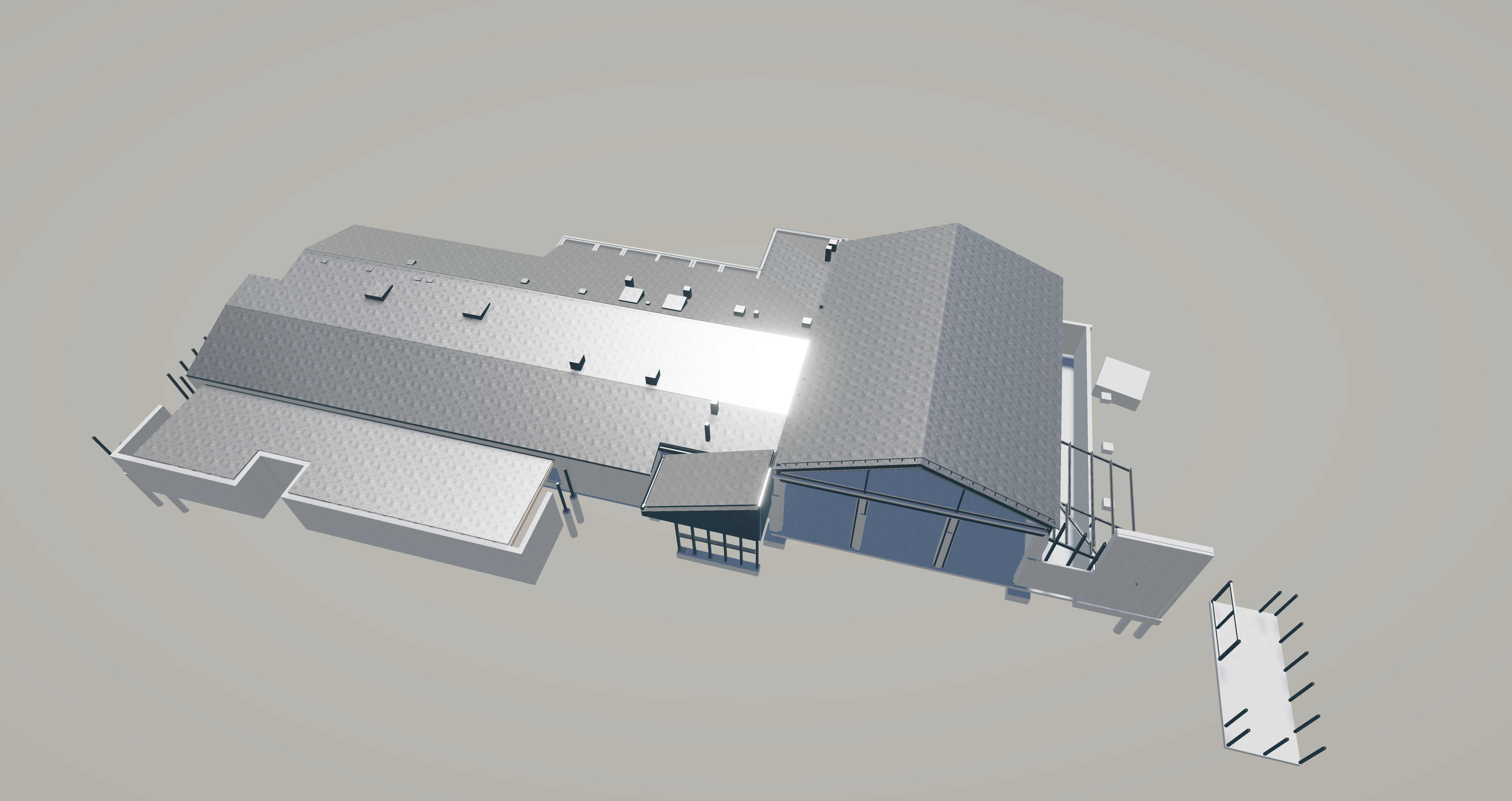
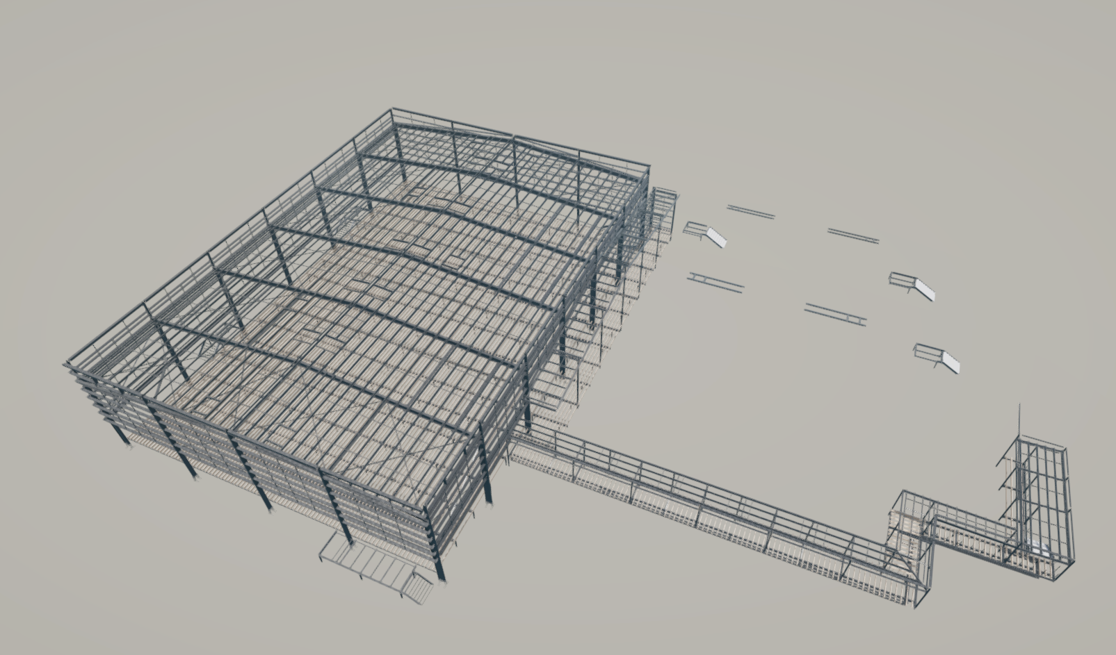
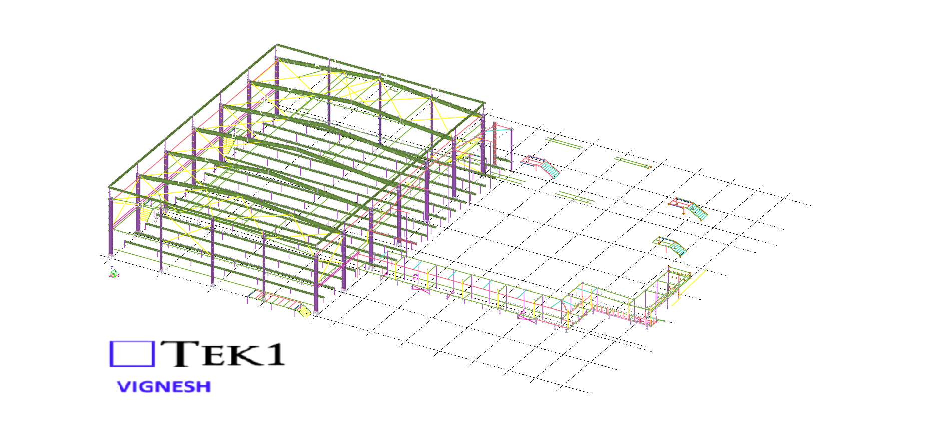
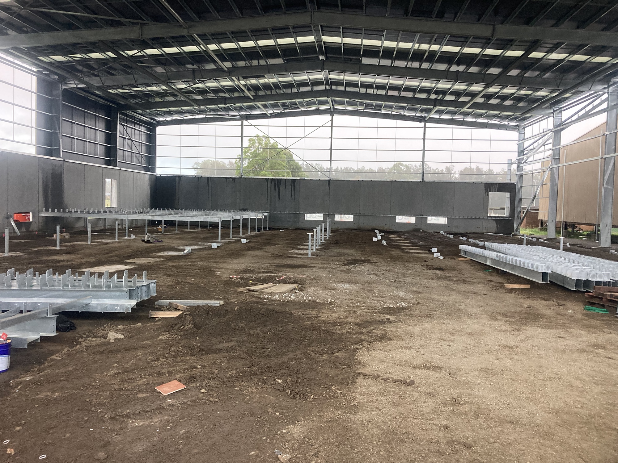
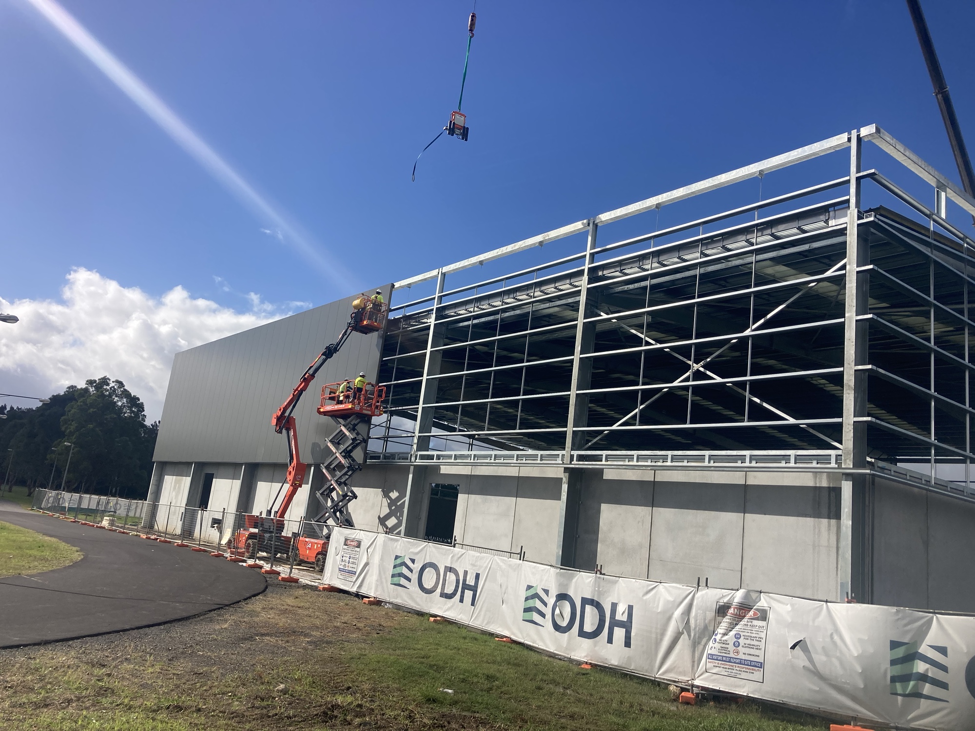
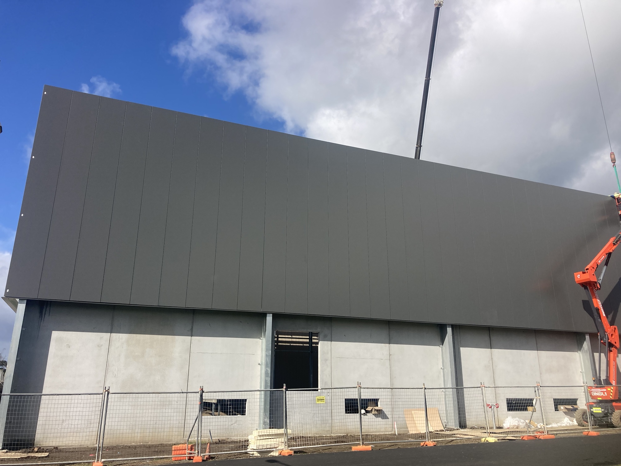
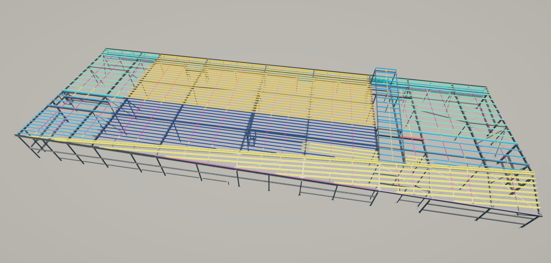
We are proud to be a part of the team in IRON_ARENA_SPORTS_CENTER project.
This allowed us to provide early shop drawings for procurement and parallel review of sections still under coordination.
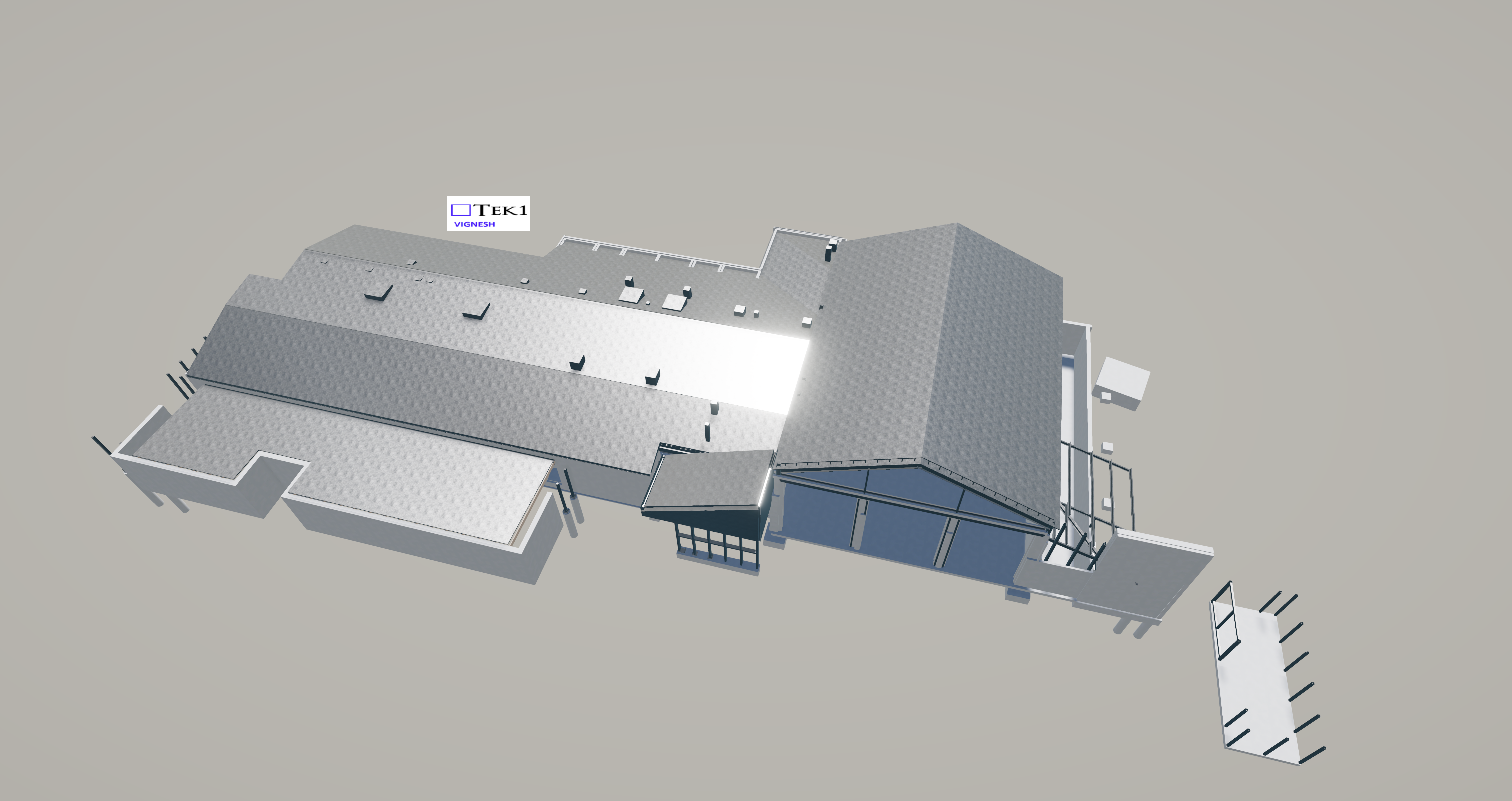
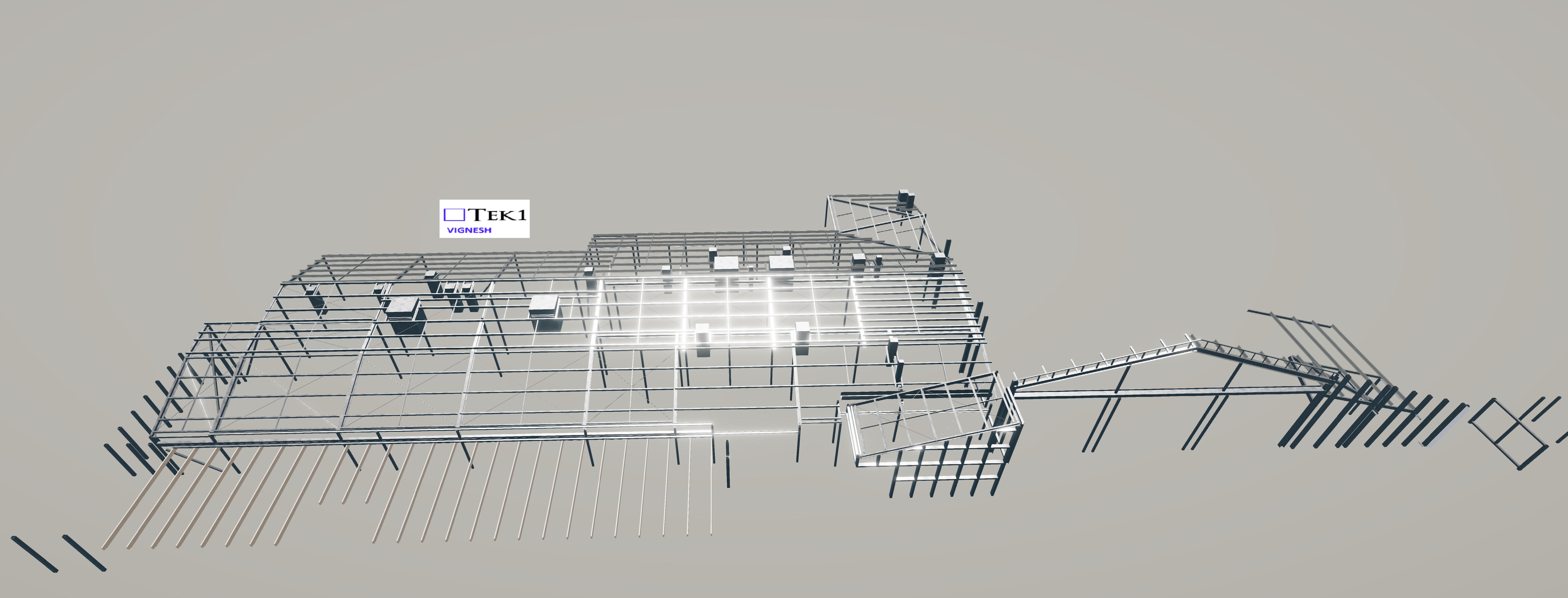
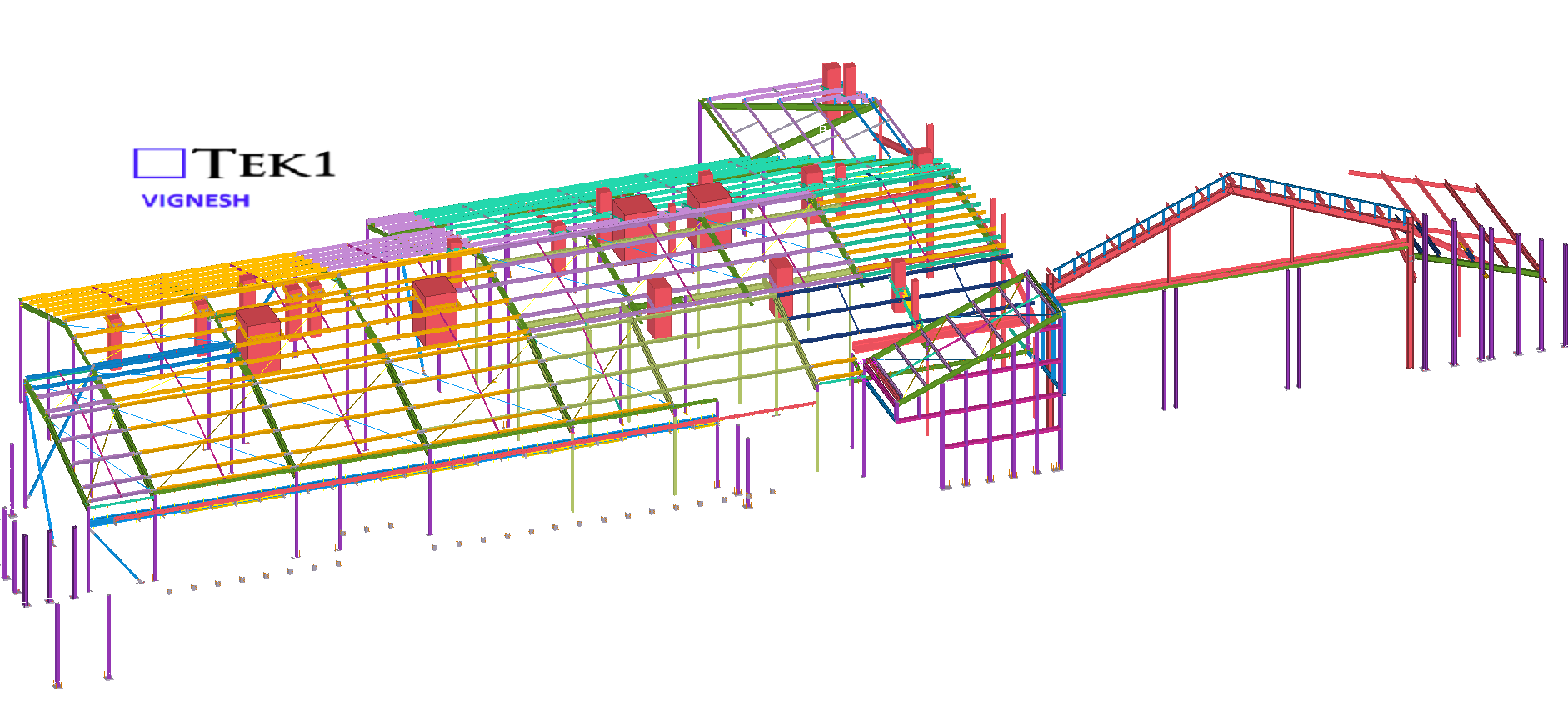
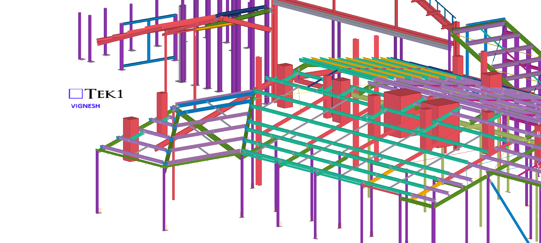
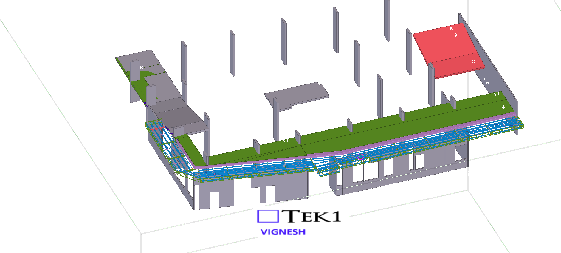
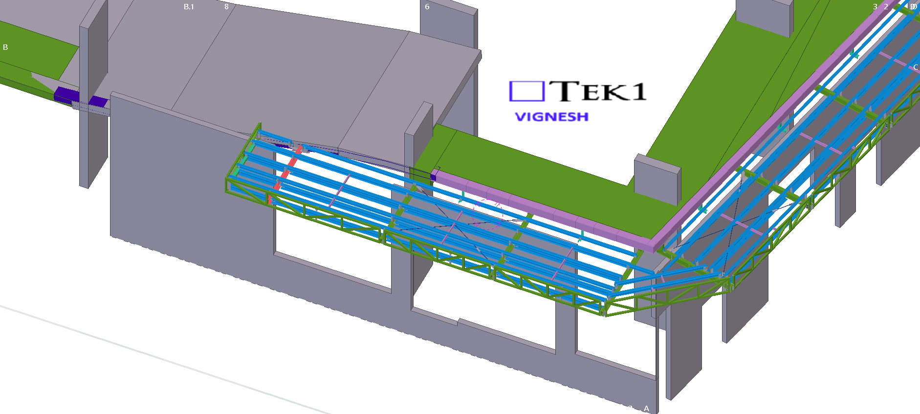
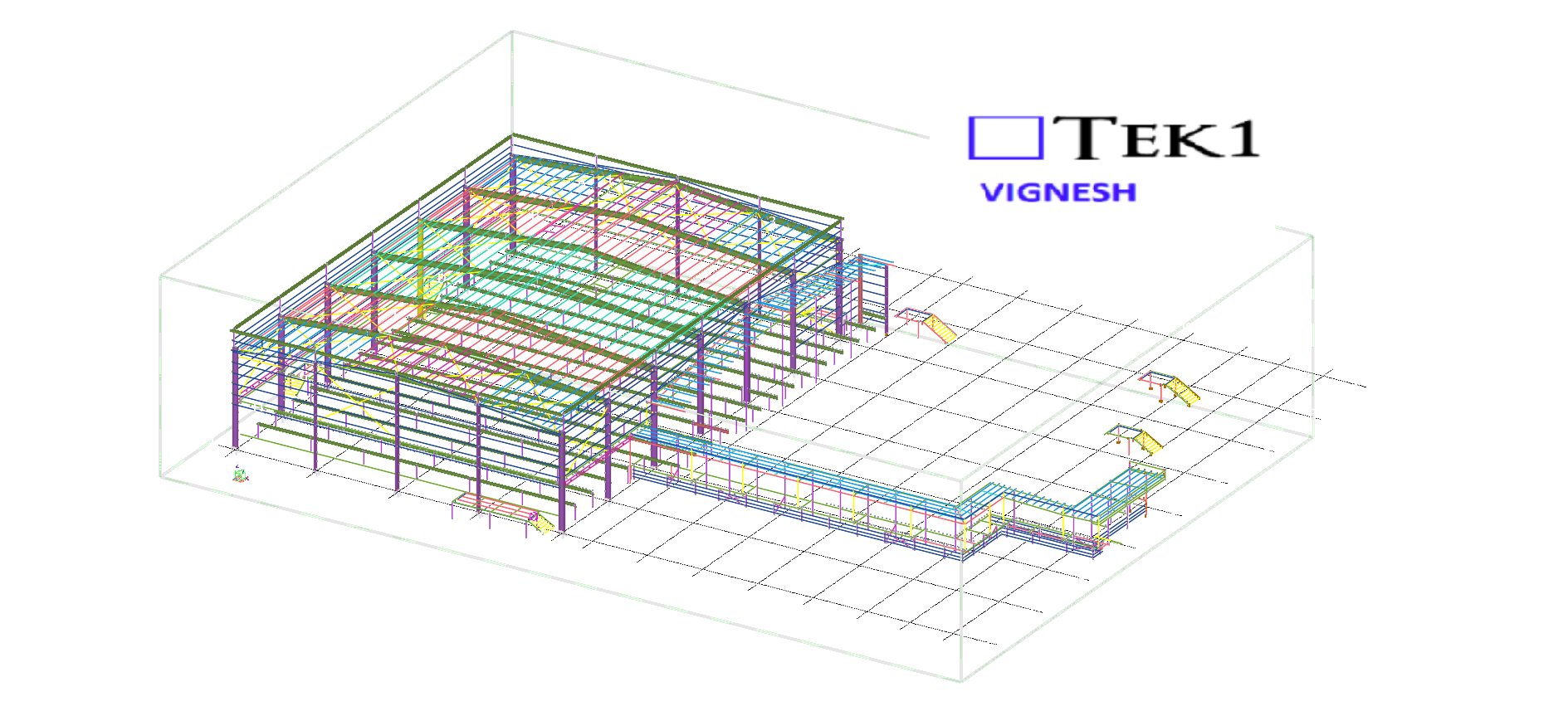
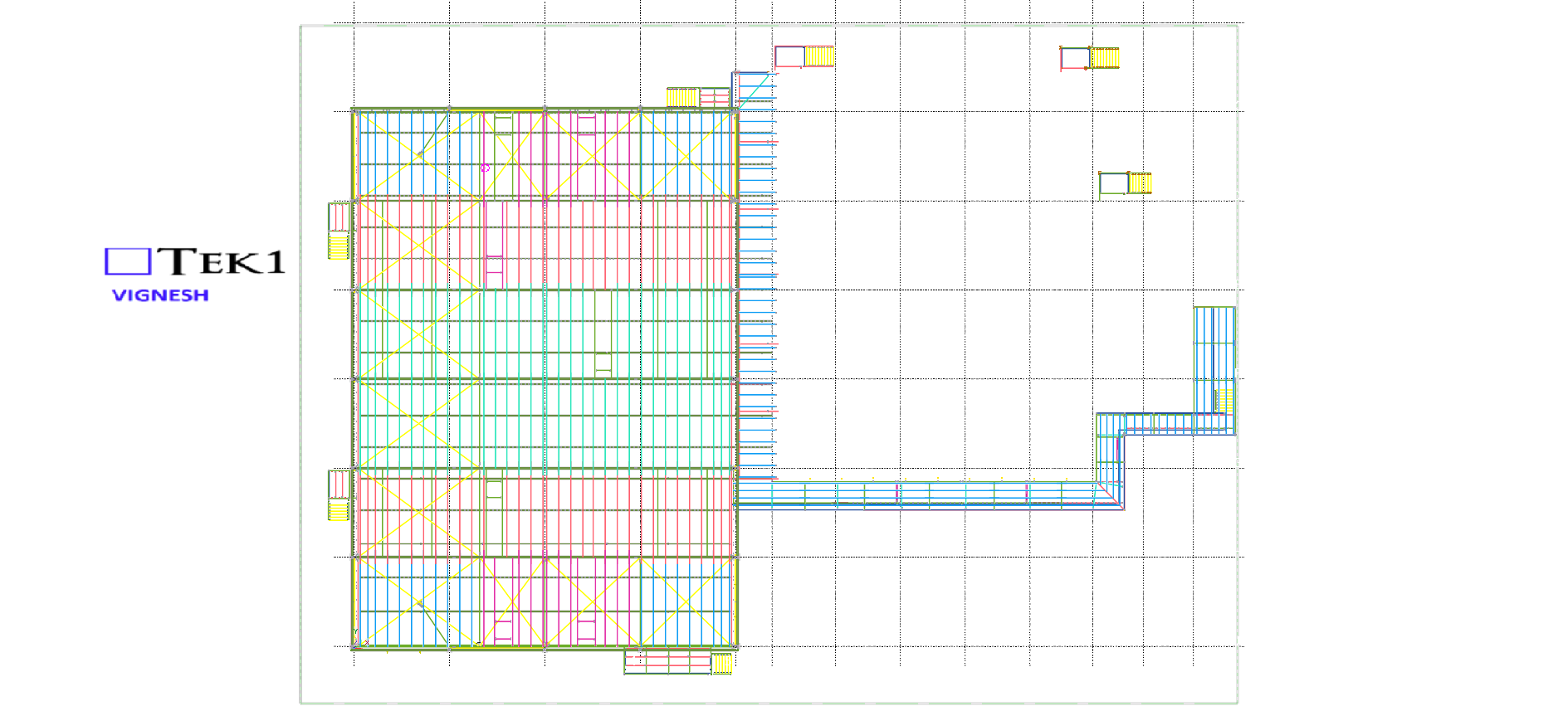
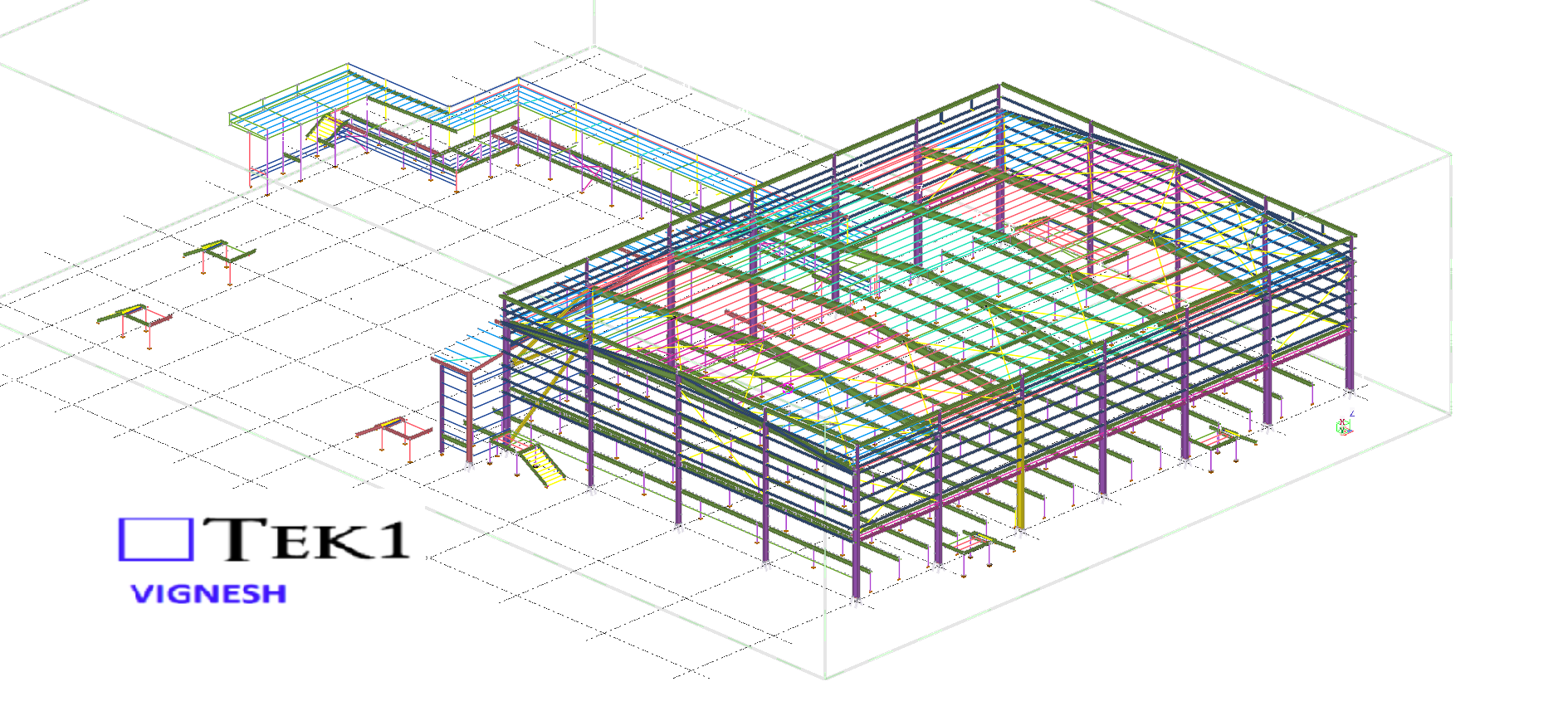
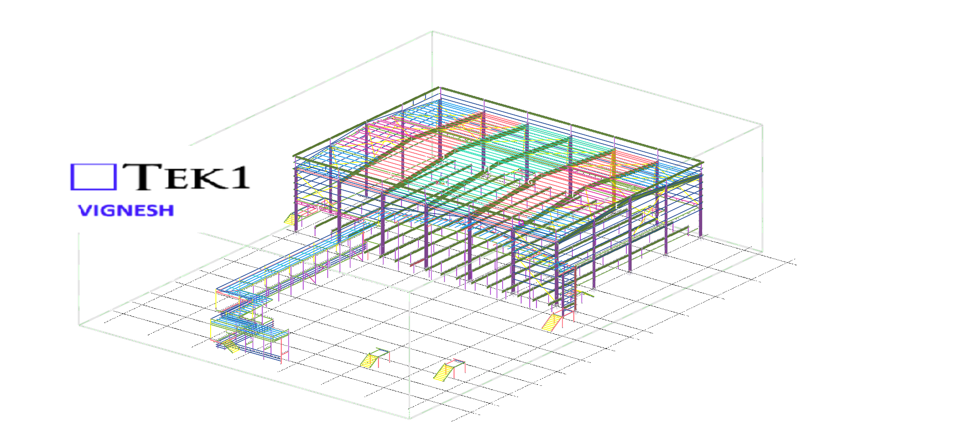
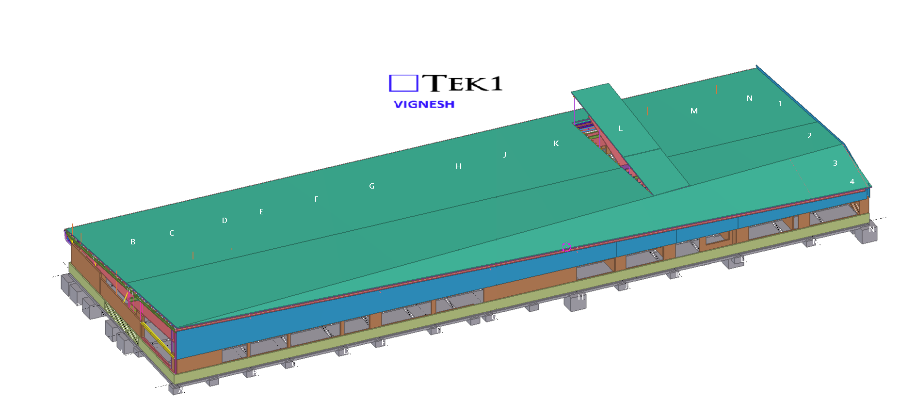
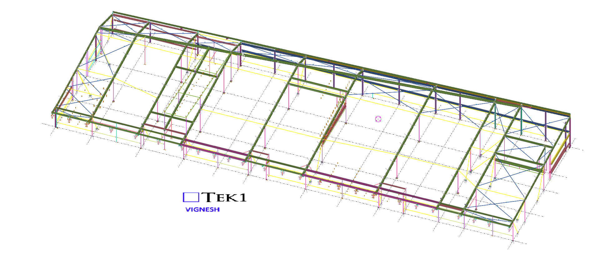
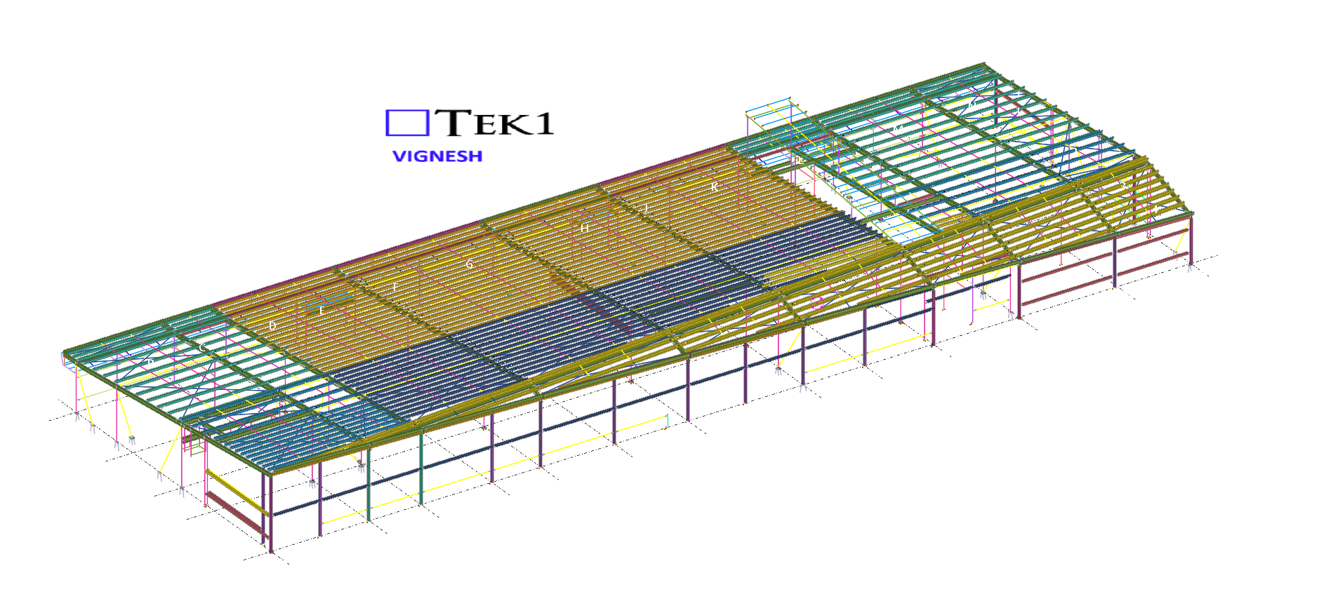
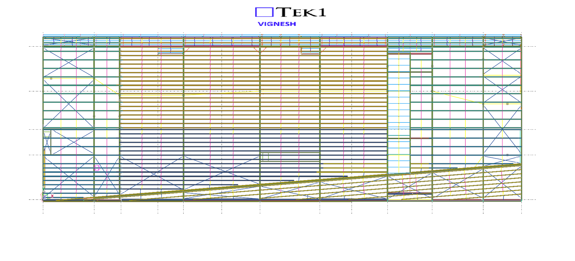
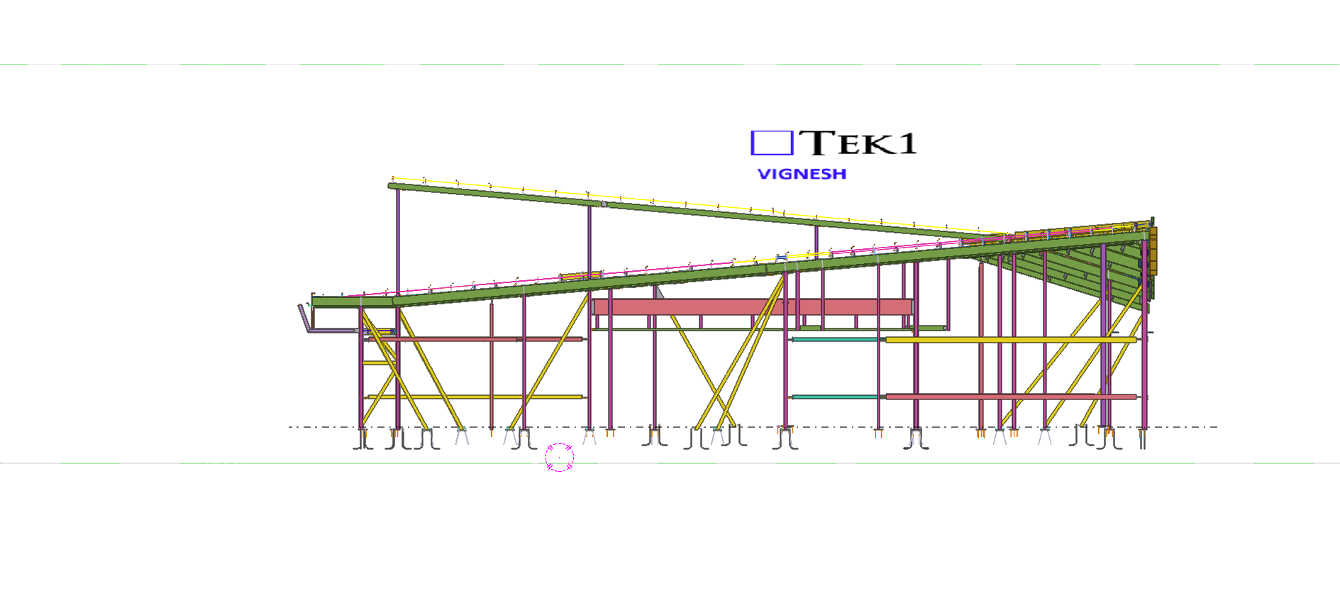
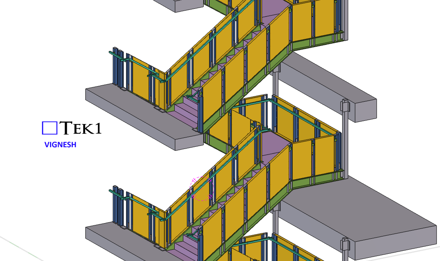
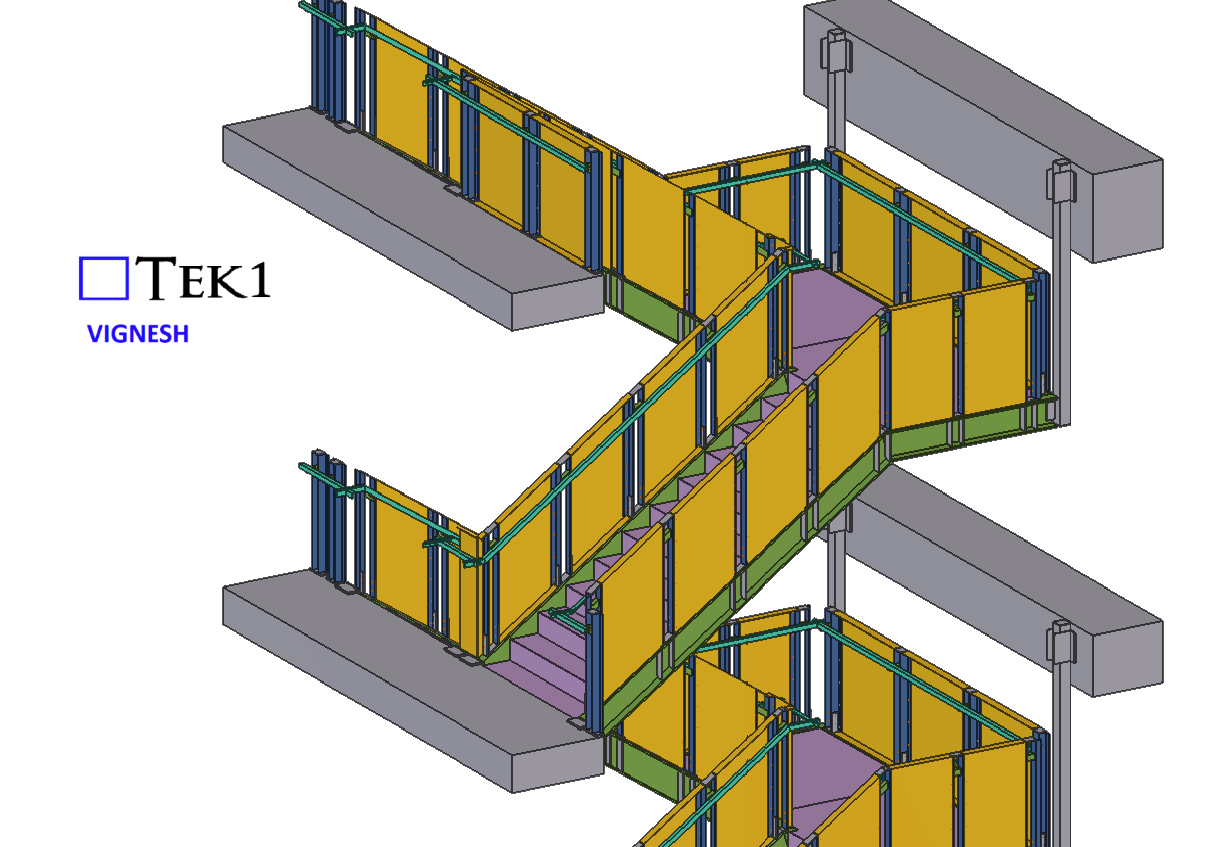
We are proud to be a part of the team in VSBA School-51 project.
Our detailing team worked closely with architects to ensure tolerances and offsets were met without compromising design intent With a limited fabrication and erection window, our detailing team adopted a fast-track workflow using Tekla Structures for 3D modeling.
This allowed us to provide early shop drawings for procurement and parallel review of sections still under coordination.
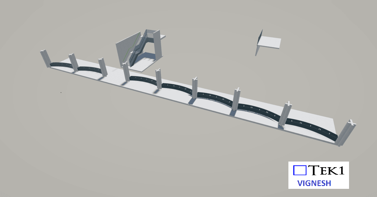
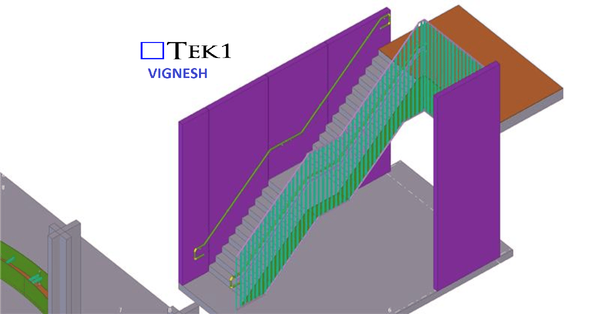
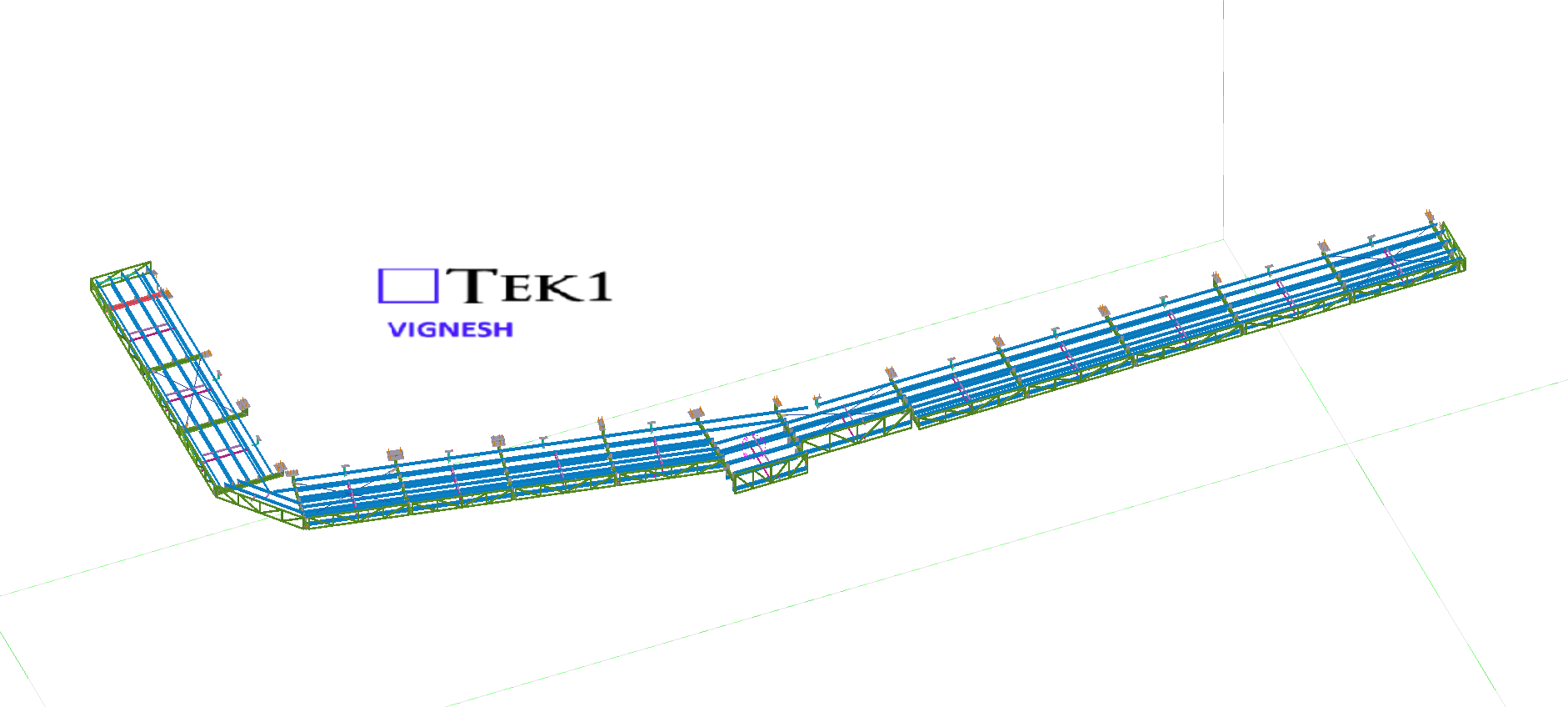
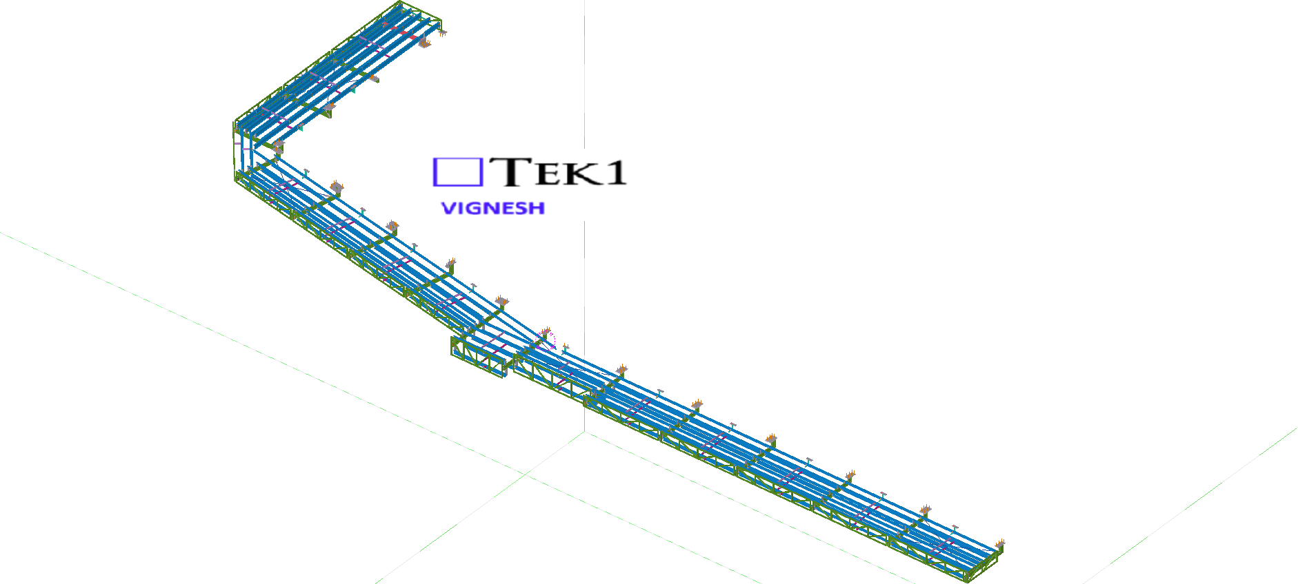
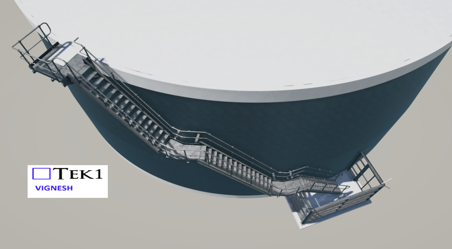
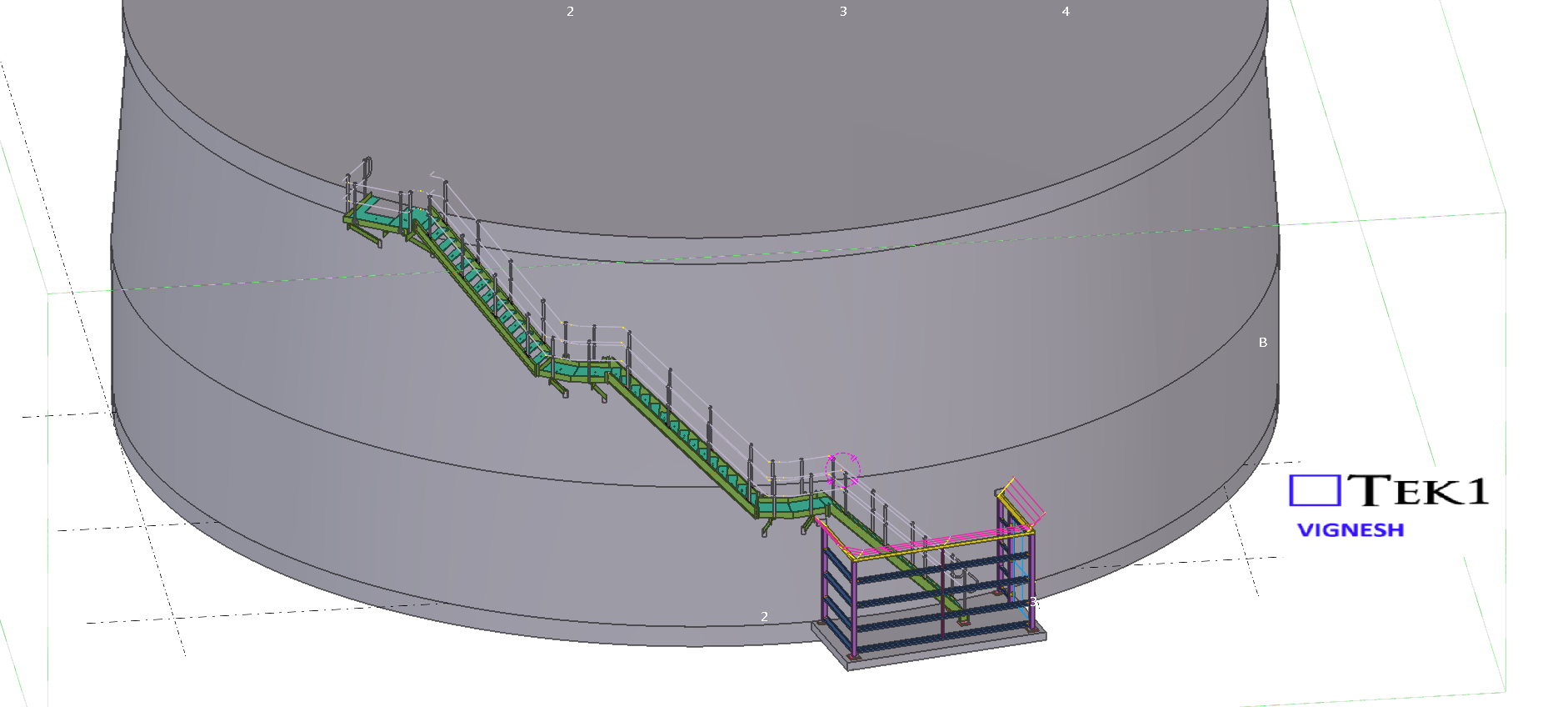
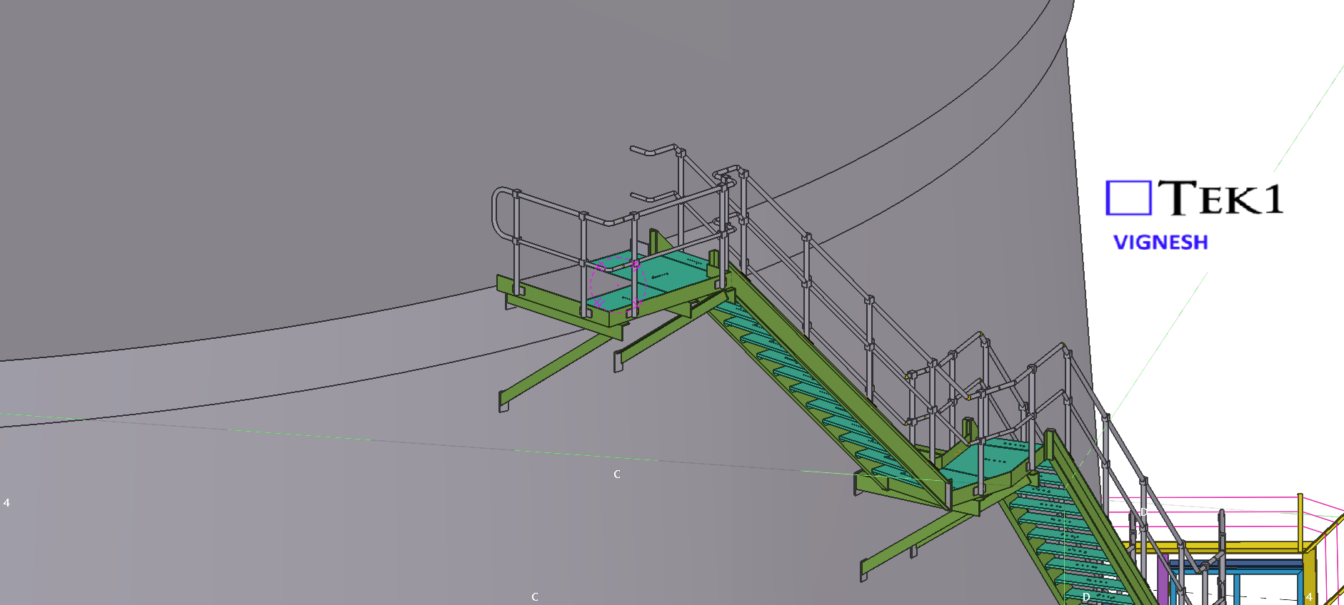
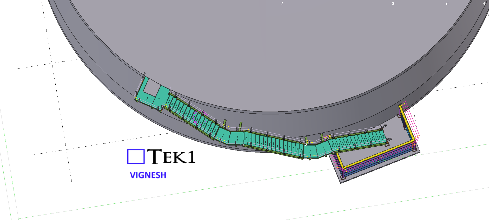
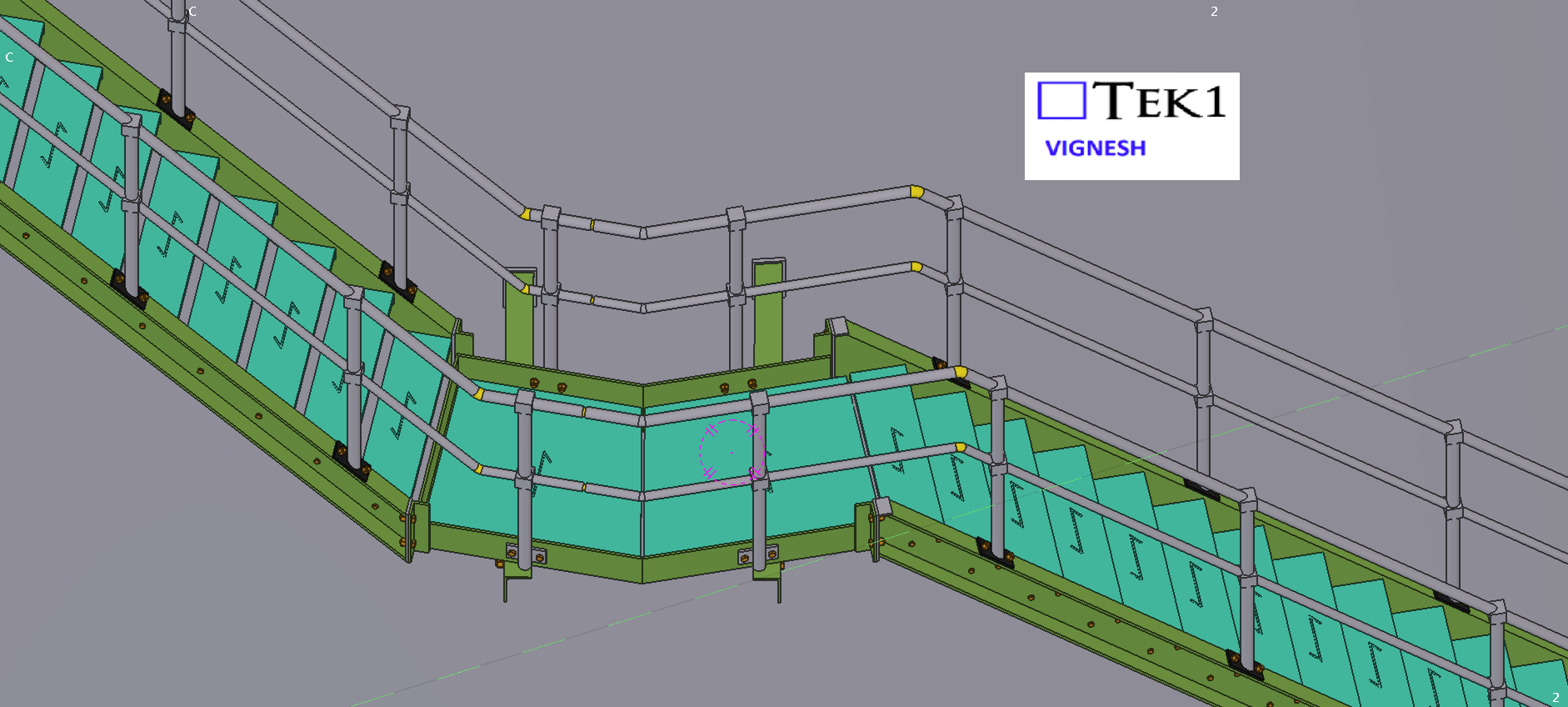
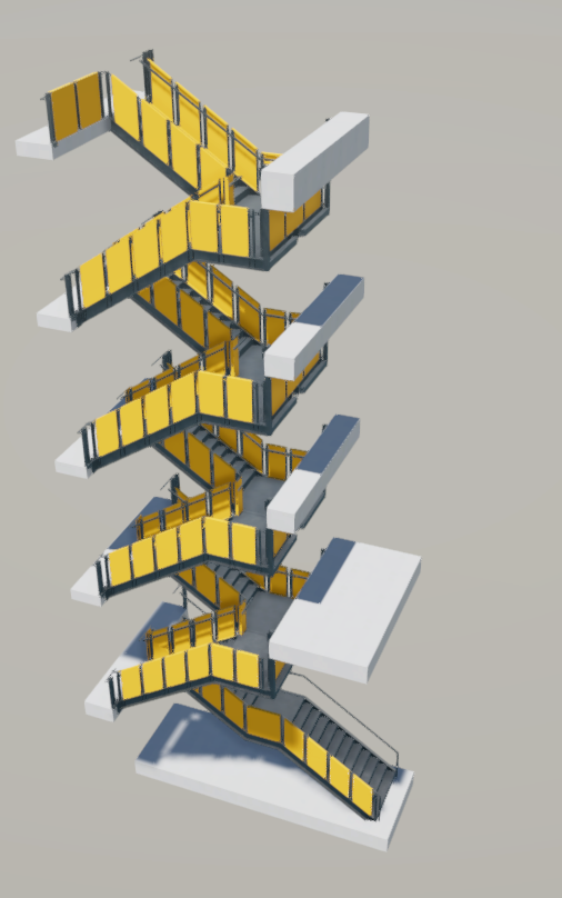
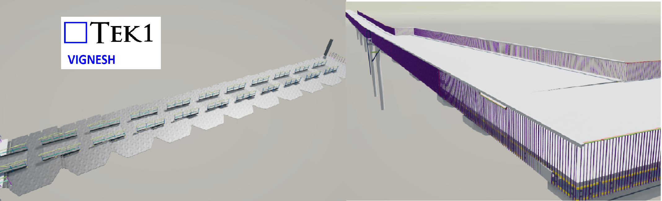
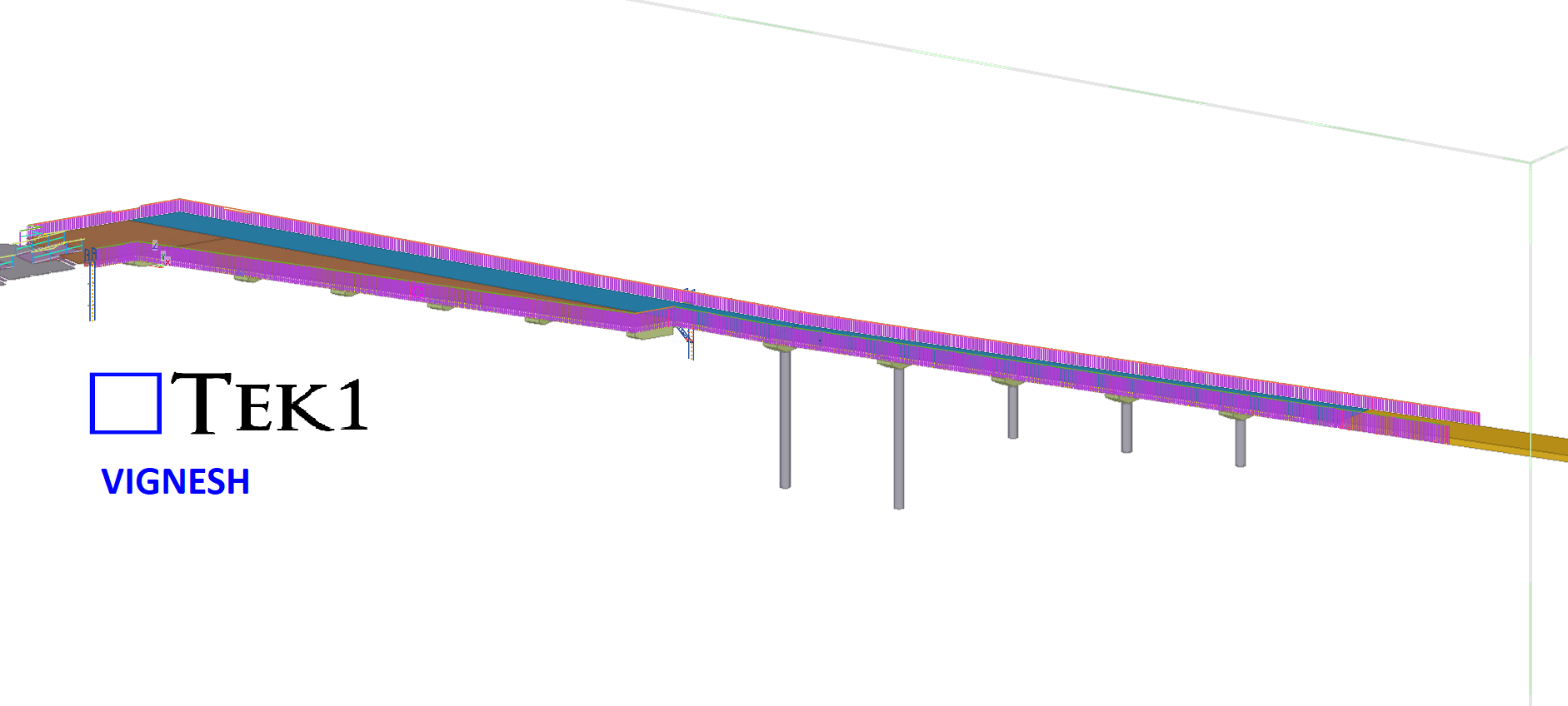
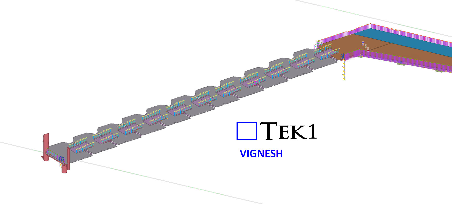
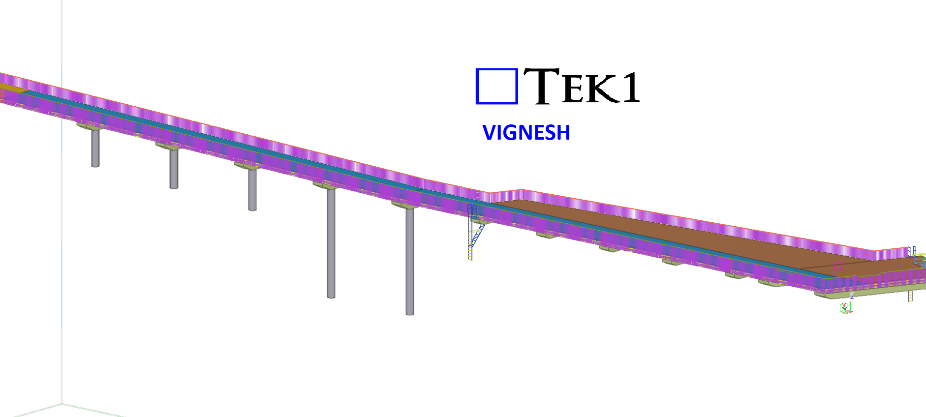
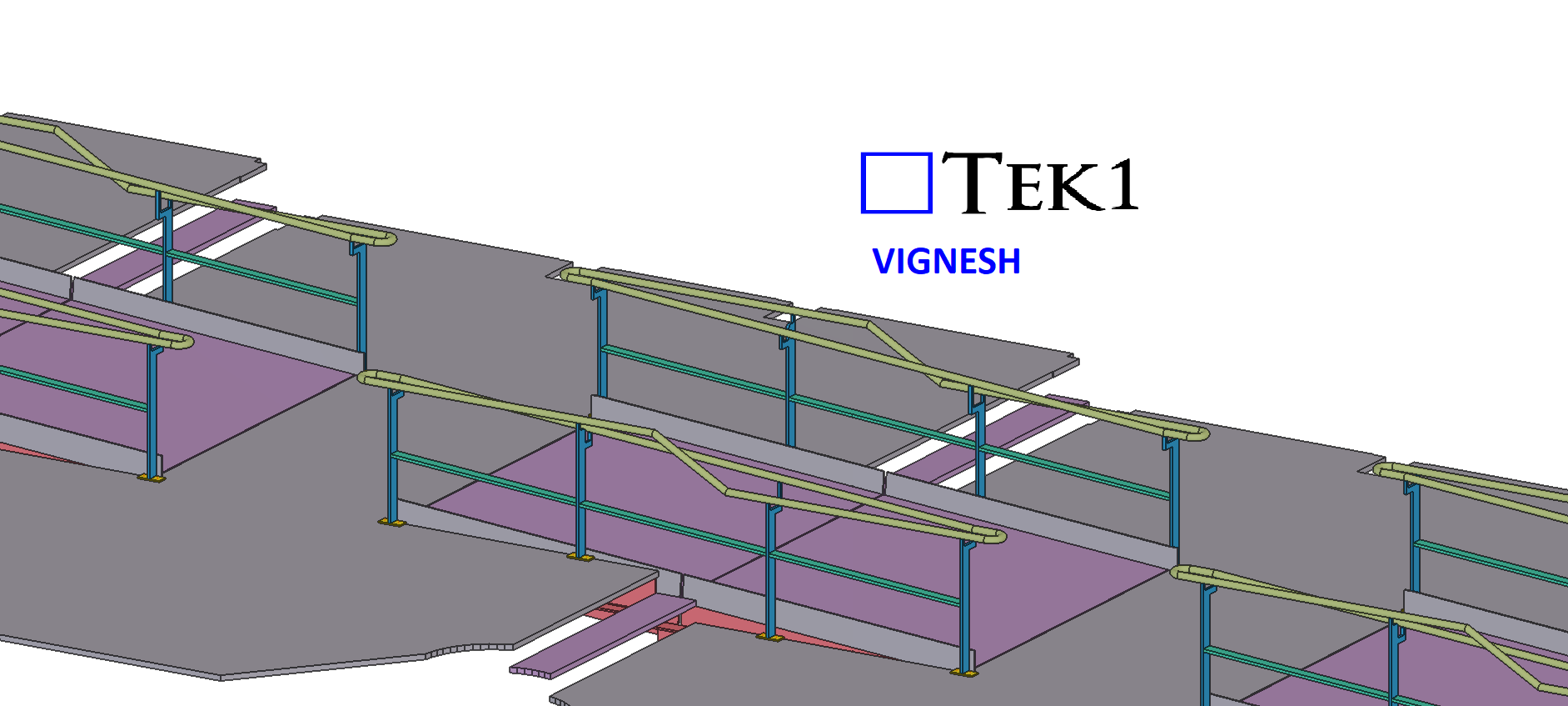
This was a complex project, but we successfully delivered it. Our scope included the balustrade around the bridge, which needed to be provided in multiple panels. By utilizing advanced modeling techniques, we were able to complete it within a significantly shorter timeline.
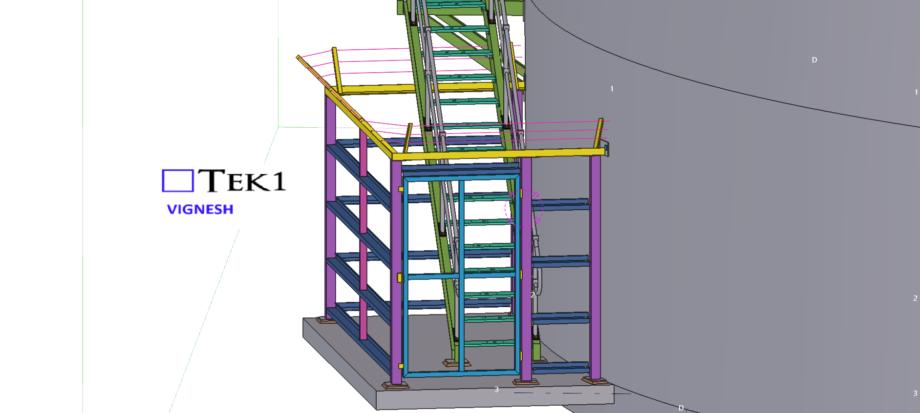
Since the structure is above the sea, we provided several cost-saving ideas for both erection and fabrication to optimize the process.
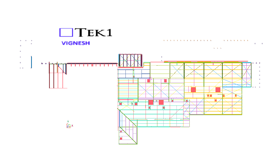
This was drawn by Tek1 (Vignesh), if you want shop drawings for a project you are working on, feel free to call Koshy on: (03) 9560 6397.
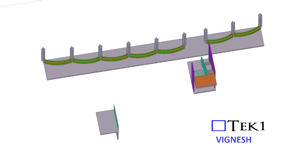
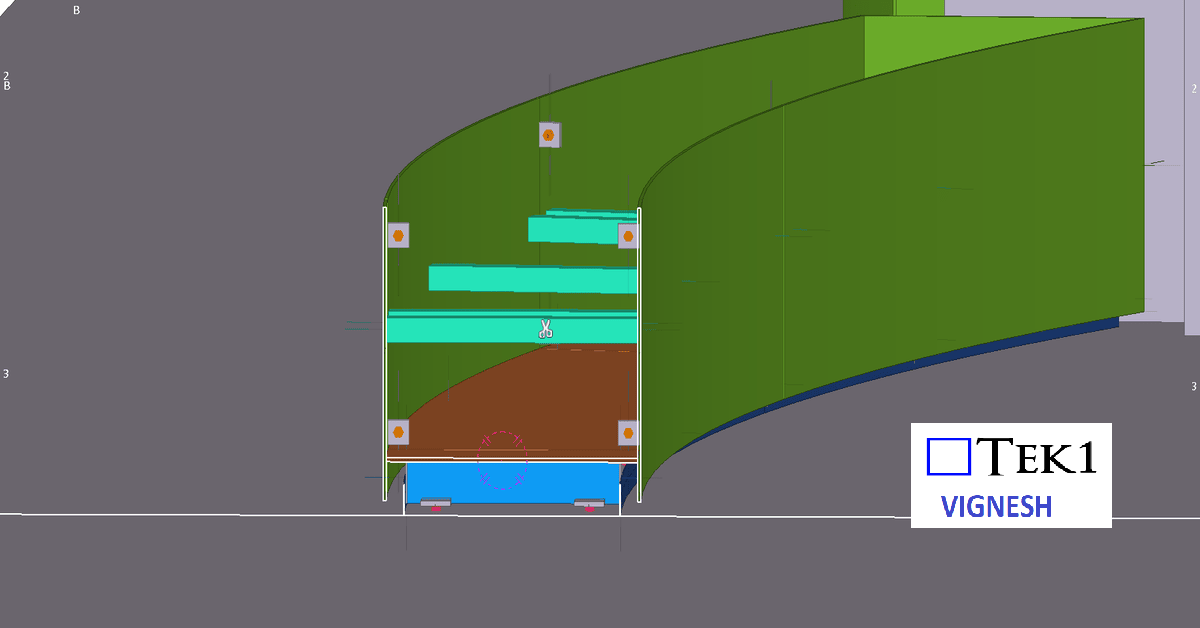
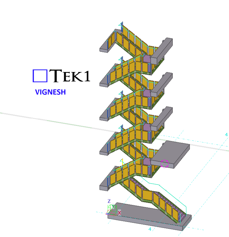
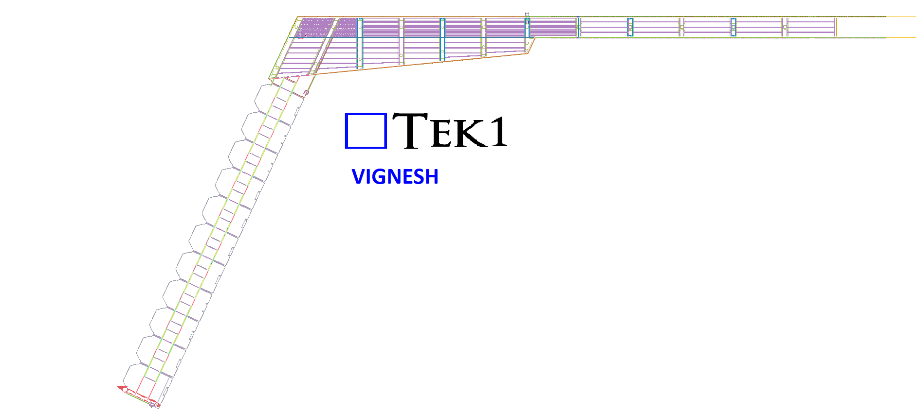
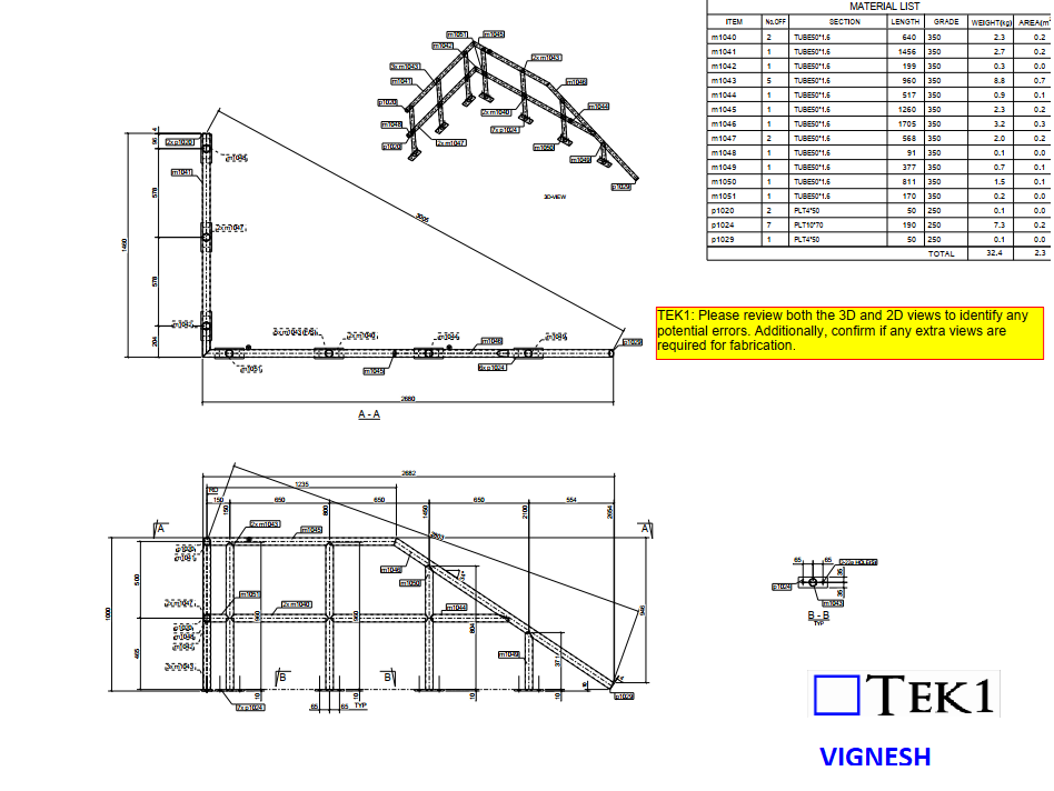
Please review both the 3D and 2D views to identify any potential errors. Additionally, confirm whether any additional views are required for fabrication.
Sounds fine, right? But here’s the catch—is it actually possible to fabricate with these views?
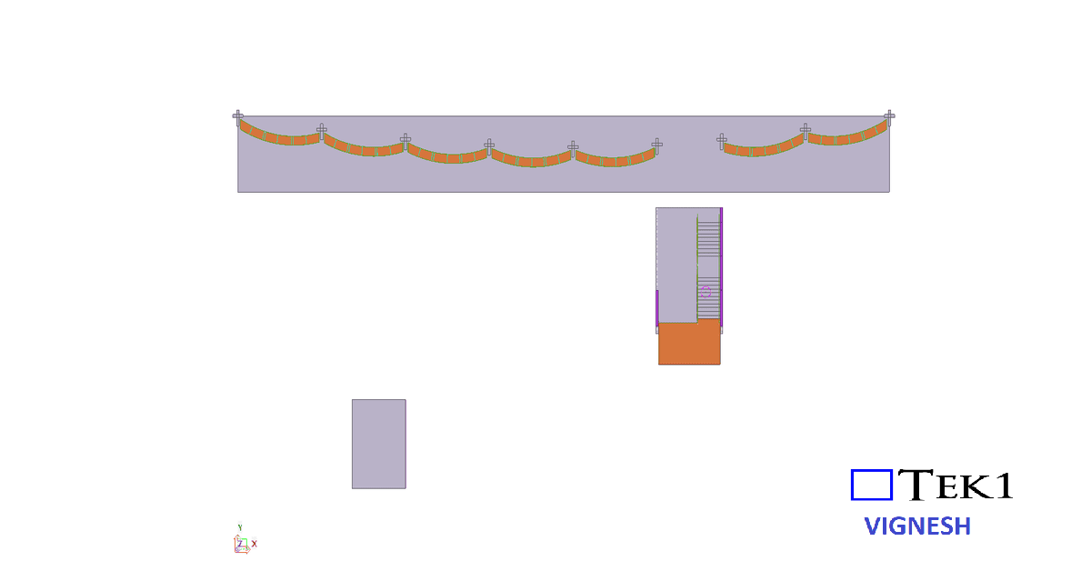
The Hidden Problem
If we fabricate by 3D view alone, there might be a potential error. In reality, the fabrication needs to be done upside down.
Fabrication Assumption: The 3D view is correct, but the plan & elevation view is incorrect.
As a result, the fabricator may assume the wrong orientation and fabricate it incorrectly.
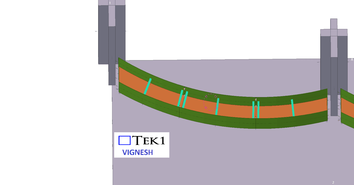
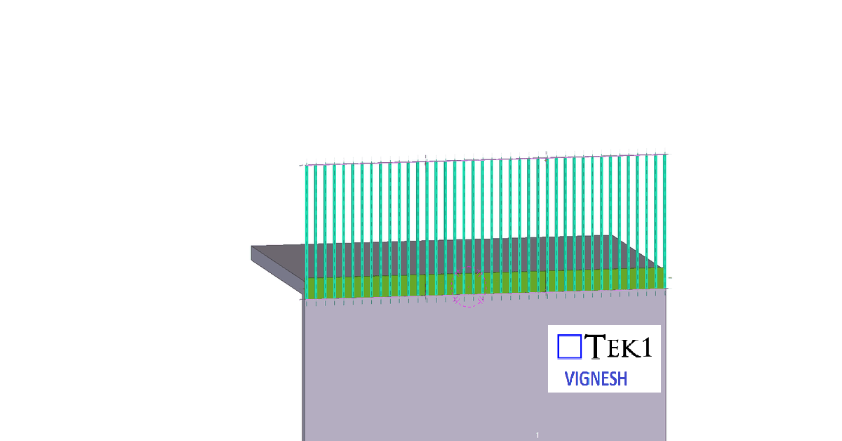
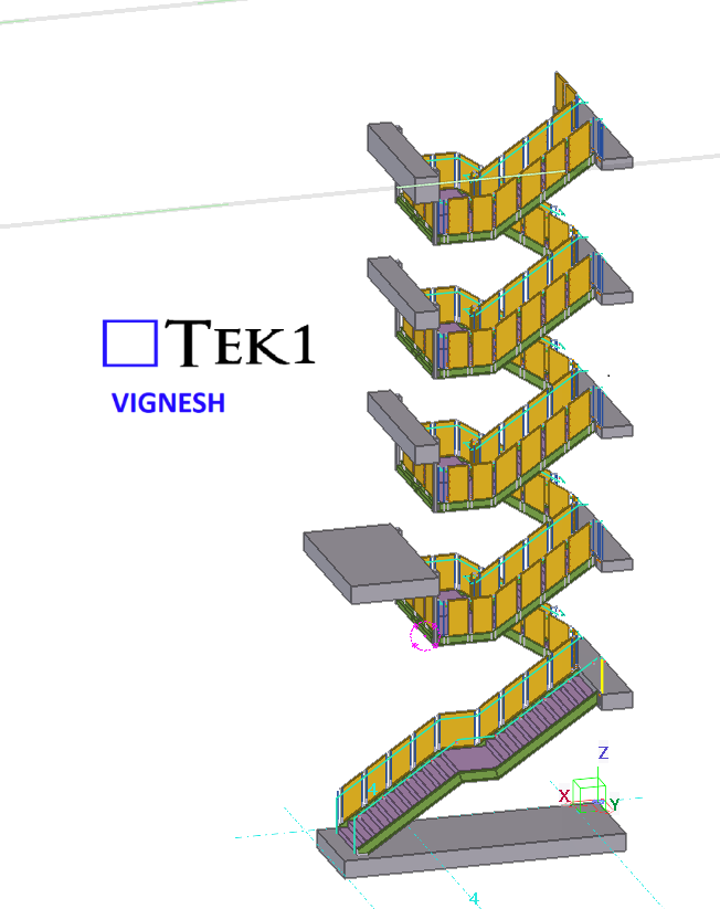
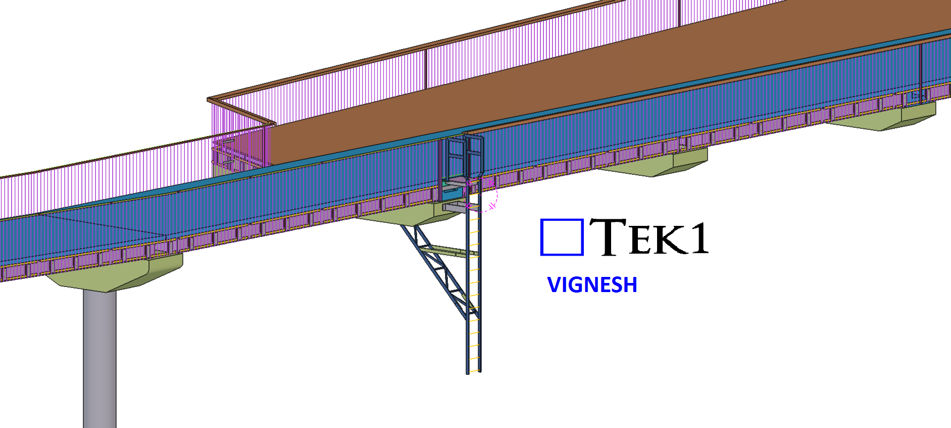
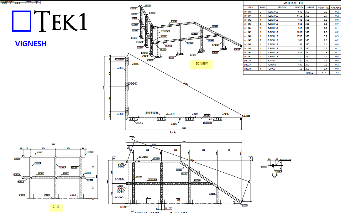
The Right Approach
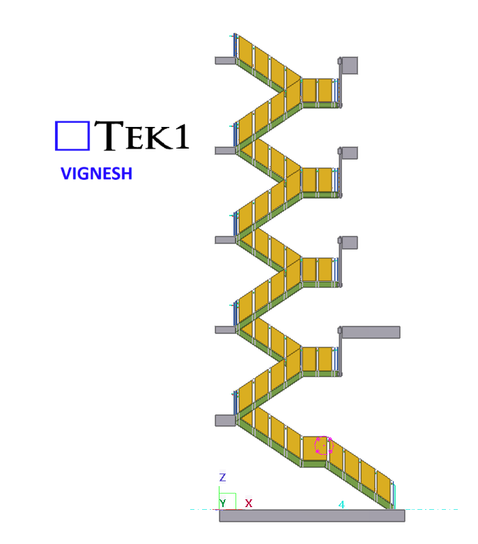
We need to provide an additional section view C-C and ensure the 3D view is correctly oriented.
Actually, in the above drawing shows, the 3D view is placed as the underside view, which may visually appear as downside up.
Please review correct drawings attached below.
Always make sure any potential confusion is resolved before starting fabrication.
So next time you see a similar detail, take a closer look—is it actually can fabricate?