Author: Vignesh Selvaraj

  • A detailers’ guide to sheet metal bending

    This blog illustrates how to provide the dimension detail in an efficient way for sheet metal bending using Tekla Structure. For bending of sheet metal, we need to provide add-on information in Pdf drawings and dxf files for calrity of fabricator.

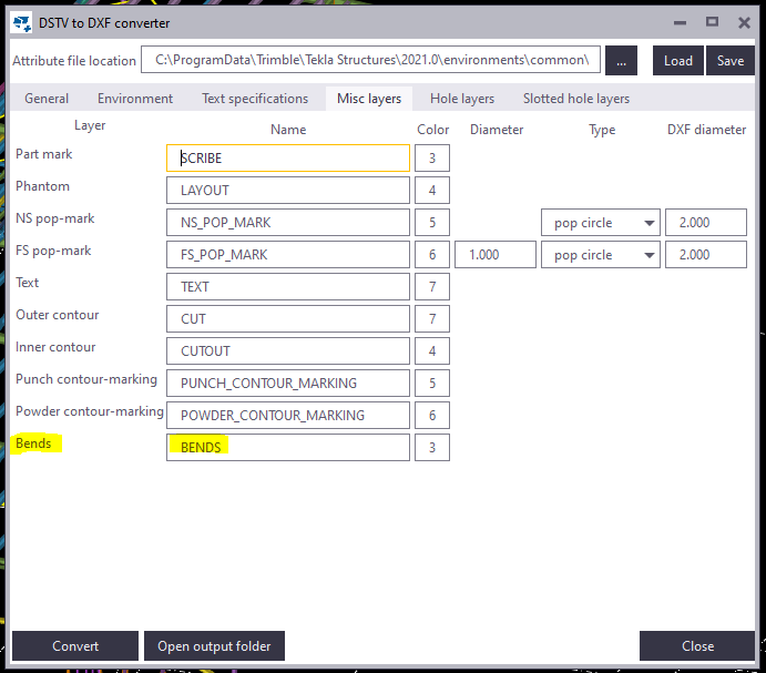
    By default the Tekla Structures can generate drawing with bend lines. But it is not sufficient for the fabricator, until he knows which side to bend the sheet. This can be achived using the plugin “DSTV TO DXF CONVERTER” available on Tekla Warehouse.
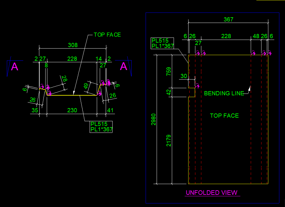
    (Note: Always check if the drawings are created in front view for high quality output.). See below image for clarity

    Snap without bending information on pdf drawings
    Snap with bending information on pdf drawings

    Steps to show bending lines:
    When a DXF file is exported using Tekla it shows reference line. In order to add the bending lines we use the tool “DSTV TO DXF CONVERTER“.In this tool, there is an option to provide a bending line in a different layer on the dxf file. The output dxf files contain information in which direction the sheet has to be bent. This information can be used by the detailer and fabricator for quality output. See below image for clarity

    DSTV TO DXF CONVERTER TOOL
    Snap without Bending information on dxf files
    Snap with Bending information on dxf files

  • Macquarie Park-Hanging Tube Balustrade

    Macquarie Park-Hanging Tube Balustrade

    This is a complicated project, but it came through. Our Scope was Hanging Balustrade around the Ground Floor Lobby. We need to provide those balustrade in numerous panels. This requires much time to complete the model. But we used our modelling techniques to complete it in a much shorter timeline.

    Design wise, We have faced a lot of problems in this job. Especially, The site was existing, so we weren’t able to transport the fabricated panels to the site. Luckily, we found this issue in the initial stages and we informed this issue to the Client. Hopefully, Gonzo Engineering was able to fabricate the panels on site. So that they avoid a lot of Time & Cost.

    This was drawn by Tek1 (Vignesh), if you want shop drawings for a project you are working on, feel free to call Koshy on: (03) 9560 6397.

    Some of the Model Snaps

    Some of the Site Photos after finishing the works

  • Ferrules and bolt length

    Items to take care

    1. Refer Ferrule Catalogue – https://reid.com.au/upload/modules/document_loader/Anchoring_Solutions_Design_Guide_2011.pdf
    2. Check whether ferrule face is flush with concrete or rebated.
    3. Check Thread length in Ferrule
    4. Check total thickness of bolted items including washer.
    5. Make sure that the bolt specified is at least 5 mm less than (WASHER THICKNESS + Plate thicknesses + Rebate in concrete + thread Length)

    Traps

    1. Bolt too long – If thread length in ferrule not taken into consideration
    2. Bolt too short – If washer, Rebate Plate thicknesses not taken into consideration

    Main issue here is the entire length of bolt is decided by the Cut length the modeler provides.

    If proper care is not taken, then there will be a site issue