Category: Precast Detailing Projects

Precast detailing projects show case precast projects detailed by Tek1 Pty Ltd

  • Precast Propping

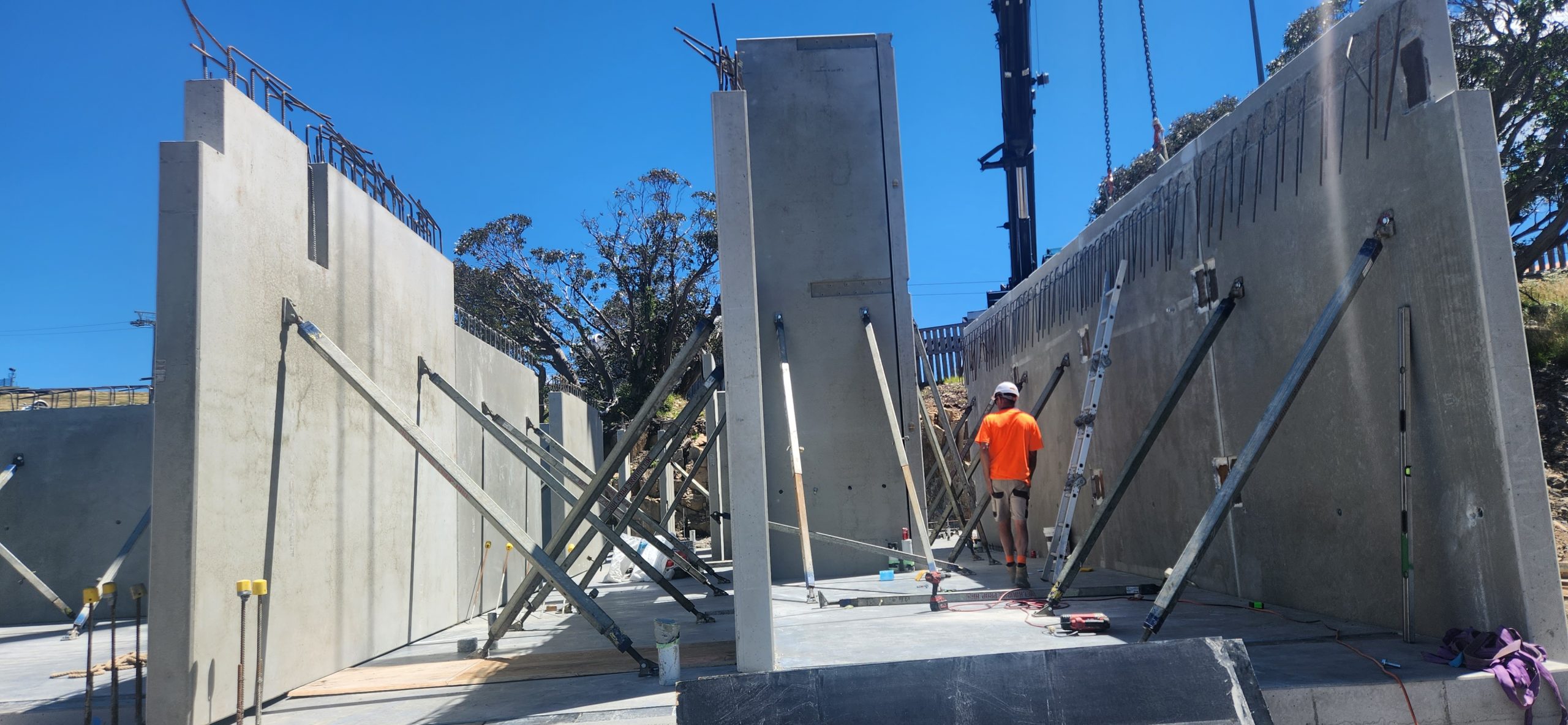
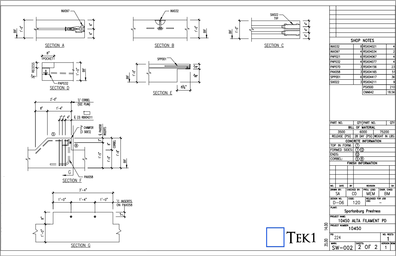
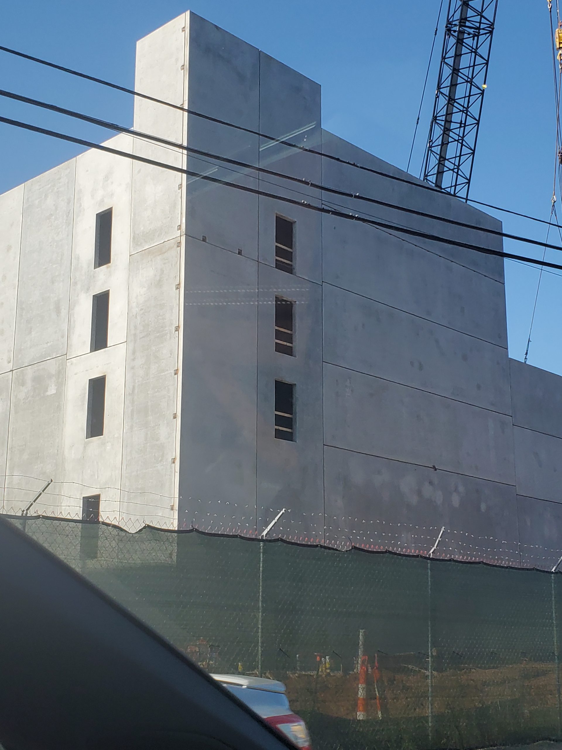
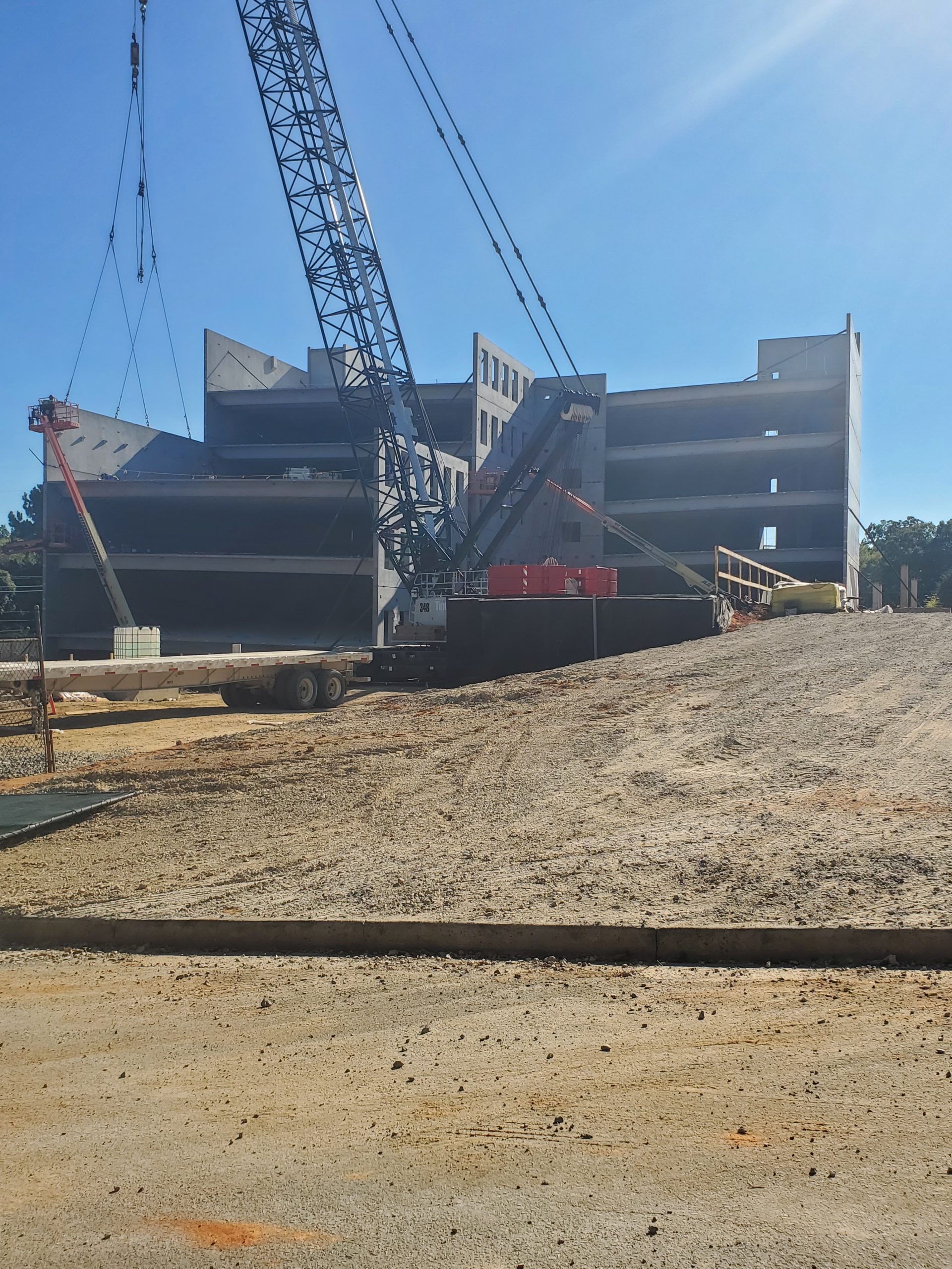
    This is an image showing how precast panels are propped

    Propping parameters

    Usually propped at 2/3rd height.

    No of props usually 2

    if the panels are wide could go to more than 2. But rarely 4.

    For Panels which span 2 floors, There could be 4 props. 2 below the floor above and 2 above. When you have such a case you have to show opening on the slab through which the upper props will pass.

    How long will the props stay in place.

    Usually between 1 to 2 months. It could be longer if the construction pace is slow.

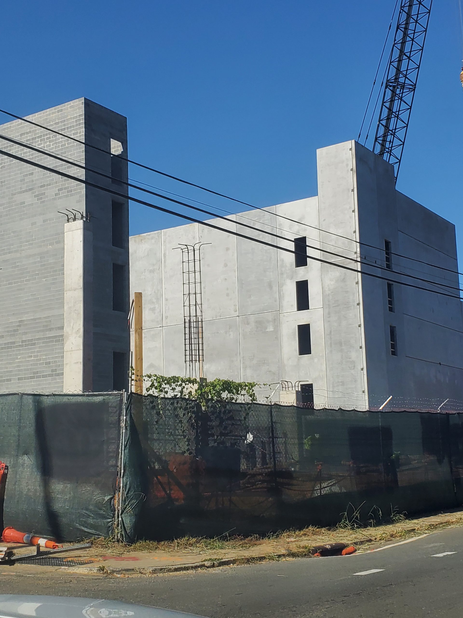
    How many props are usually used in a multi storied construction?

    Depends on construction speed number of panels.

    But the number could be around 200.

    With prop hire rate of around $3 per week, you can see that the cost of propping is not very small.
    When you are estimating for precast, it may be good to consider how many props will be used and what would the cost of propping for a project

    Propping is highly skilled job. Improper prop installation can cause accidents shutting down sites, sending stake holders broke. Not to speak of the harm it does to the site personnel.

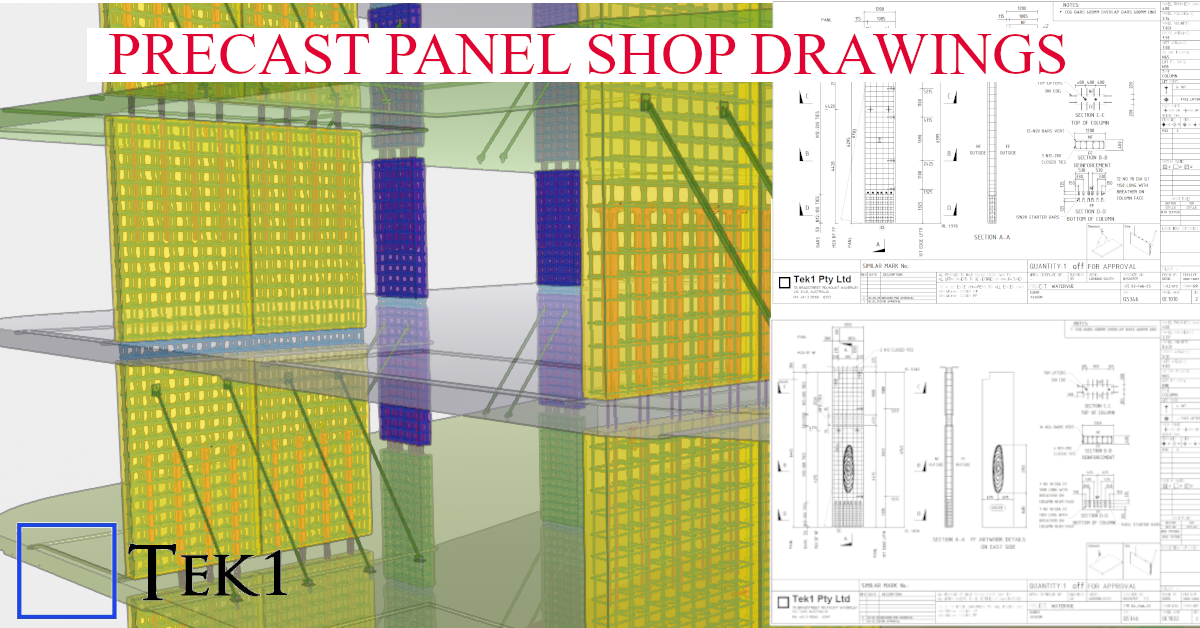
    Who designs the prop.

    Most of the the time props are drafted by the detailer and submitted for approval to the engineer.

    Detailer cannot issue panel or propping drawings unless there is an approval from the engineer. The certification from the engineer is a must. Without that shop drawings cannot go for construciton.

    Without certification, the propping is no go good, illegal and not fit for purpose.

    Insurance companies will not cover if there any issue because of prop failure if the drawings were not certified by a qualified engineer.

  • Adding Ferrule Bolt

    How to create a Ferrule Bolt and Use it.

    Steps Edit Bolt Catalogue. Add the Ferrule bolt in this case we are going start from BOLTFB1640 and create BOLTFB1655 Then we add a bolt Assembly catalog. Again we start from Bolt BOLTFB1640 and create BOLTFB1655 Then we use that in tekla to model the bolt. When you model the bolt make sure 1. No nut is used 2. Washer is on the head side. 3. Cut length is negative of the length you want. This decides the length of the bolt in report. Most important do not ignore — Take report and check.

  • Precast Blade Panels

    Precast Blade Panels

    Project Overview: Reckli Pattern Integration

    At Tek1, we specialize in transforming complex architectural visions into constructible shop drawings. This model snapshot showcases a recent precast project where aesthetic texture meets structural integrity.

    Technical Highlights:

    • Software: Modeled 100% in Tekla Structures for BIM-ready accuracy.
    • Surface Treatment: Seamless integration of Reckli formliner patterns, ensuring the architectural finish aligns perfectly across panel joints.
    • Detailing Depth: Full reinforcement modeling (rebar and mesh), including lifting anchors, grout tubes, and connection hardware.
    • Manufacturer Ready: Our shop drawings are designed to minimize onsite clashes and streamline the casting process at the precast yard.
  • Panel Gaps and Dummy Grooves

    Panel Gaps and Dummy Grooves

    The video explain relationship of panel gaps and dummy grooves.

    As detailer you have RFI what is the panel chamfer and Size of Dummy groove.

    The RFI should be addressed the to precast panel manufacturer and not anyone else.

    If you get this wrong, there will be a fair bit of rework.

    Hence it is important that this is address

    For more videos like this visit.

  • Precast Panels with Tekla Structures

    This is probably first precast project we have attempted with tekla structures as the tool.

    We have done a few with Revit, and lot with Autocad.

    There is raging argument with no one really know (unless one has walked in the weeds) which is a better tool

    I believe no tool as out of the box is really very good.

    Tek1 has been working some using Autocad, develping lot of tools for detailing precast panels.

    Once something is very useful, everyone wants to steal that.

    Code protection is very vital to maintain any sort of edge.

  • TYPES OF MODEL VIEWERS FORMAT , PURPOSE AND ITS BENFITS

    A. IFC Mode

    Industry Foundation Classes (IFC) is an open file format developed by Building Smart Alliance. It is an international data exchange standard for exchanging building information across different software platforms. An IFC Model is just a model of a building or a construction project with all geometric, structural, and semantic information.

    Key Features of IFC Models:

    • Open Standard: IFC is vendor-independent, i.e., any software that supports it can be accessed, without regard for the vendor.
    • Static Data Exchange: It is mostly utilized for data exchange between software tools, data import, and export. For instance, an architect can create a model using Revit and export it as an IFC file, which can then be imported into structural engineering software like Tekla or SAP2000.
    • Limitation of Real-Time Coordination: IFC files are representations of the model at a specific moment. Changes in one application are not duplicated in another except where the file is re-exported and re-imported.
    • Use Cases:
    • Exchange of models between stakeholders with various software.
    • Ensuring interoperability in interdisciplinary projects (e.g., construction, engineering, and architecture).

    Advantages of IFC Models:

    • Encourages collaboration and interoperability in BIM workflows.
    • Reduces errors by making sure all stakeholders are working from the same information.
    • Allows clash detection and coordination between different disciplines.

    B.  Live Link Model Viewer

                      A Live Link Model Viewer is software that enables real-time sharing and visualization of BIM models on various software platforms. Unlike IFC models, which are pre-exported static files, a Live Link Model Viewer enables multiple users to work on the same model at the same time using different software programs. Common examples of Live Link Model Viewers are:

    Revit Live: A cloud-based collaboration platform by Autodesk.

    Trimble Connect: A BIM data management and sharing tool.

    Key Features of Live Link Model Viewers:

    1. Real-Time Collaboration: One software application’s changes are reflected immediately in the model viewer and other linked applications.
    • Dynamic Data Sharing: Unlike static IFC files, Live Link Model Viewers offer dynamic, real-time linking between software applications.
    • Multi-User Collaboration: Multiple stakeholders can view and edit one model at the same time even though they are in different software.
    • Use Cases:
    • Real-time collaboration among architects, engineers, and contractors.
    • Collaborative design review and clash detection.
    • Smooth communication between teams working on different software platforms.

    Advantages of Live Link Model Viewer Benefits:

    • Make collaboration more effective and faster.
    • Eliminate the need for repeated file imports and exports.
    • Enhance accuracy by getting the entire team to work on the current version of the model.

  • ALTA FILAMENT PD (Precast Shop Tickets)

    TYPES OF PRECAST WALL SHOP TICKETS

    A. LITE WALL WITH DOOR OPENING :

    Sheet 1: Panel Profile, Components and their setout Placed in the Bottom In Face (BIF) of the Precast Panel.

    Sheet 2: Components and their setout Placed in the Top In Face (TIF) of the Precast Panel.

    Sheet 3: The Reinforcement Setout on the Precast Panel.

    Sheet 4: Section Detail and Order Form List for the Precast Panel.

    B. LITE WALL :

    Sheet 1: Panel Profile, Reinforcement setout, and the Components Placement on both faces of the Precast Panel.

    Since the reinforcement are not much complicated as like door opening , So they have shown in the Sheet 1 itself.

    Sheet 2: Section Detail and Order Form List for the Precast Panel.

    C. SHEAR WALL :

    Sheet 1: Panel Profile, Reinforcement setout, and the Components Placement on both faces of the Precast Panel.

    Sheet 2: Section Detail and Order Form List for the Precast Panel.

    D. SHEAR WALL WITH WINDOW OPENING :

    Sheet 1: Panel Profile, Reinforcement setout, and the Components Placement on both faces of the Precast Panel.

    Sheet 2: Section Detail and Order Form List for the Precast Panel.

    SITE IMAGES

  • Standard Hooks and Cogs for Precast

    Standard Hooks and Cogs for Precast

    D500 N BAR
    dia d, (mm)
    Pin dia factor f,
    (Pin dia meter dp= fxd
    a
    180 deg hook
    b
    135 deg hook90 cog
    c
    104 for fitments100/105120140/155
    124 for fitments110/115130/145155/170
    164 for fitments / 5 dia 80120/130150/165185/205
    204 for fitments / 5 dia 80140/150200/220220/240
    244 for fitments / 5 dia 80170/180200/240265/290
    28
    32
    36
    40