Cause
* During lifting
* During Transportation
* During Erection
* After erection & slab pouring
Problem
* where the cracking of panel further affected the waterproofing by damaging the internal stud walls of the building.
* Reinforcement getting Weak
* If any interior work will damage due to the weather proof issue.
Remedies
* Get concentrate those location & intimate to reinforce team for additional reinforcement
* Insist to follow the Guidelines from the engineering team
* Insist Factory to concern the reinforcement for the specific openings
* Insist Factory & Erection Crew to Follow the standards & guide line when the lifting from the store, during transport & installation the panel
* During transportation take care all panels sitting on ‘A’ frame to be vertically supported on 2 points & if any additional support should only be for lateral purposes. Insist to follow the transportation guidelines
* The Grouting must be taken care on time for the panel with openings Coordinators to advise if any special cases if needed.
Category: Precast Detailing Projects
Precast detailing projects show case precast projects detailed by Tek1 Pty Ltd.
These projects are in Melbourne, Sydney, WA
We have detailed over 10,0000 panels over 12 years.
-
Cracking of panels at opening Corners
-
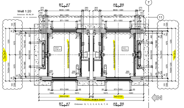
CONSIDERATRIONS-LIFT SHOP DRAWINGS FOR PRECAST
The important things to be considered in lift shop drawings for precast is listed below:
- Core Setout.
- Door Opening.
- Recess at the bottom of lift door.
- Landing Call Buttons penetrations.
- Controller Box Penetrations.
- Service Penetrations and internal platform box.
- Lifting Eye Placements & capacity.
1. CORE SETOUT:
- Lift Core Panels Setout in Concrete plan and structural plan should match with lift core details.
- If any thickness of panels change keep inside dimensions unchanged, because inside dimensions are dictated by lift manufacturer’s drawings. Panels thickness change must affect only the outside dimensions of lift core.
- Propping method – Lift Cores are generally erected first. Higher level slab may not have been poured when lift core goes up. Hence propping of lift core need to have some special attention.
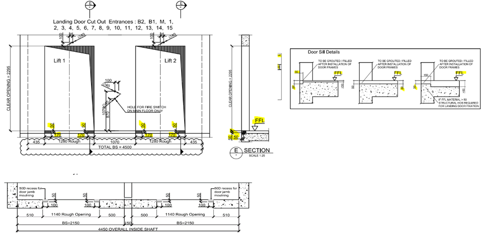
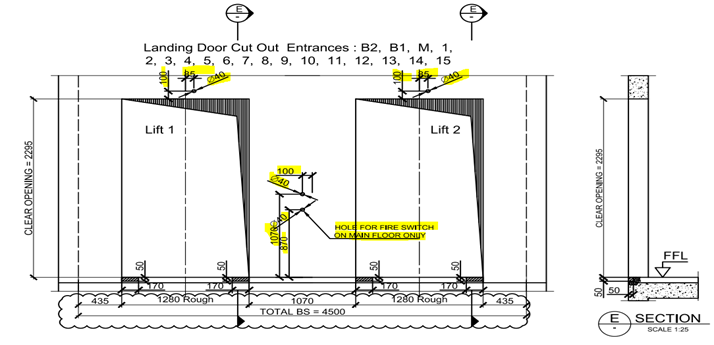
2. DOOR OPENING:
- The door opening width and height of lift in lift drawing should match with architect and structural drawings.
- Make sure that the height of lift door opening in lift drawing are measured from FFL or SSL.
- Minimum Header height should maintained Discuss with interested parities if there any doubt.
- Always consider the RL’s difference between FFL and SSL while the opening height are finalized. FFL and SSL are usually different
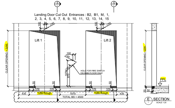
3. RECESS AT THE BOTTOM OF LIFT DOOR:
- The recess at the bottom of lift door (as per door sill detail) is provided for door frame installation. Make sure we take this into consideration
- The door sill details are not same for all projects we need to confirm the depth and width of recess at the bottom of lift door before start the detailing.
- If the door sill height recess is wrongly provided (i.e. Measured from SSL instead of FFL) then there will be a problem in installation of lift door frame.
- The provided recess depth should start from the end of clear opening of lift door.
- Make sure that the Door sill details provided in lift drawings are measured from FFL or SSL.
4. LANDING CALL BUTTONS PENETRATIONS:
- Penetrations for landing call buttons, fire switch and other electrical purpose are to be placed as per lift manufacturer’s drawings.
- First confirm the view direction of lift drawing (viewed from landing i.e. Outside) and precast Setout. It will clear the location of the lift call buttons and other penetrations.
- Ensure the height of penetrations provided in lift drawings are measured from FFL or SSL.
- There will be penetrations of different diameter according to its purpose i.e. call buttons, electrical, fire switch etc. so concentrate more on size and location of penetration while detailing.
- Penetration locations and size may vary according to the respective floor entrances so refer the details from correct floor entrance which is given in lift drawings.
5.CONTROLLER BOX PENETRATIONS:
- Controller box may need a recess or in some cases could be a penetration.
- Ensure the location of the control box from the panel edge, we need to maintain the sufficient gap from the edge of the panel.
- Ensure the sufficient cover from reinforcement with the penetrations
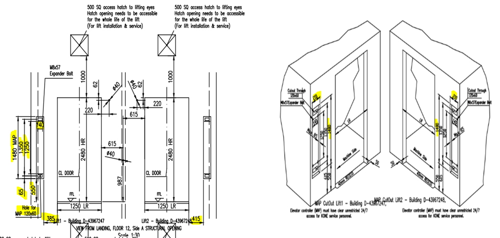
6. SERVICE PENETRATIONS AND INTERNAL PLATFORM BOX:
- Ensure the Hatch opening / exhaust opening need to be accessible for the whole lift for installation & service.
- In some case there will be an internal recess requirement to allow for attaching temporary platforms inside the lift for servicing the lift. Make sure these recesses are same RL and opposite.
7. LIFTING EYE PLACEMENTS & CAPACITY.:
For the whole lift is closed by 2 types of lids One by cast-insitu lid and another by precast lid. If we have the precast lid, we need to consider the following things
- Connection between the vertical precast & lid
- Slope for the water drain
- Finish of the face of the lid
- Lifting Eye & Hooks for the Lift car & accessories fixing
- Ensure the Capacity & size of the Hooks from the lift design.
-
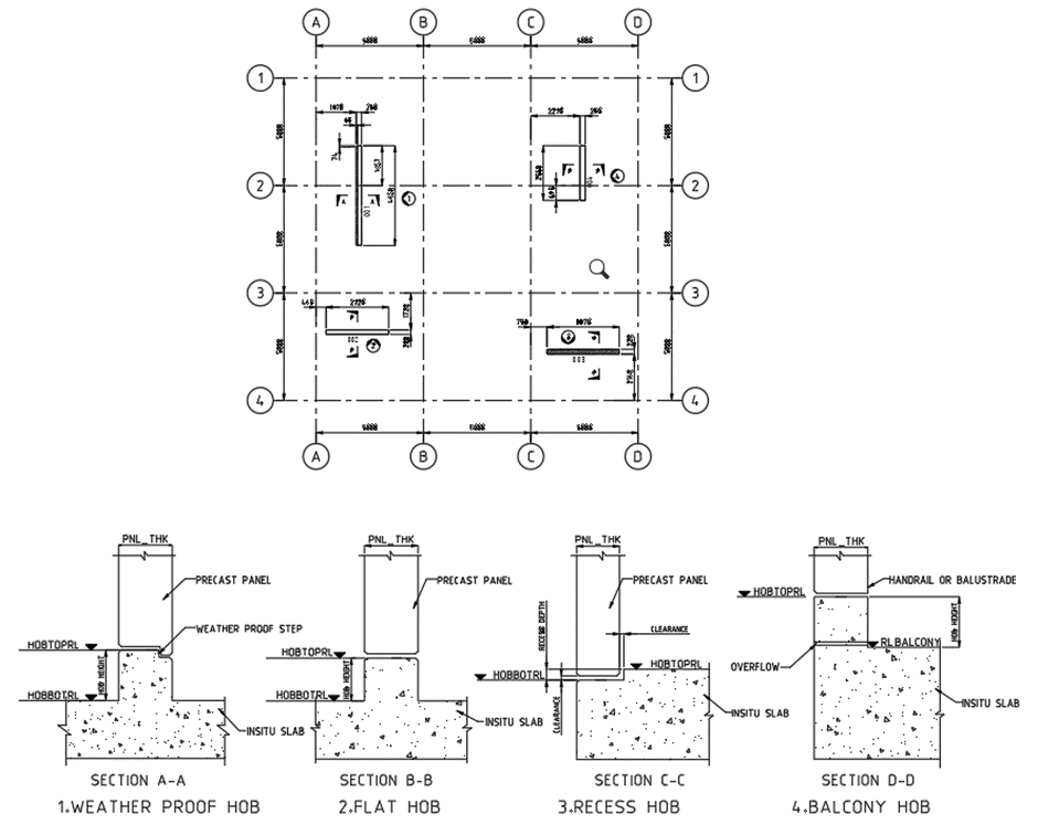
HOB AND ITS TYPES
HOB
Hob is projection or recess on the top of slab, which is made up of concreate or sometimes precast. It will act as a base or foot for the precast panels and balustrade which are to be placed above the actual SSL (Structural surface level) and a locating guide sometimes with weather proof.HOB TYPES
1. Weather proof Or Stepped Hob:
This type of hob has projection from slab SSL, which is used to separate inside (living spaces) and outside (balconies and wet areas) of the building to resist water to enter the building. It has recess at the outside of the building on top of the hob, which means top face has step along the outside of building. Refer Section A-A for weather proof hob.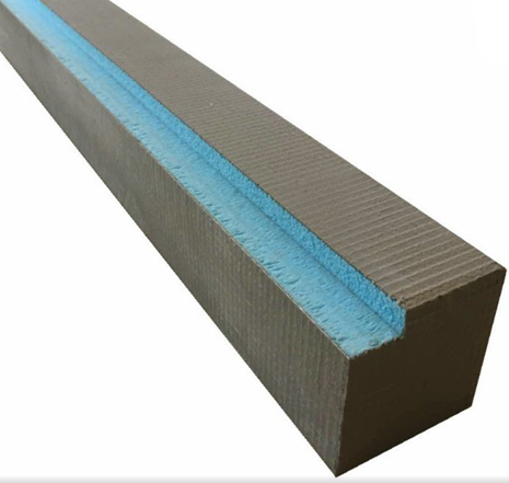
2. Flat hob:
It is also projection type hob, but top face is in full width flat without step. Usually, it will locate between either inside-inside or outside-outside area. Refer Section B-B for flat hob.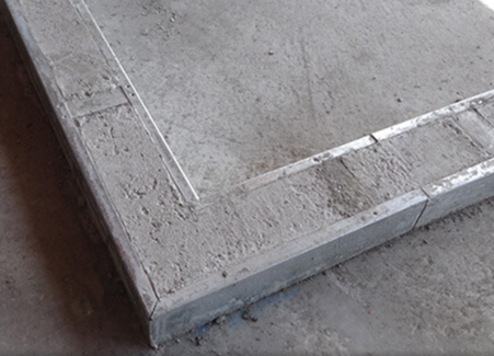
3. Recess hob:
It is further back from SSL or ditch or recess on slab. It will also act as weather proof. This hob needs some gap clearance on the higher side to make easily sit precast on it. Refer Section C-C for recess hob.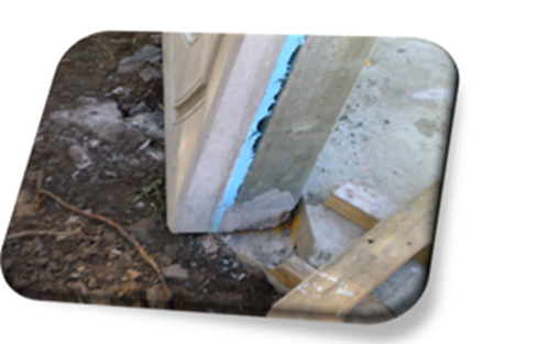
4. Balcony hob:
Balcony hob also be the projection type; it is used to outside of the building in outermost wall to resist spill of water or use as balustrade. Balustrade purpose hob have considerably higher than the all-other hobs. Refer Section D-D Balcony hob.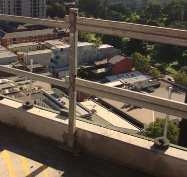
5. Model hob plan drawing:
-
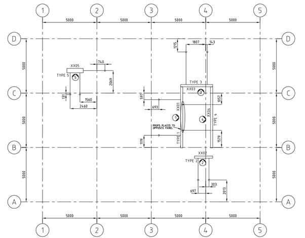
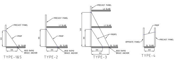
Types of Brace (Prop) Plan
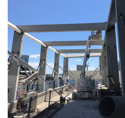
Brace are used for temporarily support precast concrete elements until the permanent fixing are made.
1. Single storey (Drop-in) panel propping
2. Double storey (Spin-up) panel propping
3. Panel higher than double storey propping
4. Panel to panel propping
5. Edge Propping
6. Spandrels propping
1. Single storey panel propping:
Single story panel are normally used 2 props a panel. Some times more than 2 props are used based on panel design.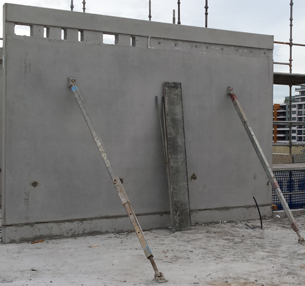
2. Double storey panel propping:
Double story panel are normally 2 props placed 200mm below the underside of slab. Some times more than 2 props are used based on panel design.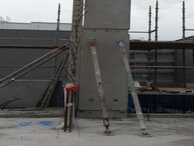
3. Panel higher than double storey panel propping:
This type of panel needs two level of propping. Two props on the below level and two props on the above level. If there is a slab in above level the propping system will pass through the below level slab by providing a pocket on the slab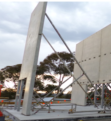
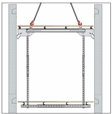
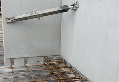
4. Panel to panel propping:
Provide ferrule in the opposite panel Or Adjacent panel for propping. Especially this kind of propping system are applicable for lift and stair core area, where there will be no slab to support the prop.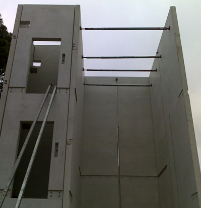
5. Edge Propping:
These types of propping are used for column and some panel having cantilever. Provide ferrule in the edge of the panel.
6. Spandrels propping:
These types of propping are used for spandrels. Provide ferrule at the top of panel. Where the ferrule will be connected with the member which hold the propping system.
Model brace plan drawing: