Category: Steel Detailing Blog

This page show cases some of the Steel Detailing projectgs completed in Melbourne, Sydney, WA, Brisbane Tek1 has completed

  • A quick study on Chemical anchors

    A quick study on Chemical anchors and things to note while modeling members with chemical anchors.

    Chemical anchoring is a technique for fastening to concrete and similar substrates that provides more flexibility than mechanical anchoring. The chemical or the resins will create a strong bonding between the anchors and the concrete material. When an anchor is installed into concrete, there is an area surrounding the anchor called a cone of influence in which the anchor is affecting and it is affected by.

    We shall see two key factors while modelling in Tekla structure based on the cone of influence.
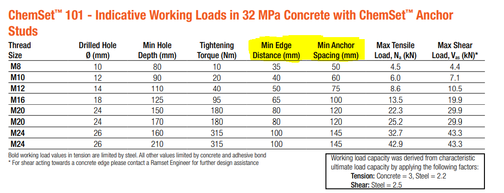
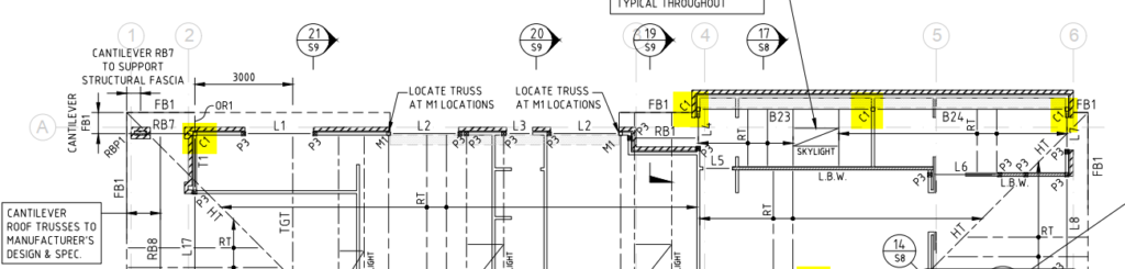
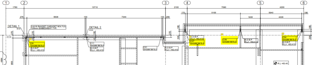
    Two key points to note while modeling the members with chemset anchors are:
    The Edge distance:
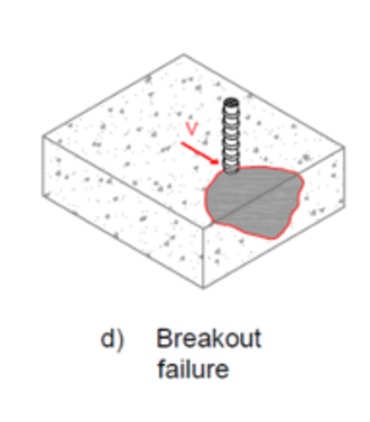
    When an anchor is placed closely to the edge of the concrete, the anchor cone gets influenced and causes reduction in anchor’s tension and shear capacities. Placing chemset anchors close to the edge of the concrete causes Edge distance failure. Refer below snip for clarity.

    In order to avoid the edge distance failure we must follow the necessary Min. Edge Distance value nominated for the anchor used. Here we have highlighted one such example in IMAGE – 1.

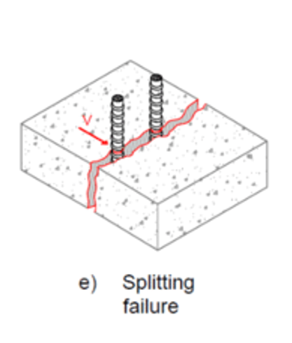
    The Minimum anchor spacing:
    When two anchors are spaced too closely to one another, the anchor’s cone of influence reduces or becomes interfered, with this inturn reduces the anchor’s tension and shear capacities. As embedment increases, the anchor’s cone of influence increases and there will be an increase in tension and shear capacities. Refer below snip for clarity.

    However, embedding an anchor too close to the opposite face of the concrete can lead to spalling damage.

    In order to avoid the edge distance failure we must follow the necessary Min. Anchor Spacing value nominated for the anchor used. Here we have highlighted one such example in IMAGE – 1.

    In summary : If we could follow the above two key points, we could avoid concrete failure on site at modelling stage (beginning) which could save cost and time.

    Blog by Bharath – Tek1.
    Visit www.tek1.com.au for further enquiries.

  • Warringah road – wakehurst bridge

    Warringah road – wakehurst bridge

    Wake-Hurst-with cladding
    Wake-Hurst-without cladding
  • ROBINSON’S BRIDGE WALKWAY STRUCTURE WITH CLADDING

    ROBINSON’S BRIDGE WALKWAY STRUCTURE WITH CLADDING

    TEK1 Successfully done this Robinson’s bridge walkway by one time detailing without any hitch

    ISOMETRIC VIEW OF ROBINSON BRIDGE WALKWAY STRUCTURE WITHOUT CLADDING
    CROSS SECTION VIEW OF ROBINSON BRIDGE WALKWAY STRUCTURE WITHOUT CLADDING
    ISOMETRIC VIEW OF ROBINSON BRIDGE WALKWAY STRUCTURE WITH CLADDING
    VIEW OF ROBINSON BRIDGE WALKWAY STRUCTURE WITH CLADDING

  • BURDELL STATE SCHOOL_CAM_BUILDING

    BURDELL STATE SCHOOL_CAM_BUILDING

    We have done steel detailing for the building called CAM inside the burdell school within a short period of time without any issue.

  • MT ARTHUR COAL TOWER 24m HEIGHT

    MT ARTHUR COAL TOWER 24m HEIGHT

    TEK1 Successfully done this MT.ARTHUR COAL TOWER by one time detailing without any hitch
  • Why Assembly Label cannot be the same in Shop Drawings and Structural Engineer’s document?

    Client query: Some of our clients ask us why the Labels for assemblies varies in our shop drawings from the labels mentioned in the Structural Engineer’s documents.

    This Blog explains why this can’t be done.

    Comparision with Structural documents:

    Normally, In Structural Engineer’s documents the same label will be given to the members of same profile used in different instances irrespective of their other properties such as change in geometry, connection members welded to the assembly, etc.,

    For Example: In below image, the highlighted column C1 – SHS 89*6 is used in multiple instances.

    Snap From Structural engineer document

    Working with Tekla Structure:

    In general, This method cannot be followed while detailing because each member (even if the profile is same) will have it’s own shop drawing depending upon the change in any of its properties such as geometry, material, finish, connection members welded to the assembly & so on.

    Refer below snap for clarity.

    Snap From Tek-1 GA Drawing

    In summary, although we have used the same profile for the column C1 as mentioned in structural documents, due to the change in connecting members welded to the column and change in geometry we have provided different labels in the GA drawings.