Category: Steel Detailing Blog

This page show cases some of the Steel Detailing projectgs completed in Melbourne, Sydney, WA, Brisbane Tek1 has completed

  • Trimble Connect – The powerful collaboration [Ep-1]

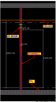
    Trimble Connect is a powerful collaboration tool for Architecture, Engineering and Construction (AEC) Professionals including the Architects, Engineers, Detailers, Sub contractores, General Contractors and Project owners. This tool helps in collaborating the models among all the members of the project. This tool makes the project information accessible, transparent and traceable and to help users to build better.

    It keeps everyone in the hierarchy of the project updated about the progress and the next course of action. Trimble Connect accessibility via the web, desktop and mobile devices makes it userfriendly to share, view and access construction project data anywhere and anytime. Some of its main features include an activity feed, align models, export reports, create a project, coment on to-dos, file explorer, model object filtering and clash detection.

    TRIMBLE CONNECT FEATURES :

    • 3D markup

    • Align models

    • Activity Feed

    • Comment on to-dos

    • Combine and view selected models

    • Change color of some objects

    • Control visibility of entire model

    • Create a project

    • Define custom reports

    • Create and manage folders

    • Create and manage releases

    • Exchange to-dos using BCF 1.0

    • Export reports

    • File Explorer

    • Manage permissions and notifications

    • Model object filterin

    • Manage users and groups

    • Save views

    • Run clash checking

    • View/comment clashes

    • Temporary local offline storage

    Let us see how we are going to collaborate using Trimble Connect in upcoming blogs. Follow the blog updates regularly for more Trimble Connect videos.

  • Selection method for Reports Creation in Tekla

    While creating reports in Tekla Always ensure that selection men must be in objects selection. See below snaps

    OBJECTS SELECTION 
    COMPONENT SELECTION

    Above snaps clearly states reports must be taken while the members selected in objects selection option is turned on. Otherwise the report quantity will be less than the actual quantity.


  • HAVE YOU TRIED IN AUTO CAD #2: CREATING CUSTOMIZED NEW RIBBON

    We do use a set of commands frequently, in those case we used to switch between using mouse and keyboard. if we try to click on the icons on the default ribbon we need to search them every time.

    Auto cad has provided with an awesome facility that we could customize a ribbon in our work space, while customizing a ribbon we could just select the tools which we need and we could have a personal ribbon.

    Procedure:

    1. we could use the CUI command to enter into the “Customized user interface” dialog box.
    2. In customize tab, we need to create a ribbon. So, select the + symbol near the ribbon. Here we have two options tabs and panels.
      Tabs: it is the header of the ribbon and they can have number of panels into them.
      Panel: They were the header of a group which has number of tools.
    3. We first need to create a panel by just right clicking the name panels then new panels and name your custom panel.
    4. In the list of commands list which is available below select the command and drag and drop it into the panel rows.
    5. We could create Tabs by right click and name it.
    6. Once we have created all the panels we need to drag and drop them into the tab we have created.
    7. We could assign this ribbon to work space to have our own customized sets of tools in a single ribbon.
    8. we could use the combinations of existing tabs in our ribbon as well.

    We could also customize our work space.

  • Can you spot the Problem#9


    ARCH PLAN & RCP

    Can you find any discrepancy from the above Structural and Arch design Snaps.


    Hope you got it.

    Profile of beam B1 is150UC30 from the structural drawing.

    The beam comes below ceiling. It would not be an issue if the stud wall accommodates the beam. But, the thickness of the stud wall is only 92mm and the beam is 150UC30. The beam will be accommodated neither within the ceiling nor the stud wall.

    So, we have changed the Beam B1 profile from 150UC30 to PFC200*75 to accommodate the member within the 92mm thick stud wall and asked for confirmation.

    We attached model snap for better understanding to the Client.

    MODEL ELEVATION  SNAP

    Client understood the issue we encountered and agreed to change the profile of the Beam B1.

  • NCDXF Files and & CSK Bolt Holes (in Tamil)

    NCDXF Files and & CSK Bolt Holes (in Tamil) from Tek1 on Vimeo.


    Hi team, please review the video for CSK bolt holes and NCDXF Files – language is Tamil.

  • GRASSHOPPER- THE VISUAL PROGRAMMING LINK FOR TEKLA

    Ever wondered how to automate the processes in modeling of steel structures, increase efficiency and accuracy. Grasshopper has got all the answers. Grasshopper is a visual programming interface like the Dynamo we saw in the previous blogs. It is built in within the 3D modeling software called Rhino. Tekla has released a link which enables algorithmic modeling for Tekla Structures using Rhino/Grasshopper. Even the toughest and tiresome models can be easily created using the Grasshopper-Tekla Live Link provided you have a strong visualization capacity and good understanding of the underlying geometry.

    We have tried using it for our jobs and it provides great flexibility to alter the parameters. One of the job we used for is creating a Spiral stair and the process was pretty easy and we got accurate results. Another challenging  job we experimented was the outer framing for cladding panels, along the sides of a bridge which had a tricky geometry. Have a look at these in the following video.

  • ISSUES OF EXPORTING DSTV TO DXF WITH CSK BOLTS IN TEKLA MODEL

    Wherever Countersunk bolts are provided in a model, it is advised not to send NC DXF files to the client for the corresponding plate/shaft. This is because the hole dia in the generated NC & DXF file is not the actual bolt dia but it is the dia of the countersunk head. Therefore, the hole dia in the plate/shaft is much higher than the actual value. Hence, it is advised not to send NC DXF files for plates/shafts which has countersunk holes.

    But, when the client demands for NC DXF files even for plate/shaft with CSK bolts, the generated NC DXF files must be manually edited such that the CSK hole dia in the NC DXF files is bolt dia + 2mm(Tolerance).

    Also the tolerance for CSK bolts must be 2mm everywhere irrespective of the members the bolt is connecting i.e, whether it is steel to steel connection or steel to concrete connection the tolerance for CSK bolts must be 2mm.


    By Ramakrishnan.L

    TEK1

  • DYNAMO: MODELING COMPLEX STRUCTURES

    When it comes to 3D modeling, there always exists limitations with conventional modeling software while working with complex structures. In business, it is very important that each and every need of the customer must be fulfilled without compromise. With these things in mind we started experimenting various ways to model complex structures. Dynamo came into help here. The main advantage of using Dynamo is its accuracy and speed.

    We have done a aesthetic facade for an atrium using Rectangular hollow steel section which comprise of a Sine wave geometry in its elevation. Without the need of creating each and every piece individually we created a script which automatically generated the facade with the required profile. The final output was really accurate which may be limited when doing it manually. The size and shape of the overall model can also be adjusted easily to our requirements by using Dynamo.

    If you want us to model any challenging structure like this, please do contact us.


  • DYNAMO: THE GAME CHANGER

    Automation is the process of making a task automatic, an essential requirement for all business processes to achieve accuracy in repetitive tasks, where humans or manual tasks are prone to error. One of the most powerful automation package of recent times in the construction industry is the Autodesk’s Dynamo. It is an open-source visual programming tool which works with Revit and other Autodesk products but could also be integrated with non-Autodesk programs using Standalone releases like Dynamo Studio, Dynamo Sandbox, and Project refinery.

    Unlike other Application Programming Interfaces which are used by well-grounded programmers, people with minimal coding knowledge can create custom scripts using the Dynamo to access the Revit interface. It runs on the background of Design script and Python. With Dynamo, the opportunities are endless and many time consuming tasks in various disciplines such as design, detailing, modeling, analysis, documentation can be automated.

    We use Dynamo to find potential solutions to problems we face day-to-day. One such problem was the unavailability of 3D grids in Revit. Moreover even when exporting a Revit model to CAD .dwg format, the grids failed to show up but they are available with Ifc exports. We developed a simple script to solve this issue using Dynamo.

    The workflow between Revit and Dynamo is shown here.

    The above snip shows the sequence of nodes in the dynamo workspace which were used to create Grids in 3D view.

    We found it quite interesting when we started digging to explore the capabilities of Dynamo to help us with our jobs. Learn more about Dynamo: https://dynamobim.org/

    If you have any questions or opinions about this post please do comment below.

    Written by Madhumitha Balaji