Category: Steel Detailing Blog

This page show cases some of the Steel Detailing projectgs completed in Melbourne, Sydney, WA, Brisbane Tek1 has completed

  • HAVE YOU TRIED IN AUTOCADD#3: QUICK SELECT (QSELECT)

    Shortcut command: QSELECT (right click on the work area to get this command)

    When you need to select a specific element in an AutoCADD project, like for example some construction lines, you could select them either one by one or by using select similar when you need to select some specific items for which you know the properties we can use the quick select tool. This is very similar to the selection filter in Tekla Structures and in Revit.

    Using Quick Select or QSELECT, you could select the line of specific length or a specific colour. You could also use the tool to select elements specifically needed to work on in any area.


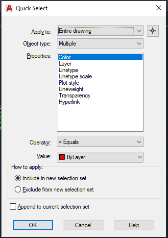
    Here is the list of options:

    1. Apply to: This restricts your selection to the required area or to the entire model as required.
    2. Object type: Select the object which needed. For example, if we need to select all the lines which has length less than 1m then you need to set the object type option as line.
    3. Properties: in this category we can specify the property of the object we need to select. In case of above example it would be the length.
    4. Operator: it is the usual comparison operators. for this case we could give lesser than.
    5. Value: According to the property we select we need to specify the value. in the above case we could specify 1000mm.
    6. How to apply: This is part is more interesting and very useful as well. If we use the radio button “Include in new selection set” the elements which passes the condition would be selected, if we use “Exclude from the new selection set” the case will be vice versa. ie. all the elements which does not satisfy the condition will be selected.

    Please find a short video on demo of the content below.

  • Trimble Connect- GA Drawing 3D-Export [Ep-6]

    GA Drawings overlay on IFC Model

    Ever wondered about how easy and accurate it would be to study a GA drawing when it is overlayed on the IFC Model? Well, Trimble Connect gives you a way to do so. The GA drawings are exported along with the 3D co-ordinates as dwg files in Tekla Structures. This process is easy and we have to make sure to activate few options in Advanced Options and in Export Drawings dialog box.

    • In Advanced Options dialog box, Select Export and look for the option XS_DWG_EXPORT_3D_MODEL_COORDINATES and change the value for it as TRUE.
    • Once this value is made true then we can proceed with the regular method of creating the GA Drawings and then export it.
    • When exporting the GA drawing, we have to make sure that the Model Space Co-ordinate value is made Model instead of Local.
    • If the model space co-ordinate is kept as local then the dwg file will take the local co-ordinate values as in the drawing created and the 2D dwg files are exported.
    • If the model space co-ordinate is kept as model then the dwg file will take the Tekla model co-ordinate values and the 3D dwg files of the GA drawings are exported.

    To have a more clear idea of how this option works refer to the video attachment.

  • Can you spot the problem#10

    Initial Structural design
    Arch design

    Did you find anything missing from the above Design?

    The Roof has slopes. But there is no consideration for gutter provision and its support.

    We figure out this issue and raise RFI against this issue.

    RFI regarding the missing consideration of Gutter and its fixing

    Client approves to make changes in the design and send us back. See below revised design

    Revised Structural Design
  • A Beginners guide to APIs

    Is programming knowledge necessary only for a Software developer? You will find an answer for this question in this blog. With automation ruling the world, it is important for every business to adopt it into their workflows to stay competitive.People may encounter lots of issues and errors in day to day work which may affect the efficiency and productivity. Laborious tasks can be automated using simple tools which can enhance productivity. This is where API comes into action.

    An API (Application Programming Interface) is a set of tools, protocols and methods offered by companies for their commercial software. Some of those companies offering API are Google, Mircrosoft, Autodesk, Tekla and the list goes on. Everyone who are using their software may want to have a customized tool to suit their special requirements. Hence for this purpose the application developers expose some of their core codes for their customers. Now the customers could query, retrive data, set values and do much more.

    How API works.

    A Civil engineer may be working with many software and when he has some knowledge on programming he could develop solutions using these API without hiring a software engineer and explaining all sorts of things to him. When he himself gets to explore the API, various possibilities will come into light and he could develop more productive tools for his business.

    All one needs to get started with API is some basic understanding of the high school computer science concepts on C or C++. Even though they are low level programming language unlike JAVA and C# which is required to work with API the concepts remains the same. JAVA has a lot of scope than C# which is mainly used to develop Microsoft Windows applications. But the selection of which one to learn depends entirely on what your requirement is as each API has been built on its own language. Once you get a fair bit on the language next important thing is the documentation of the API.

    This documentation is available in the websites of the software. It serves as a guide which explains the entire hierarchy of the software, data types, classes, methods etc. One needs to dig into this at the very beginning before accessing the API. Now you could start your coding after acquiring the basic knowledge on these things. Keep in mind that lots of trial and errors will only lead to success for a beginner. You should be continuously learning from the errors arising in the code and working on it further.

    Hope this blog has provided an insight on how important programming could be for people in industries other than IT. Well then get started to learn coding and explore new heights in your business and work.

  • CHECK TRANSPORTATION FEASIBILITY WHILE WORKING IN AN EXISTING STRUCTURE

    The conventional maximum transportation size for an assembly is 12m x 2.5m x 2.5m. This value is not applicable for all the conditions.

    TEK1 executed an alteration work inside Canberra airport. Everything that enters an airport must go through the checking / screening area. As per design, the size of assemblies were more than 9m & we were not sure whether these assemblies could be transported into the Airport. So, TEK1 raised a query regarding this. The client agreed to reduce the size of transported assemblies.

    Lesson: Whenever a work is carried out inside an existing building, consideration must be given for taking in the assemblies i.e. door/entrance size is mandatory. Since a completed airport terminal is a closed roof structure, cranes cannot be used for erection. Here the erection is done with the help of genie lifts. Weight carrying capacity of the erection machinery must also be taken into consideration.

    See below design snap & TEK1 proposal markup for splice location.

    ABOVE SNAP TAKEN FROM STRUCT DESIGN. SHOWN ASSEMBLY SPLICE LOCATION AS 9300 mm.

    PLEASE REFER BELOW SNAP WHICH SHOWS PROPOSAL MADE FROM TEK1 & THAT WAS APPROVED BY STRUCT ENGINEER.

  • Trimble Connect- Creating ToDos [Ep-5]

    Raising RFIs in the project has been made much easier by the use of ToDos. Creating a ToDo and assigning it to a particular person in the project and following it up till the closure of the RFI  is possible now which will greatly help in tracking the project queries and taking quick actions. A video on how the ToDo is created has been uploaded.

  • Trimble Connect- Markups and Views Creation [Ep-4]

    Markups can be done directly on the models and views based on the markups are created. The created views containing the markups can be later reviewed by any user in the project. The video on how to do markups and create views has been attached for reference.

  • Trimble Connect- Viewing and Hiding Objects [Ep-3]

    Viewing of Objects by overlaying the drawings over the IFC model has been an added advantage. The GA Drawings which are exported to Trimble Connect by taking model co-ordinates as origin will be easier to overlay on the IFC Models. It can be either hidden or viewed by selecting the required view. A video on how to view and hide the objects and drawings has been uploaded.


  • Trimble Connect-Connecting with Clients [Ep-2]

    Once a trimble connect invite for a particular project has been received, kindly follow the below steps,

    • Click on the view project option in the invite mail.

    • If the mail id to which the invite has been sent is not signed up in Trimble Connect, then kindly create an account in Trimble Connect using the same and then try logging in to view the project.

    • Once you sign in using your account and try viewing the project, you might have this screen pop up.

    • You can continue as a free user as long as Trimble Connect keeps this option active.
    • Once this personal user access gets disabled you can request to share a license from us.

    Sharing license with external users makes it easier to collaborate the models with the clients. The process about how to accept the external user license has been shown in the video.