Here we are going to discuss about the member placement issue.
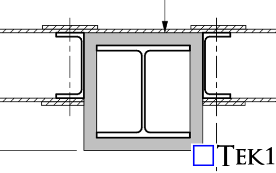
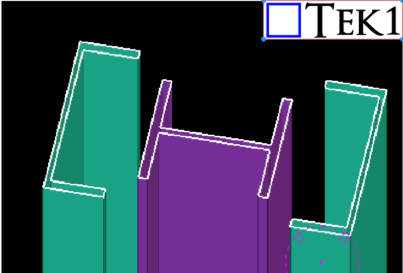
The design specified two PFCs on both sides of a column.Column was surrounded by fireproofing sheets. However, the PFC flanges clashed with the fireproofing sheets, making installation difficult. Additionally, the bolts connecting the PFCs would interfere with the fireproofing.
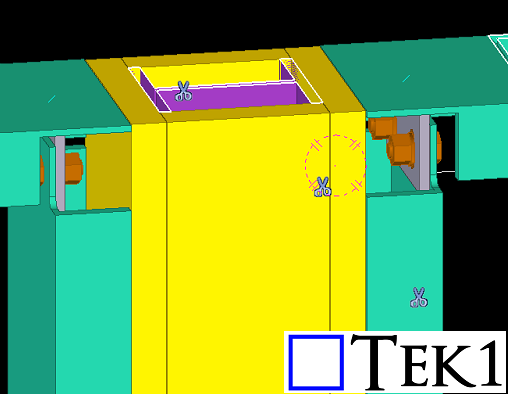
To resolve this, TEK1 planned a simple yet effective adjustment—changing the orientation of the PFCs. This allowed for seamless fireproofing installation without compromising the structural integrity.
If we have followed the design , then the erection team will have difficulties to provide the fireproofing sheets.By identifying and addressing potential clashes early in the detailing process, TEK1 saved significant time and costs for the client, ensuring a smooth execution on-site.
Stay with TEK1 for more updates on steel detailing challenges and solutions in our upcoming blogs.
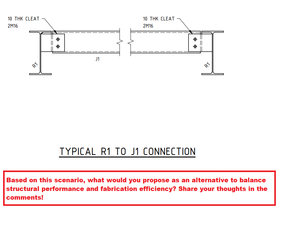
Based on this scenario, what would you propose as an alternative to balance structural performance and fabrication efficiency? Share your thoughts in the comments!
Introduction
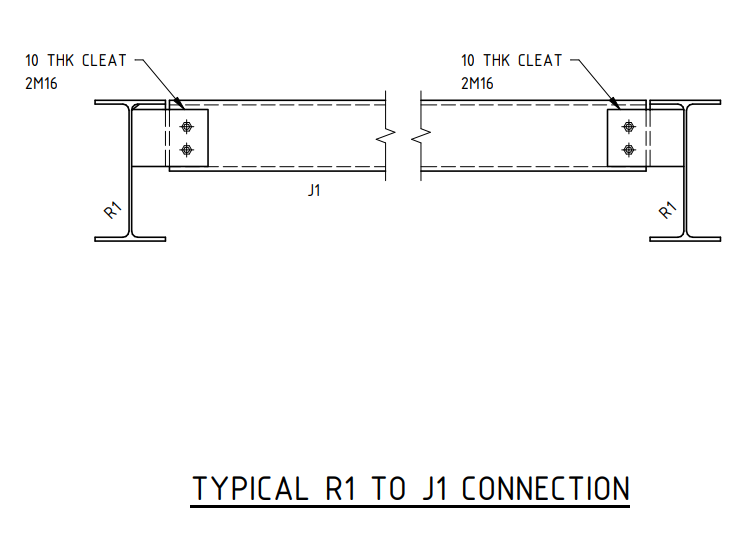
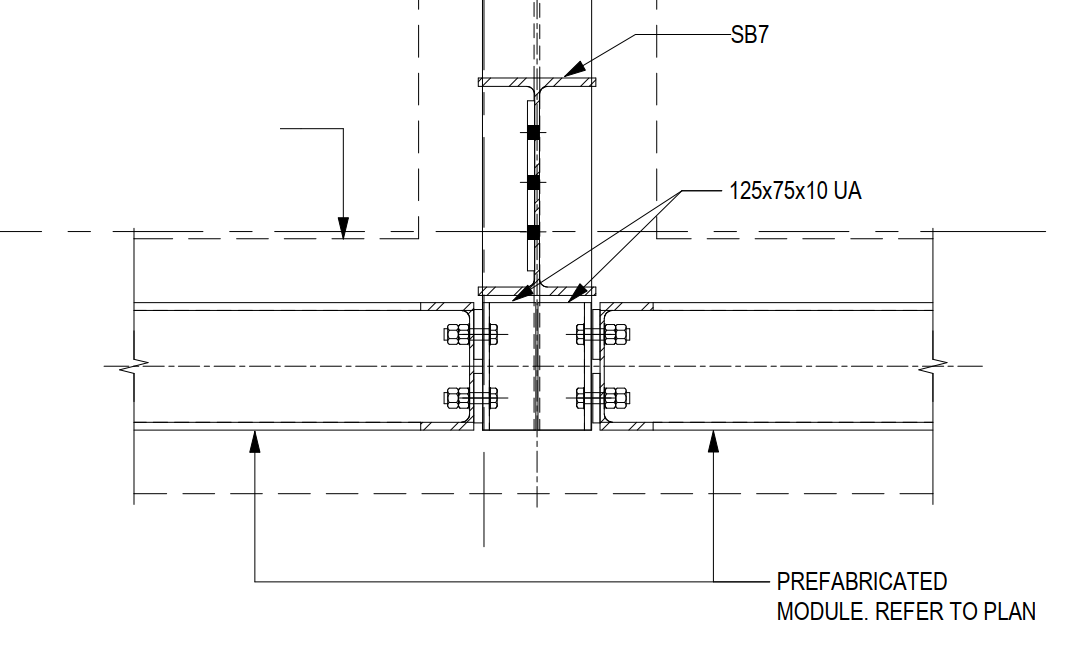
Shear connections play a crucial role in structural steelwork, ensuring the stability and strength of a framework. One common method is the extended shear plate connection, as seen in the R1 to J1 connection detail. However, this method introduces bolt eccentricity, which could impact the overall efficiency of the joint.
The Challenge
In the given design, the PFC (Parallel Flange Channel) shear connection is detailed using an extended shear plate. While this is a standard approach, it inherently results in increased eccentricity due to the offset load transfer through the bolts. This can lead to additional bending moments in the connection, requiring careful consideration in the design phase.
Possible Solution
A potential improvement is to introduce a cope in the PFC section and utilize a simple shear connection instead. This modification would:
Reduce bolt eccentricity
Simplify force transfer
Enhance structural performance
However, this approach was not accepted by the client due to fabrication ease considerations.
Key Learning for Junior Engineers
This case highlights a key engineering principle: design optimization vs. fabrication practicality. While structural efficiency is paramount, practical considerations such as ease of fabrication, cost, and site constraints often dictate final design choices.
TEK1 is currently engaged in steel detailing for the Sydney Metro project, working with a reputed organization in Australia. During the detailing process, we have encountered several design challenges. Here, we will share one such issue and how we resolved it.
The Issue
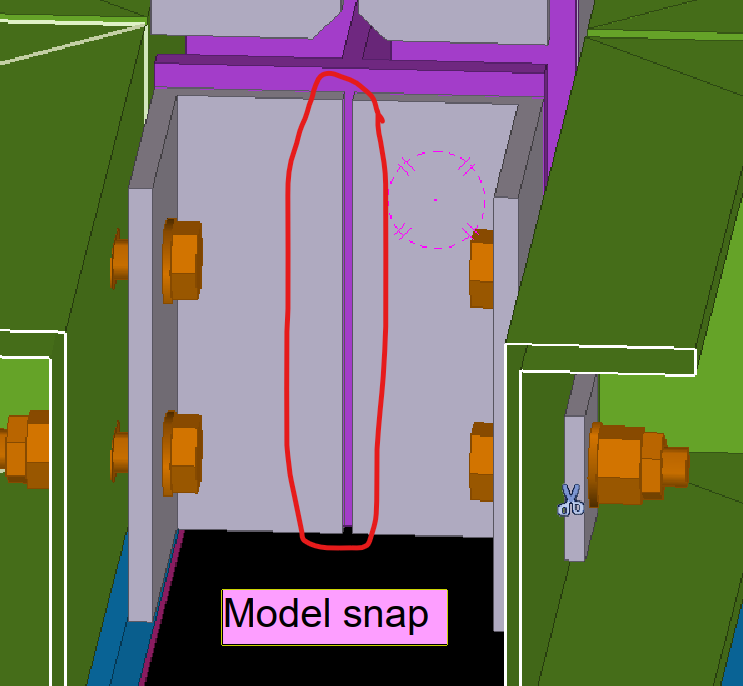
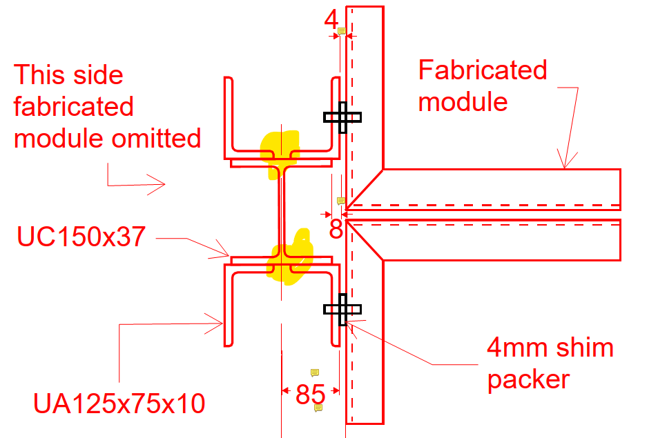
A design required two unequal angles welded to a small hanger with 10mm packer plates. This left insufficient weld space, making fabrication tough.
Recognizing this issue early, we raised a query with the concerned team. Our initial proposal was to cut both angles to create the required weld space.
After reviewing our concern, the team suggested an alternative solution that involved reducing the packer plate thickness from 10mm to 4mm. This adjustment allowed for a 6mm weld clearance on both sides without significantly affecting the design.
If this issue had gone unnoticed and we had followed the original design, it would have caused complications for both the fabricator and the designer. By identifying the problem early and addressing it proactively, we saved time and costs for the client.
Stay Tuned for More Insights
This is just one example of how TEK1 ensures seamless steel detailing by resolving design issues efficiently. Stay with TEK1 for more updates on steel detailing challenges and solutions in our upcoming blogs.
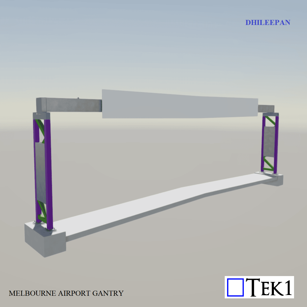
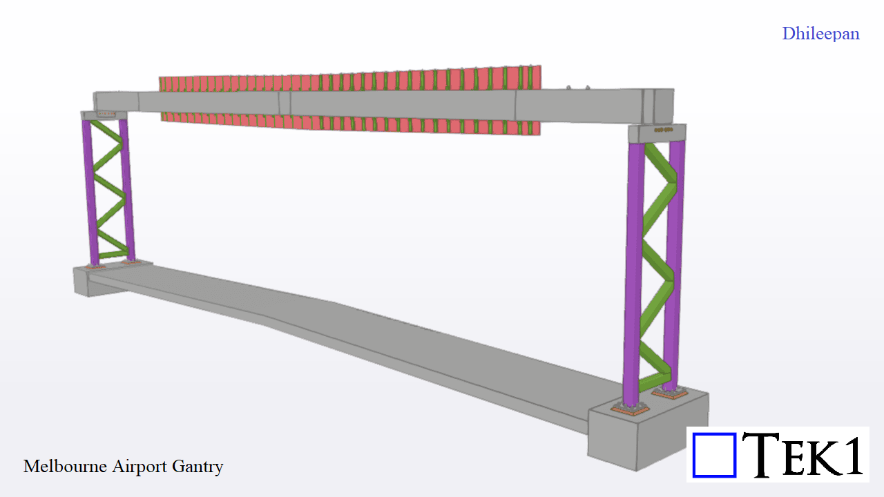
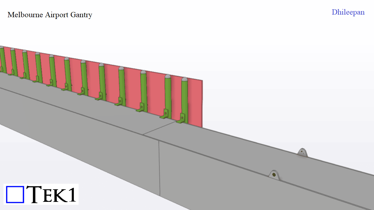
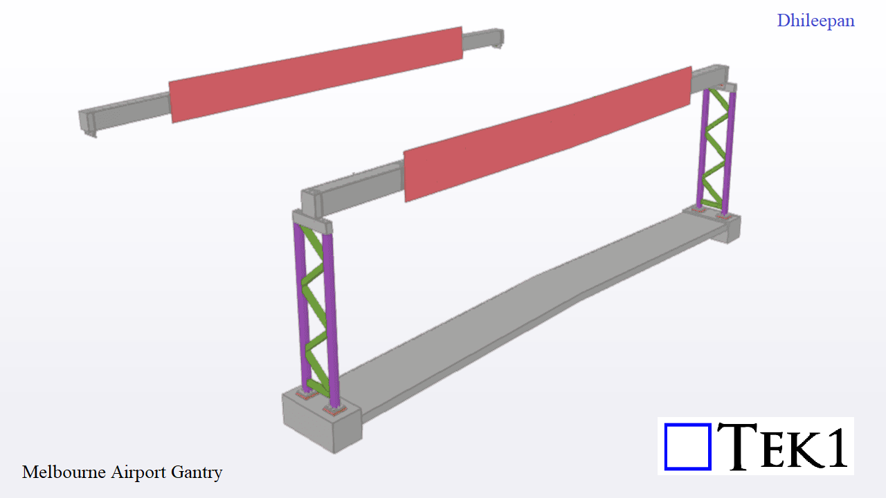
At Melbourne Airport, a gantry supporting a signboard spans 26 meters between laced columns without intermediate supports. The box gantry alone weighs 8 tonne. Since the gantry would bend because of to its self weight, pre-camber of 170mm was provided at the middle.
For accurate representation, two models were created: one with pre-camber for assembly drawings and another without for general arrangement (GA) drawings. This approach ensures clarity in fabrication and erection, maintaining structural integrity while achieving the desired final alignment.
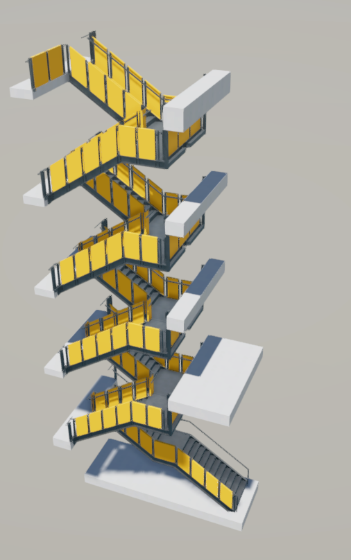
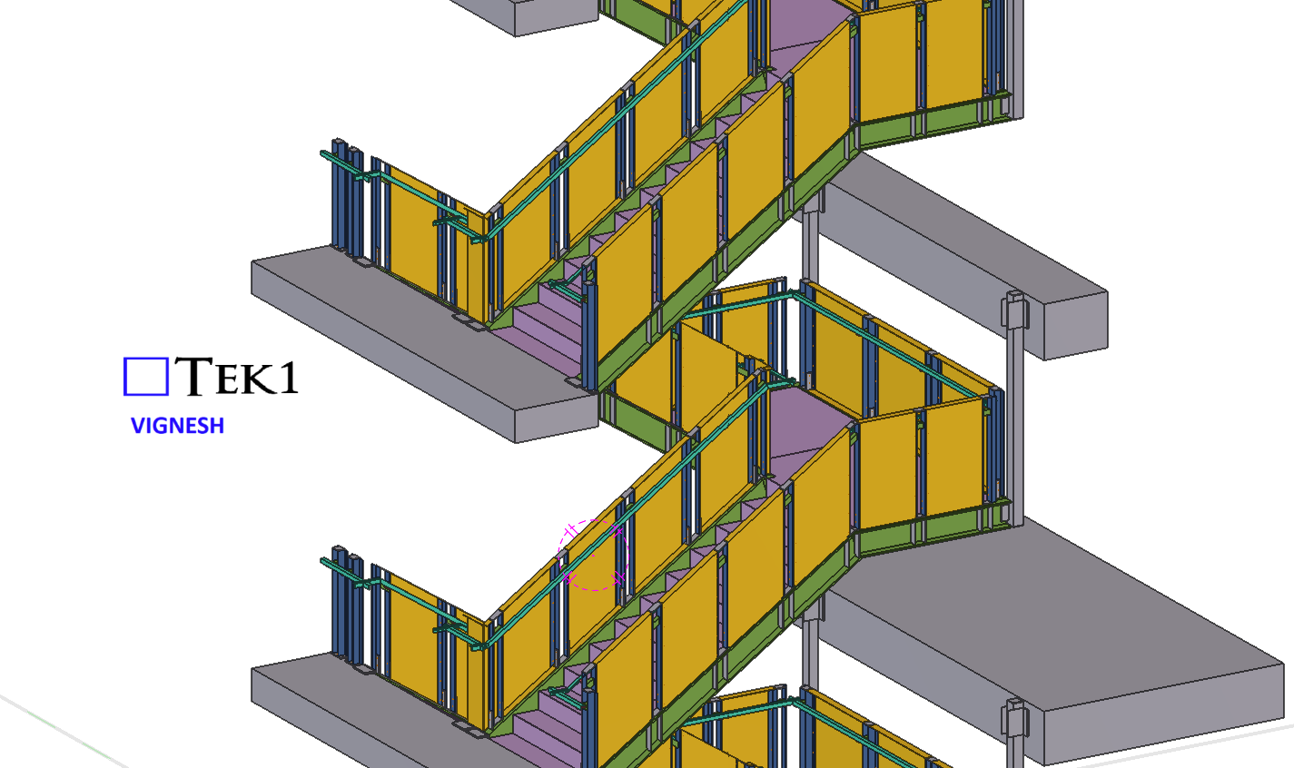
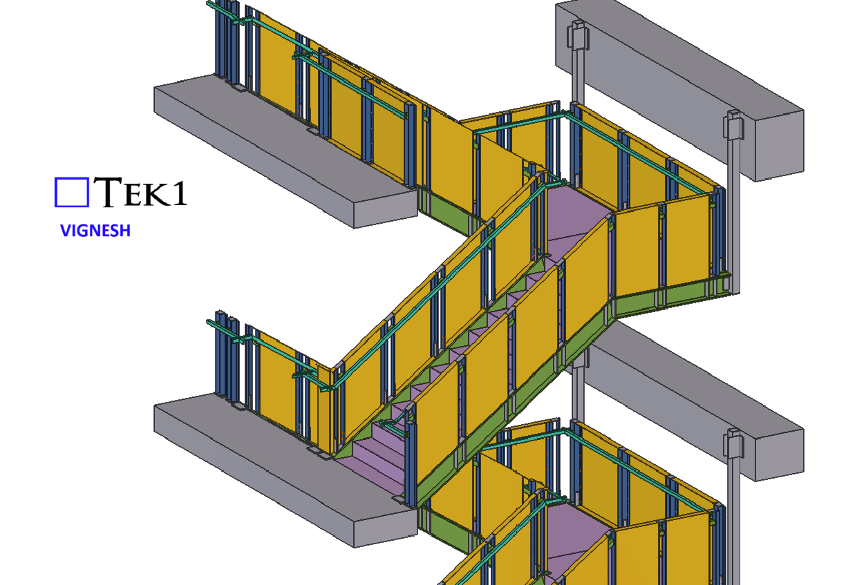
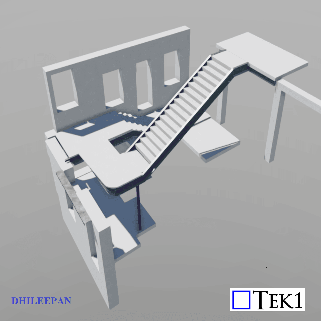
When designing a staircase, one of the most overlooked aspects is the correct distribution of risers, especially when integrating a mid-landing with a falling finish.
Understanding the Mid-Landing Design:
In this case, the staircase consists of two flights turning 180° with a mid-landing. The purpose of this stair is not only to provide access between Ground Floor (GF) and Level-01 but also to facilitate movement to the mezzanine level from the mid-landing. The design for the mid-landing incorporates a 10mm plate with a 50mm paver on top. However, an important requirement was added: allowing for a fall in the paver to prevent water stagnation. We received an instruction to keep the landing RL 20mm lower than the door near the mezzanine level to incorporate falls in the paver.
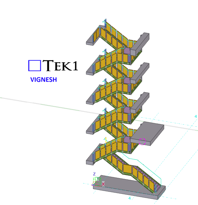
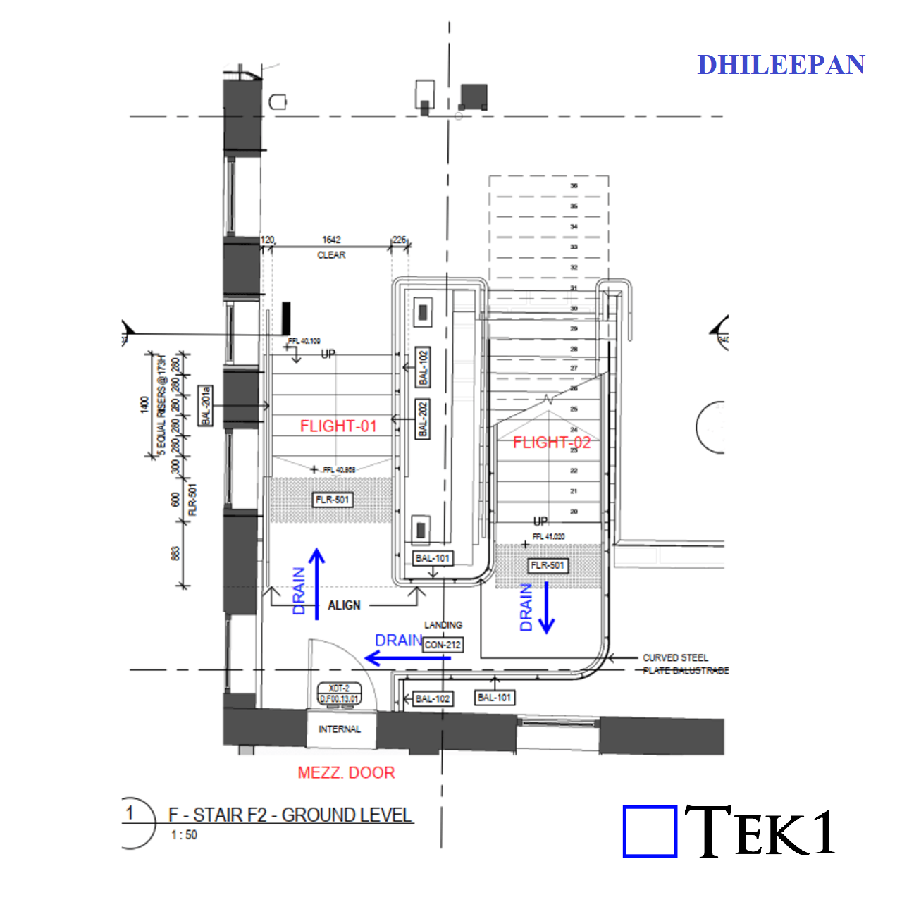
Common Mistake in Flight-02 Design:
For a steel detailer, just paver RL which is 20 mm below the door level & 50mm paver thickness is enough to place the steel below. The sloping surface in the paver will be taken by some other parties. But the key thing to notice here is, the slope continues to the bottom of flight-02 as well. At the end of Flight-01, the paver thickness remains 50mm. Near the mezzanine door, the thickness increases to 70mm (50mm + 20mm fall). A frequent error occurs when designing Flight-02. Many assume the risers should be evenly divided between Level-01 FFL (Finished Floor Level) and the RL of the mid-landing, neglecting the impact of the paver thickness variation.
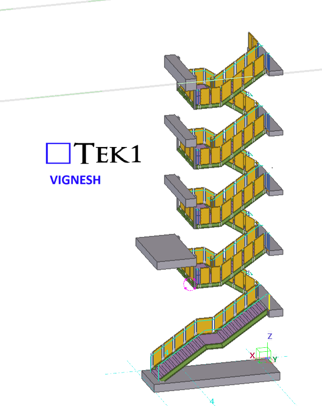
To achieve the correct stair profile:
The mid-landing RL should be set based on the increased paver thickness near the flight-02. Flight-02 risers should be distributed between Level-01 FFL and the actual top surface of the paver (which is 70mm at the bottom of Flight-02, not 50mm). Else, the first riser in the flight-02 will be comparatively smaller than the rest of the risers.
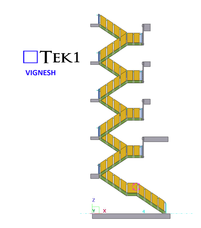
Key Takeaways for Stair Detailing:
Account for varying thickness: Do not assume uniform paver thickness; adjust accordingly at different points.
Correct riser distribution: Ensure the risers of the second flight are calculated based on the actual mid-landing RL, factoring in paver thickness variations.
Clarify detailing instructions: Steel detailers do not need to model the paver exactly but must ensure the mid-landing RL is accurately set.
By paying close attention to these details, staircases can be designed more efficiently, reducing costly rework and ensuring a smooth construction process. Proper coordination between architectural and structural teams is essential to avoid misalignment and achieve a seamless build.
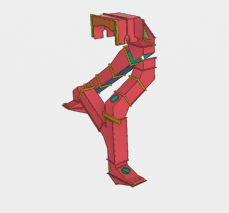
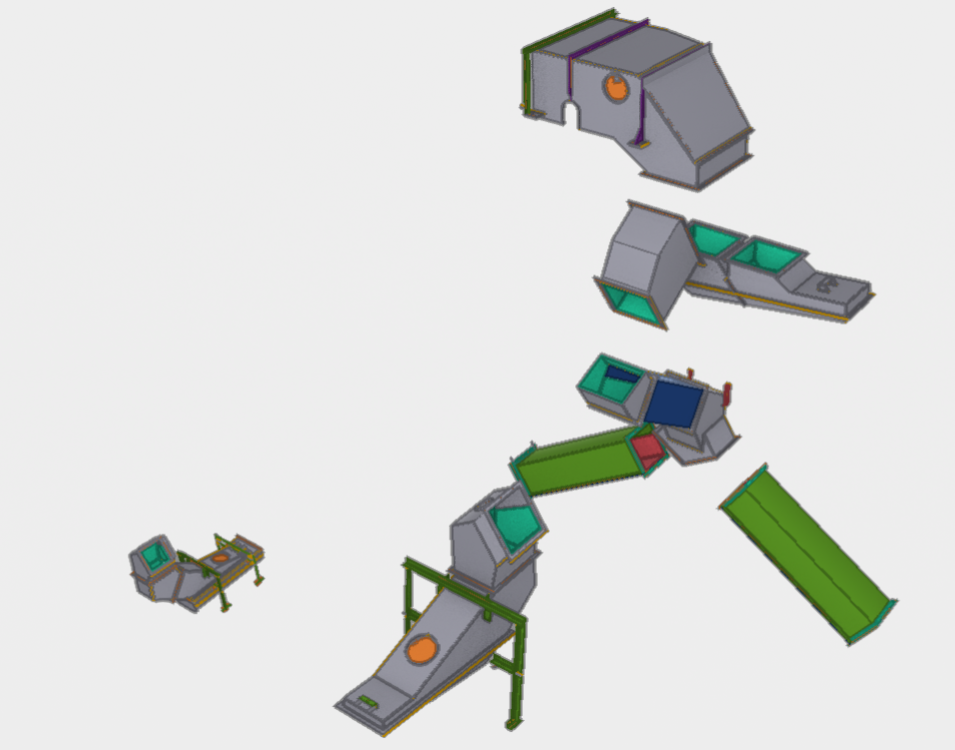
Input information was an Inventor model and pdf drawings
We have extracted the information from inventor, cross checked with pdf drawings, Checked constructurability, Resolved design details so that items can be fabricated at lowest cost.
These chutes were submitted for approval, and was approved without any issues.
Eventhough these chutes are for grain transfer, mining projects have similar requirements.
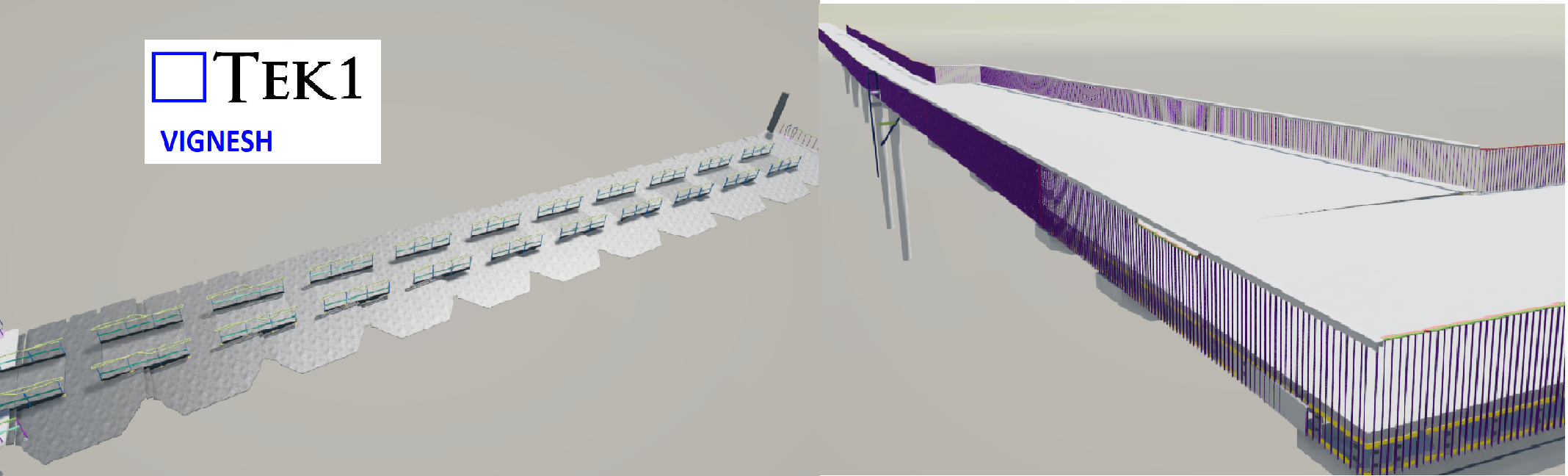
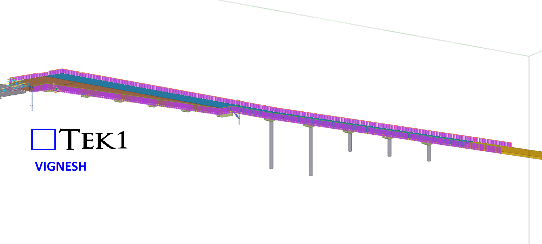
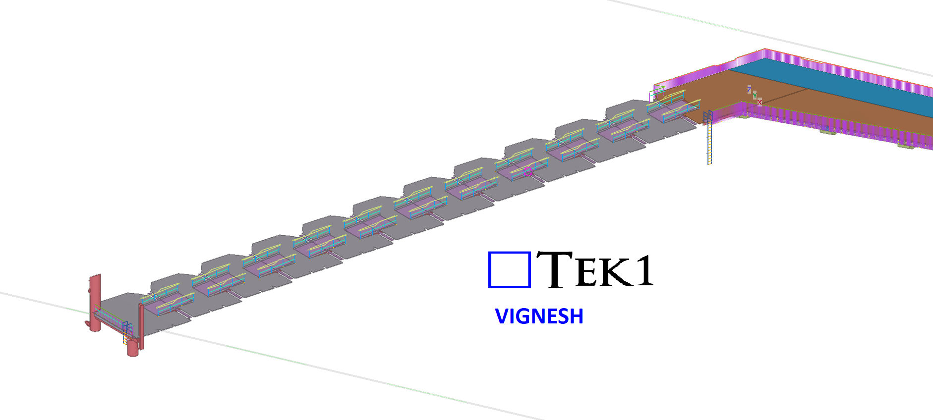
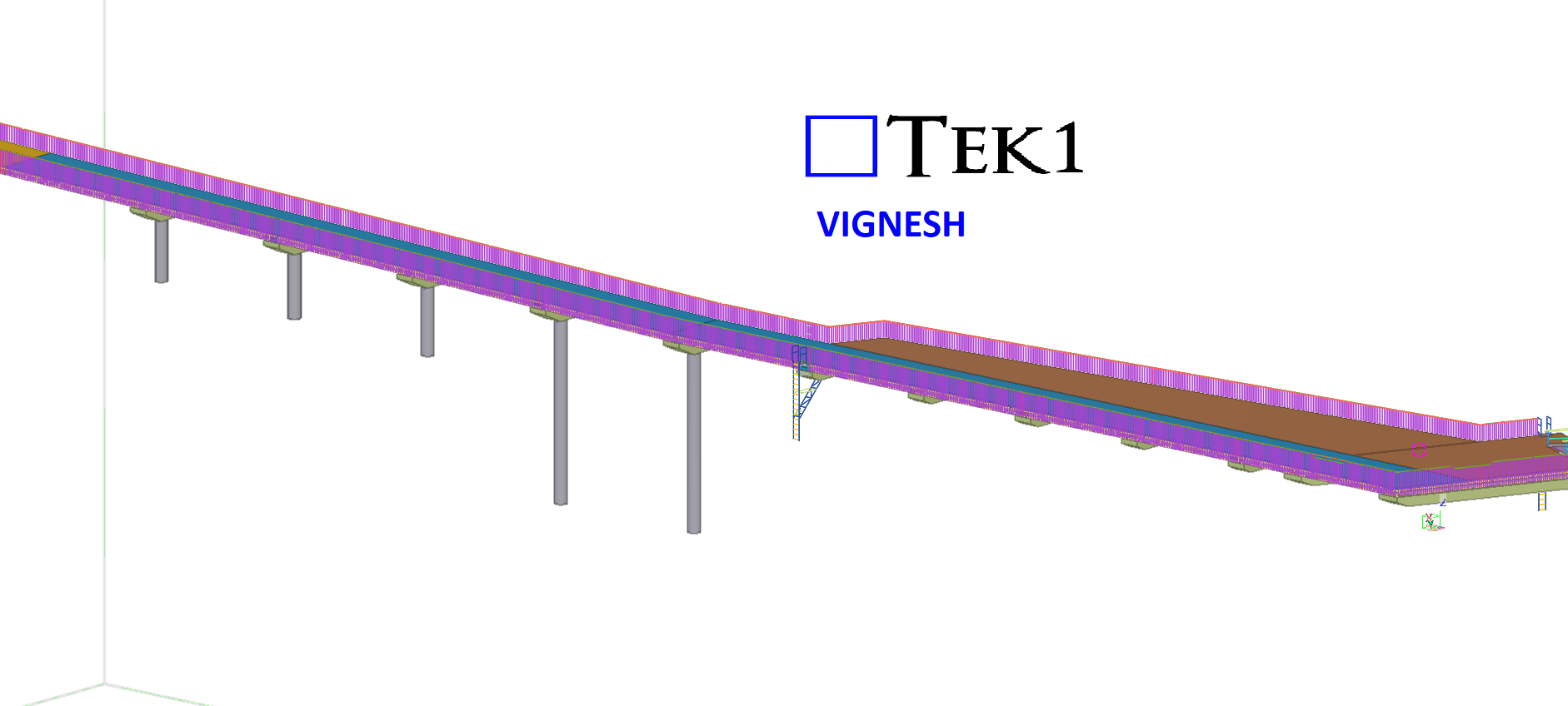
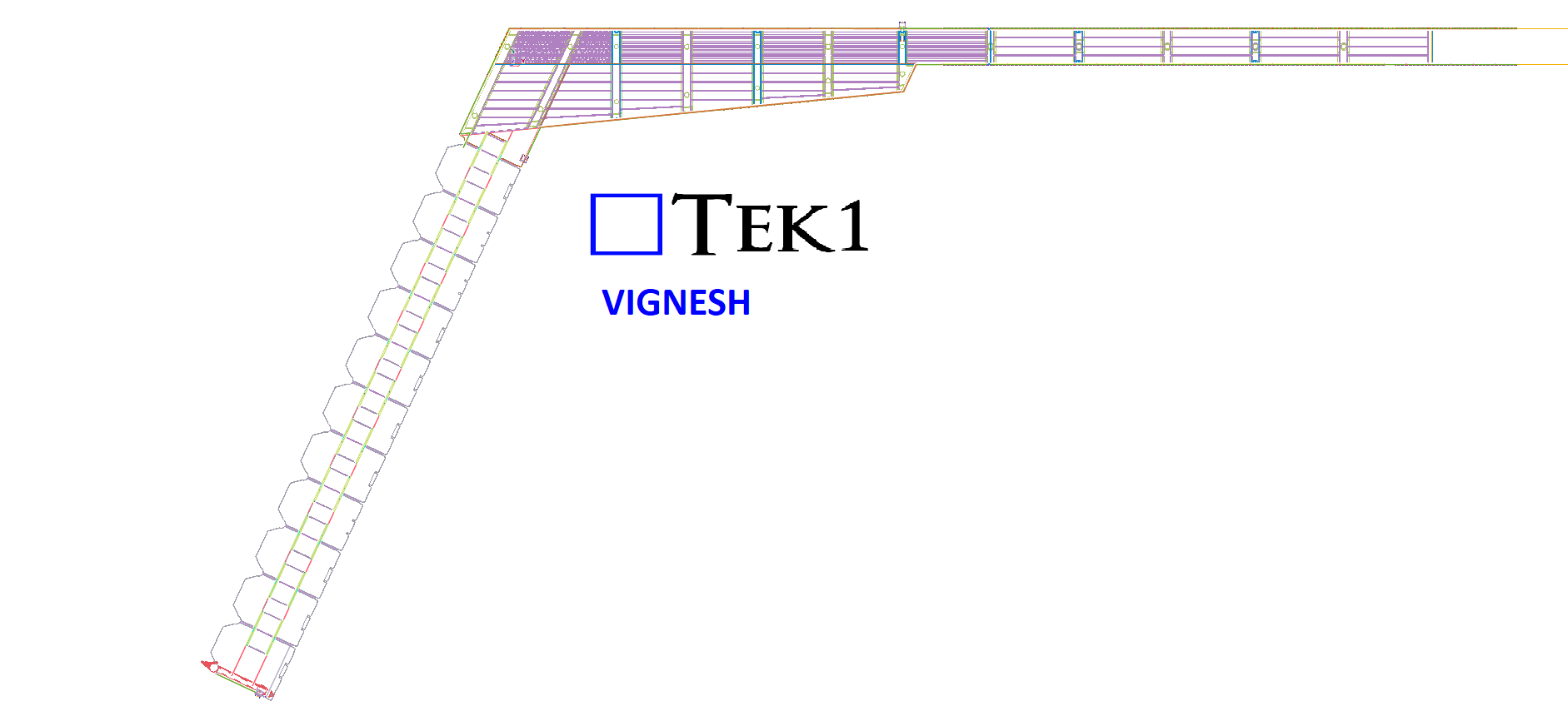
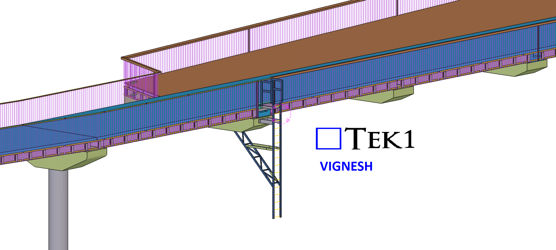
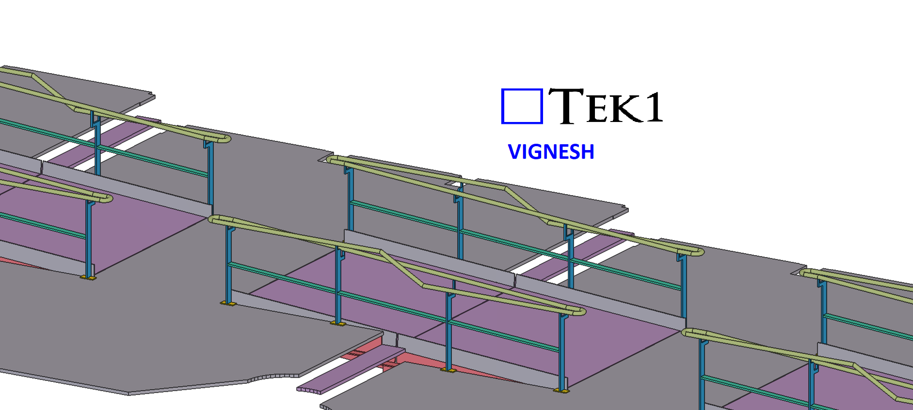
This was a complex project, but we successfully delivered it. Our scope included the balustrade around the bridge, which needed to be provided in multiple panels. By utilizing advanced modeling techniques, we were able to complete it within a significantly shorter timeline.
Since the structure is above the sea, we provided several cost-saving ideas for both erection and fabrication to optimize the process.
This was drawn by Tek1 (Vignesh), if you want shop drawings for a project you are working on, feel free to call Koshy on: (03) 9560 6397.