Here are some planters we have detailed for Straight UP. There are some steel planters and brick planters here. Each planter brings a unique aesthetic and functional appeal to your garden or patio.
This page show cases some of the Steel Detailing projectgs completed in Melbourne, Sydney, WA, Brisbane Tek1 has completed
Here are some planters we have detailed for Straight UP. There are some steel planters and brick planters here. Each planter brings a unique aesthetic and functional appeal to your garden or patio.
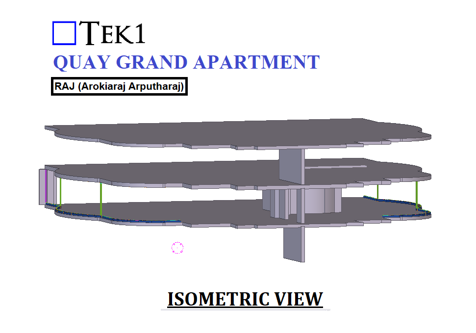
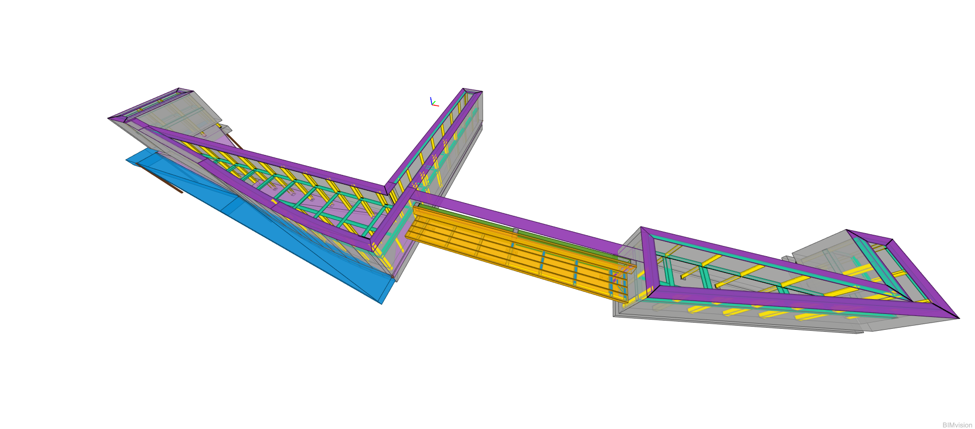
Imagine trying to build a complex 3D structure using only flat, 2D puzzle pieces—every cut, weld, and alignment must be perfect. That’s exactly the challenge we faced with the Orange Rope project, where 3D CAD models had to be transformed into precise 2D fabrication drawings. How did we tackle this engineering puzzle? Let’s dive in!
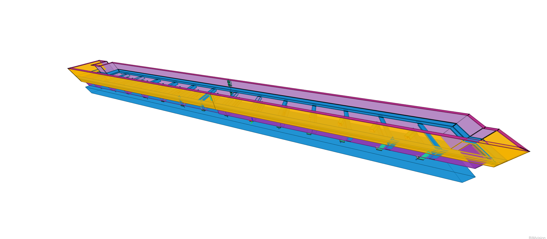
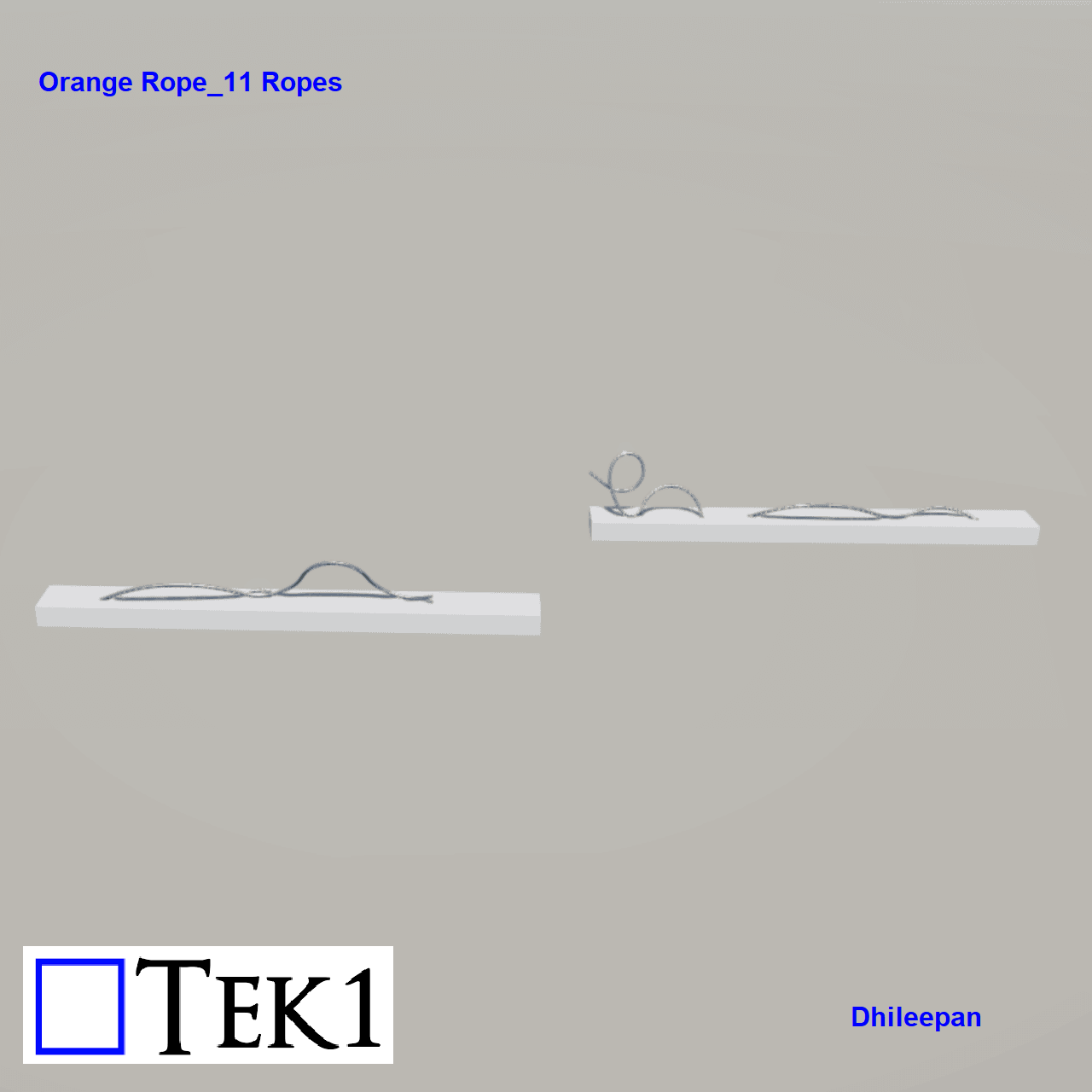
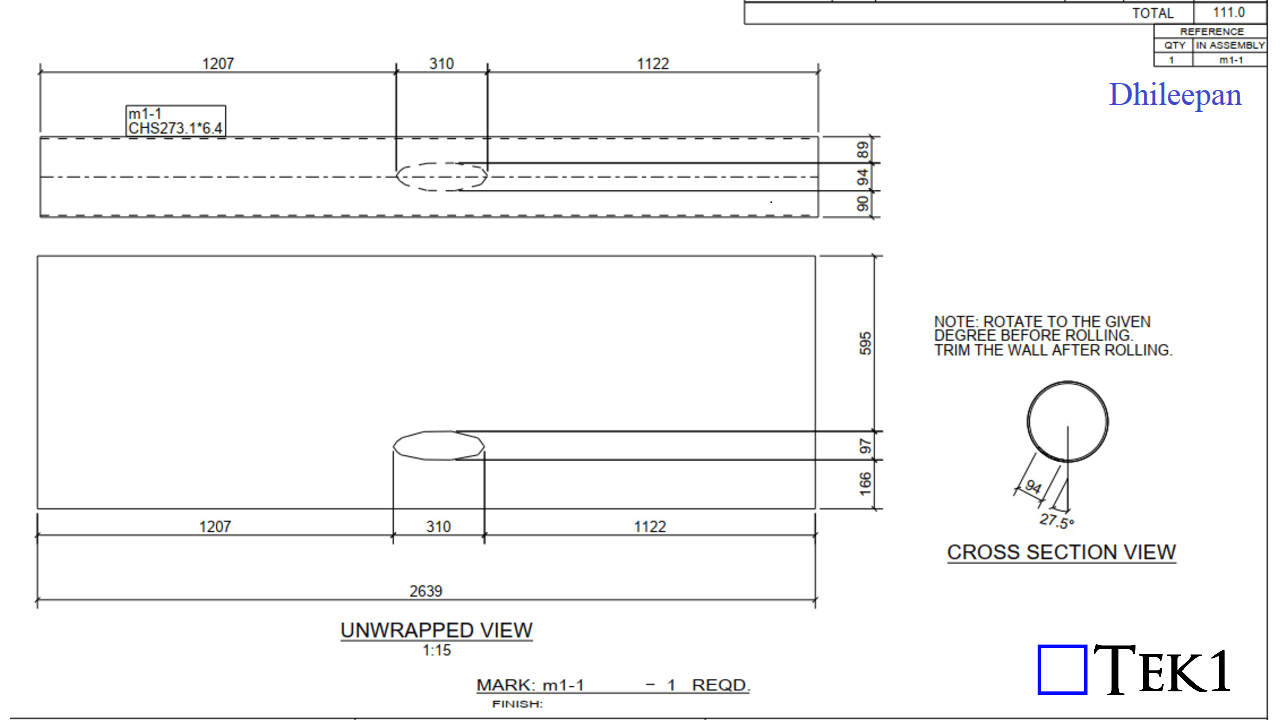
The “Orange Rope” is a series of rolled pipes placed between the piers in a bridge. This project involves a total of 11 ropes, with the following images showcasing a sample of a rope.
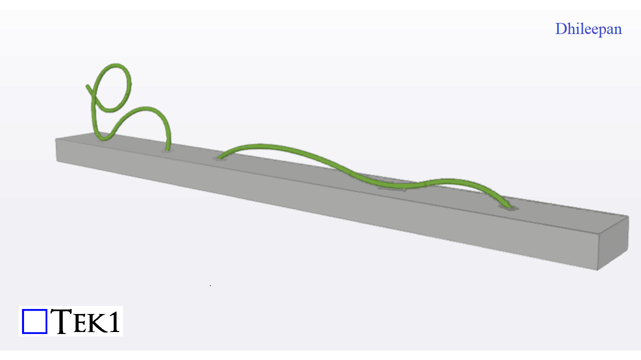
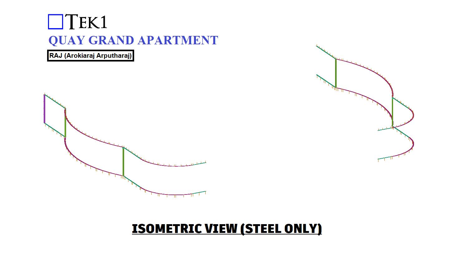
The initial input received was in the form of 3D CAD drawings, while the required output consisted of 2D drawings for fabrication. To achieve this, the 3D ropes were broken down into a series of 2D pipe members, which were then welded together to recreate the 3D structure. Each rope was divided into 4 to 5 assemblies, each containing multiple 2D pipes that, when assembled, would form the final 3D shape.
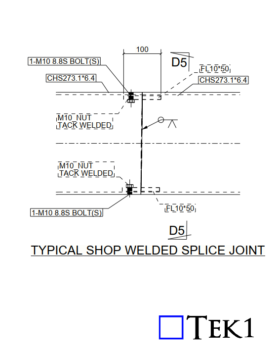
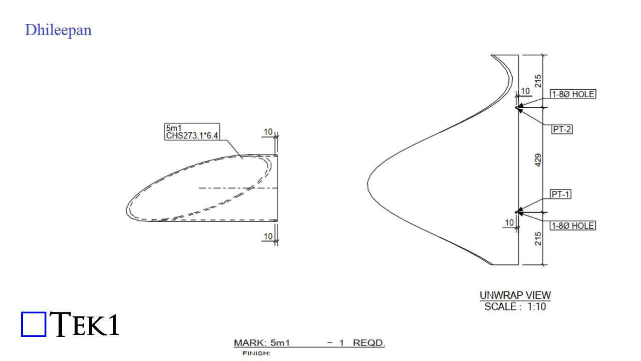
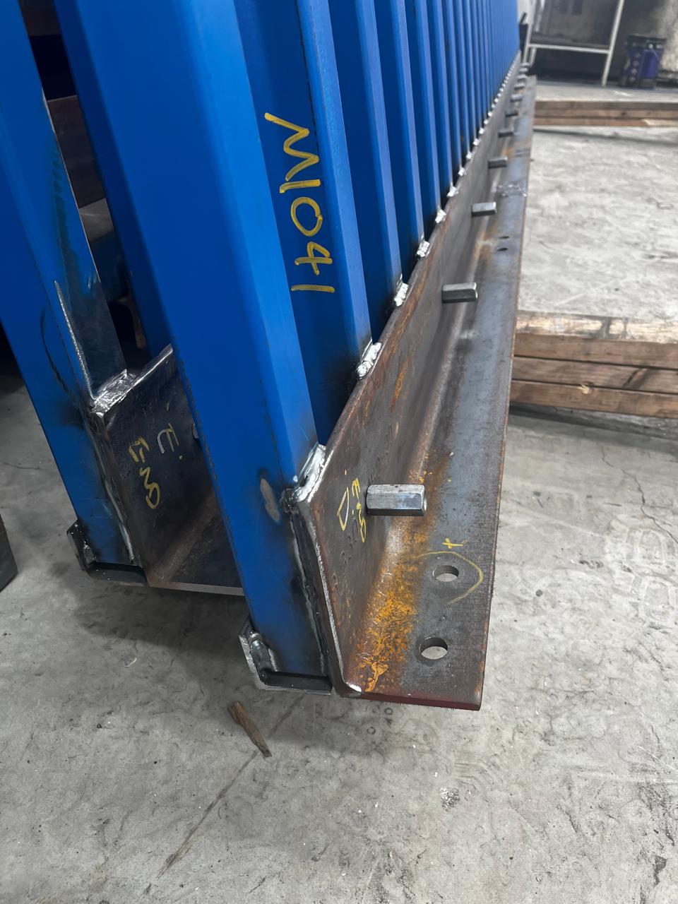
Welding each 2D pipe in the correct position to form the 3D structure presented a significant challenge. With intricate dimensions, aligning each pipe manually would be nearly impossible. To tackle this issue, a splice system was introduced. This system involved a welded plate with a nut affixed at the bottom of one pipe and a corresponding hole in the adjacent pipe. By bolting the pipes together through these holes, proper alignment was ensured before welding. Once the pipes were secured and welded, the bolts were removed, and the holes were plug-welded for a seamless finish.
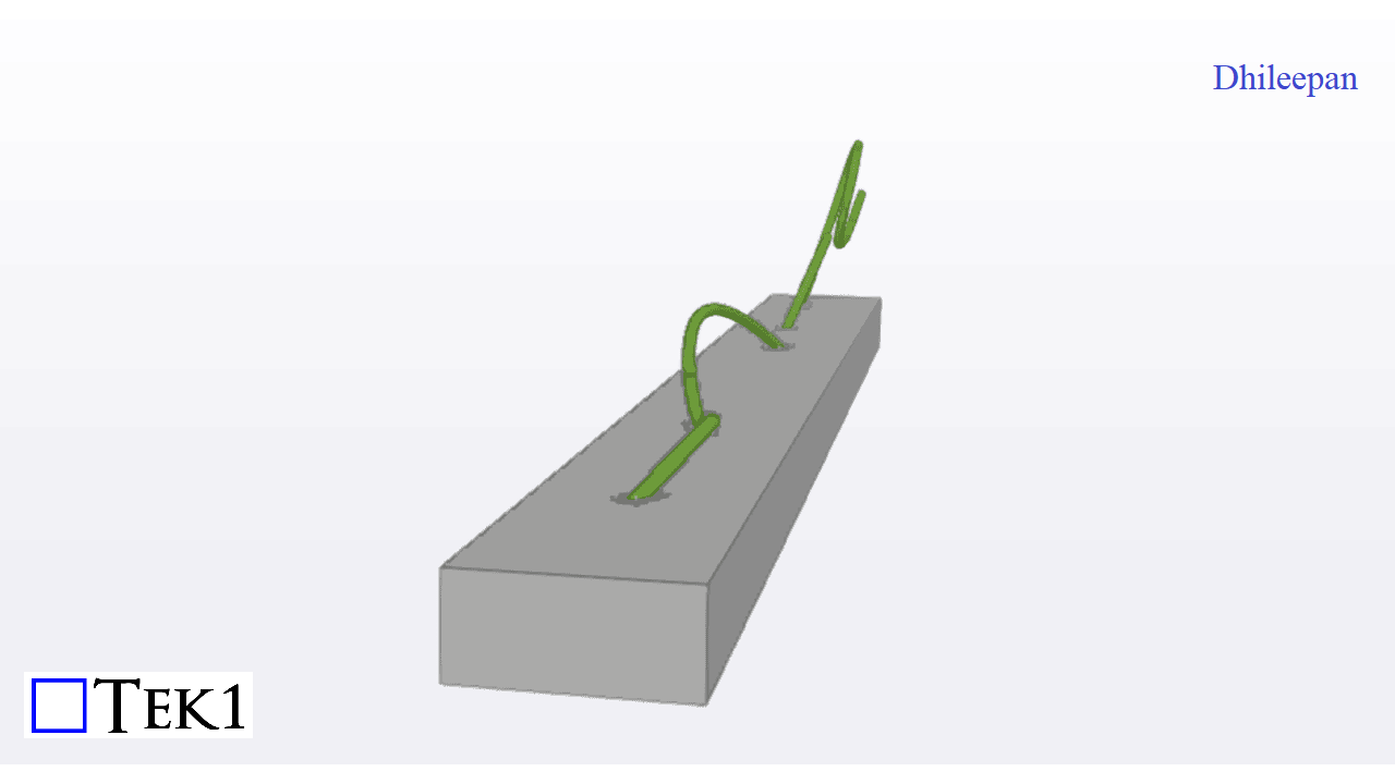
Another major challenge was the presence of asymmetrical cuts in the pipes for fixing them onto the base plates. To ensure precise cuts, unwrapped views of the pipes were provided. These unwrapped views were printed on paper at a 1:1 scale and then wrapped around the pipe. This method allowed for accurate cutting directly from the template, ensuring proper fitment and alignment during installation.
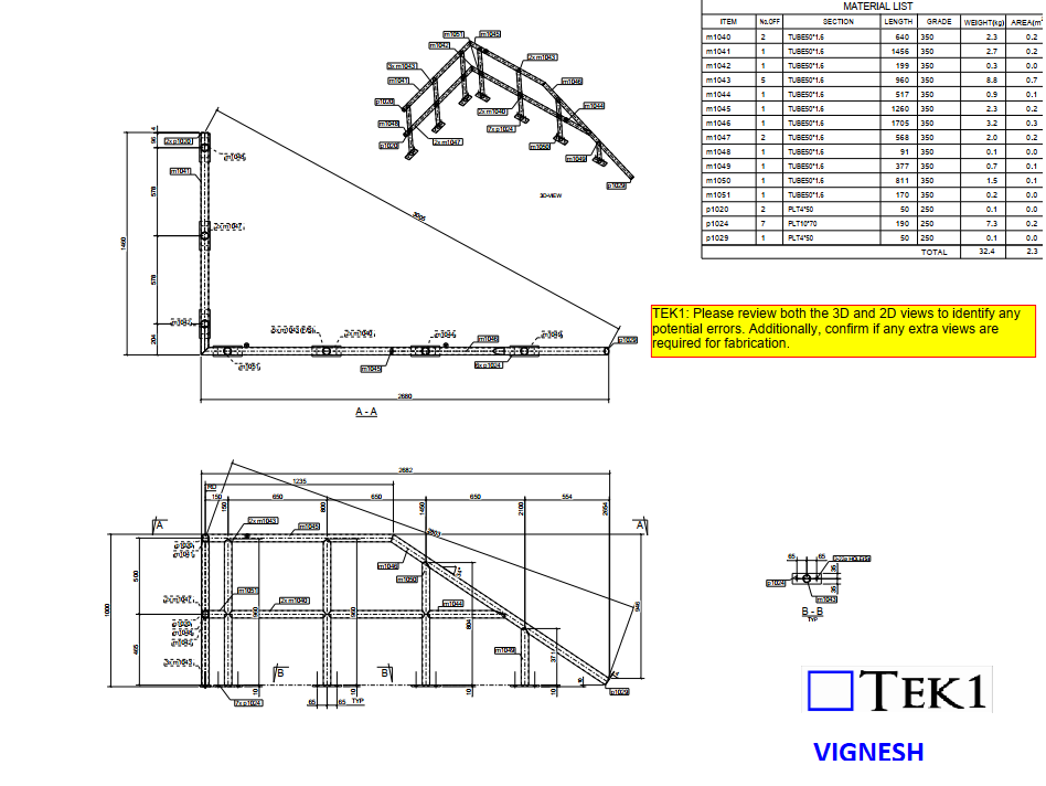
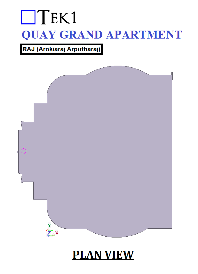
Please review both the 3D and 2D views to identify any potential errors. Additionally, confirm whether any additional views are required for fabrication.
Sounds fine, right? But here’s the catch—is it actually possible to fabricate with these views?
If we fabricate by 3D view alone, there might be a potential error. In reality, the fabrication needs to be done upside down.
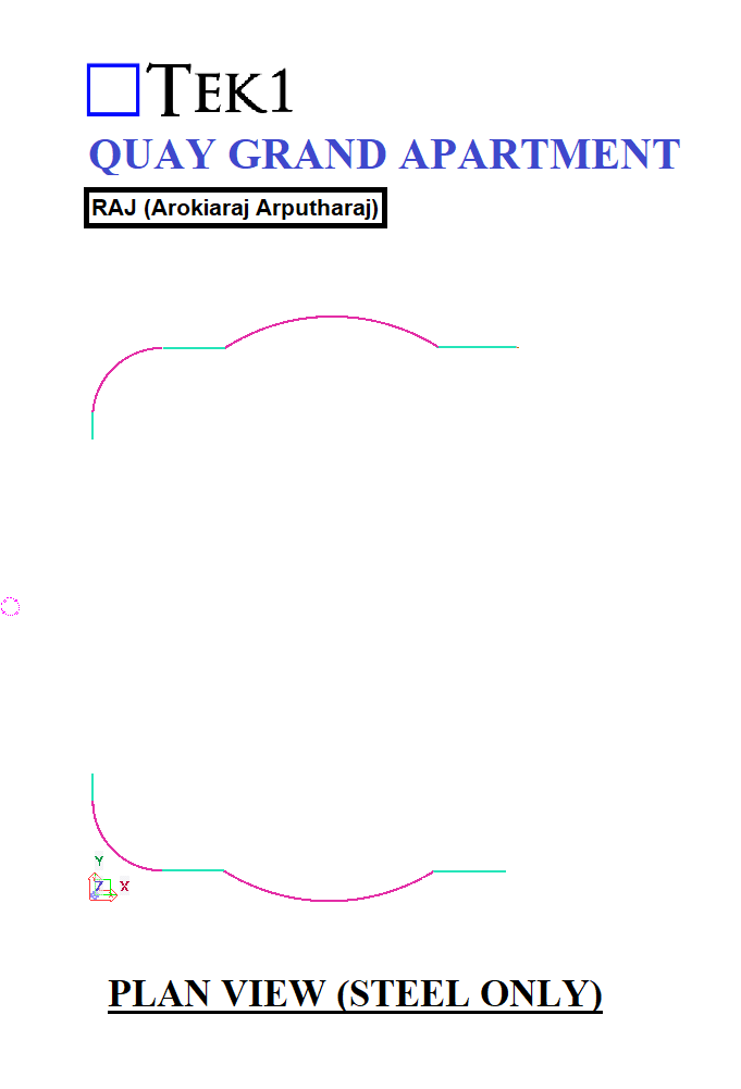
The Right Approach
We need to provide an additional section view C-C and ensure the 3D view is correctly oriented.
Actually, in the above drawing shows, the 3D view is placed as the underside view, which may visually appear as downside up.
Please review correct drawings attached below.
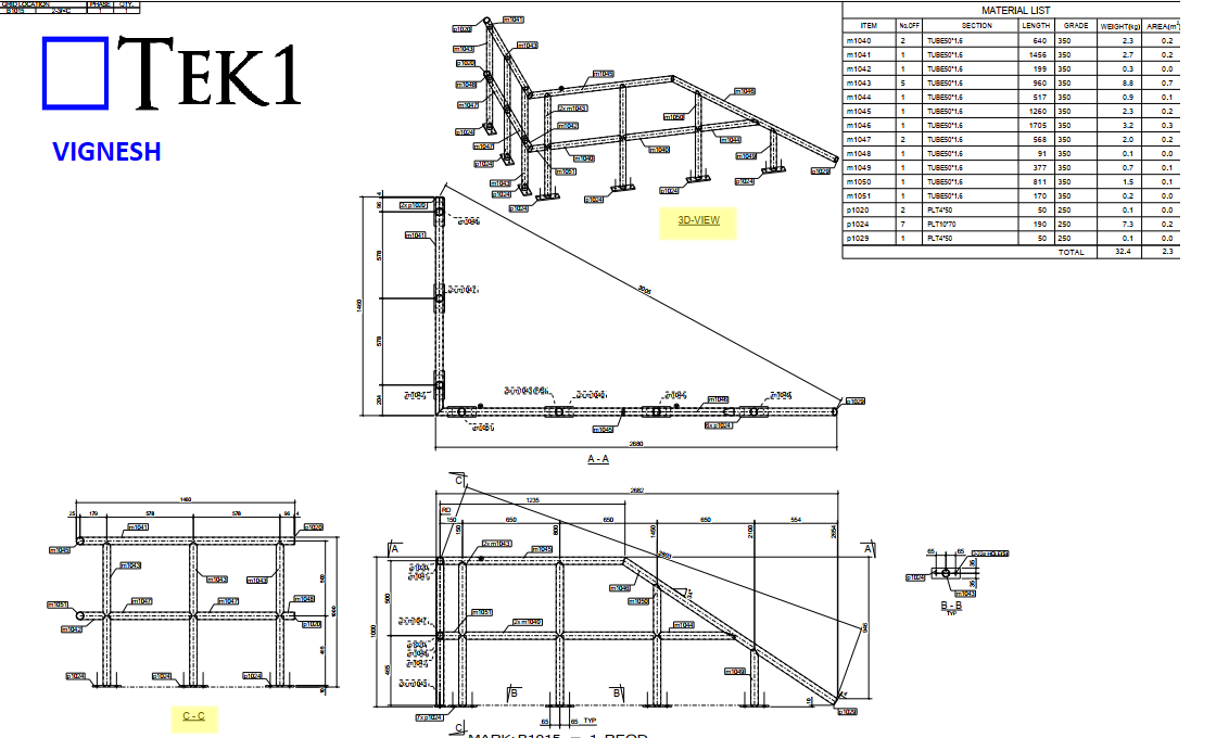
Always make sure any potential confusion is resolved before starting fabrication.
So next time you see a similar detail, take a closer look—is it actually can fabricate?
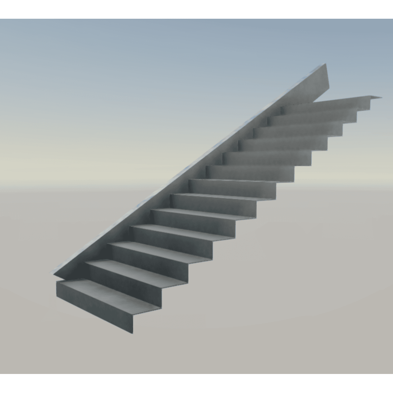
Imagine you’re reviewing a staircase drawing, and you see this note:
“8 THK CONTINUOUS FOLDED PLATE TREADS AND RISERS.”
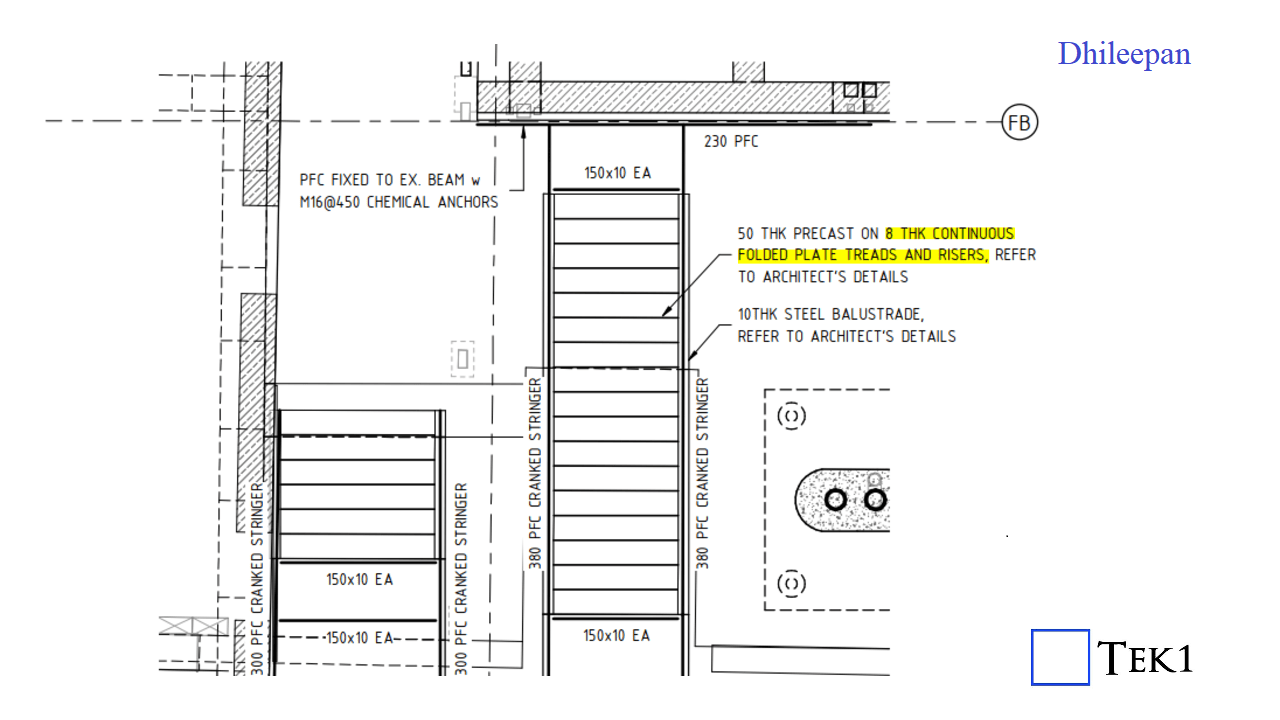
Sounds fine, right? But here’s the catch—is it actually possible to fold a single plate continuously for an entire stair flight? 🤔
A plate cannot be folded continuously to form multiple stair treads and risers because:
Instead of one continuous folded plate, each tread and riser should be a separate, single-folded plate. These individual elements can then be welded or bolted together to form a strong and practical staircase.
So next time you see a similar detail, take a closer look—is it actually buildable?
This is Challenging Metal Works Project by Tek1 for one our long standing clients in Melbourne
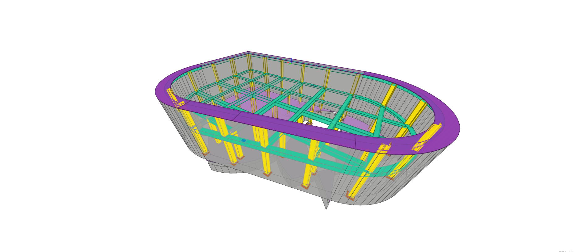
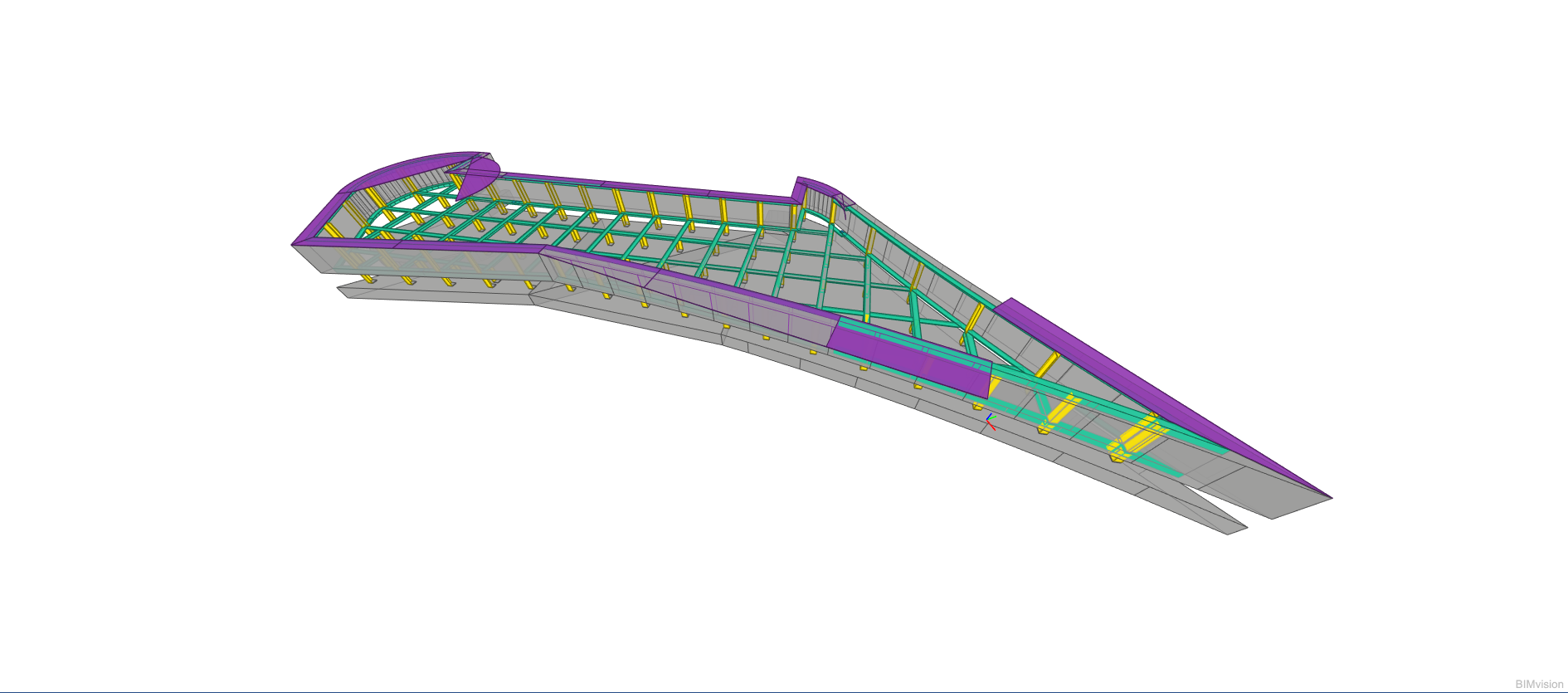
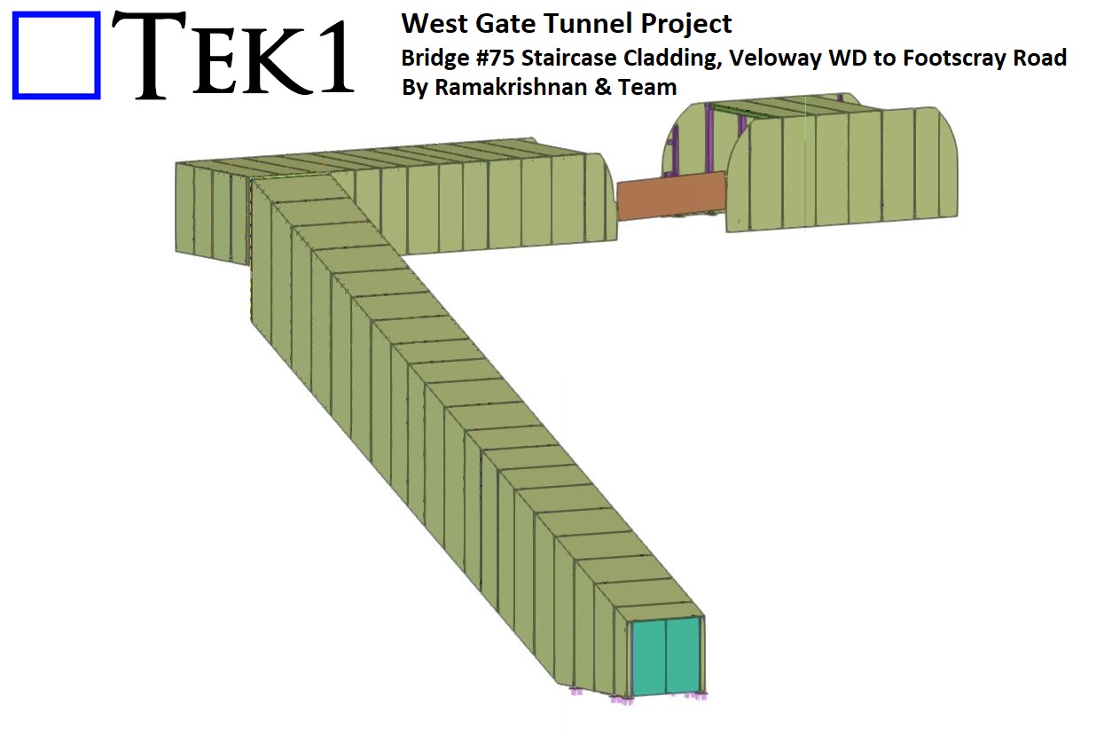
TEK1 is share our involvement in the West Gate Tunnel Project – specifically with Bridge #75 Veloway WD to Footscray Road. As part of this prestigious infrastructure development, we successfully detailed the steel staircase cladding, adding both functionality and visual appeal to the project.
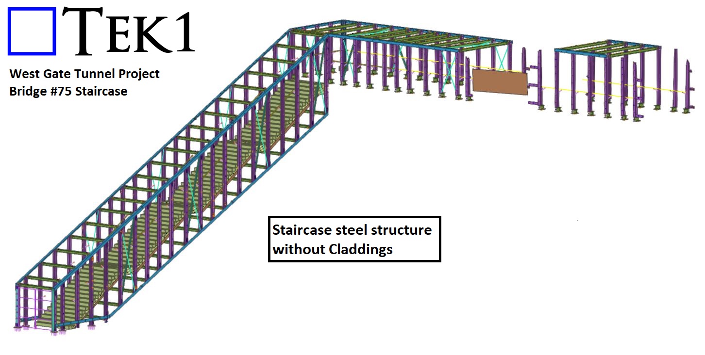
The cladding is securely fixed to the main steel structure of the staircase, requiring precise coordination between steel and aluminium detailing. Our team at TEK1 ensured that all fixing points were carefully detailed to accommodate the unique requirements of perforated cladding, maintaining structural integrity and ease of installation.
The aluminium cladding for the staircase not only adds to the project’s aesthetic value but also demonstrates our expertise in combining materials for functional and visually striking results.
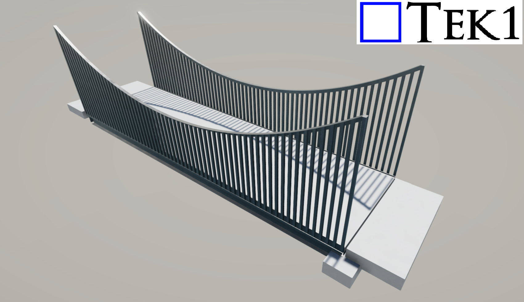
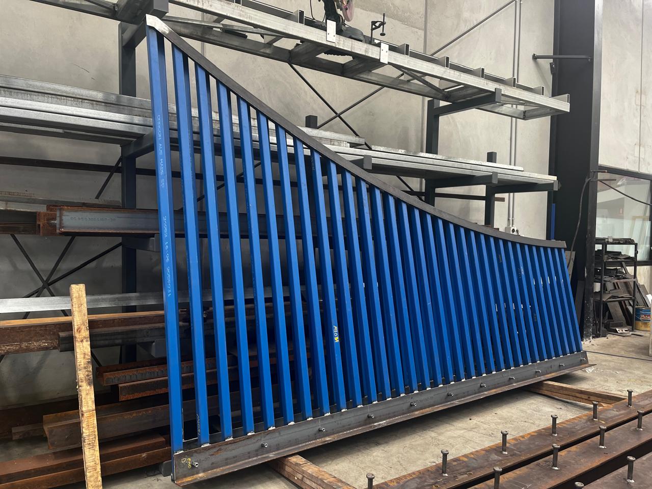
As a steel detailer, nothing compares to the satisfaction of seeing your detailed model come to life. I recently had the opportunity to witness the fabrication of one of my detailing projects in Australia. Balustrading for Foot Bridge
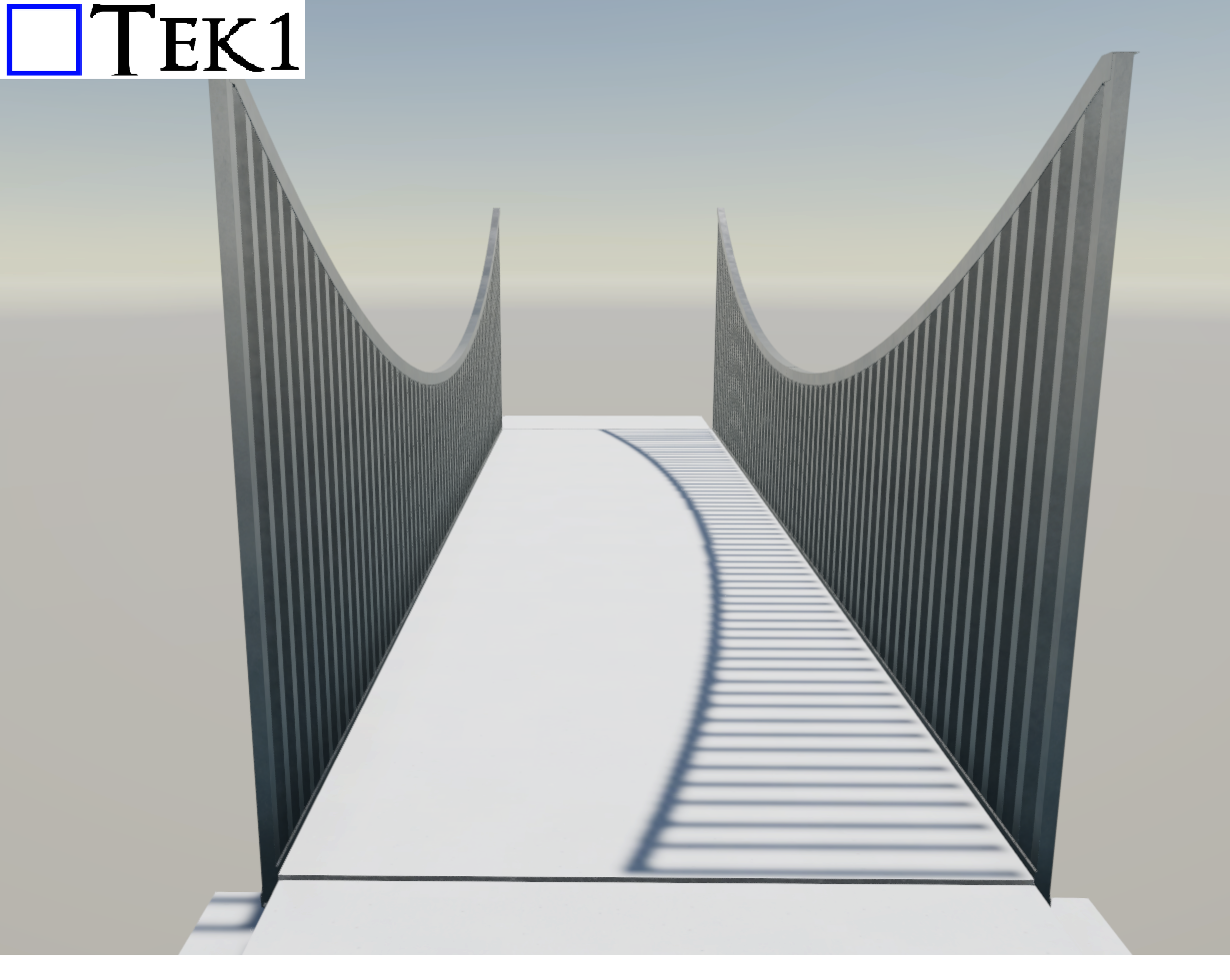
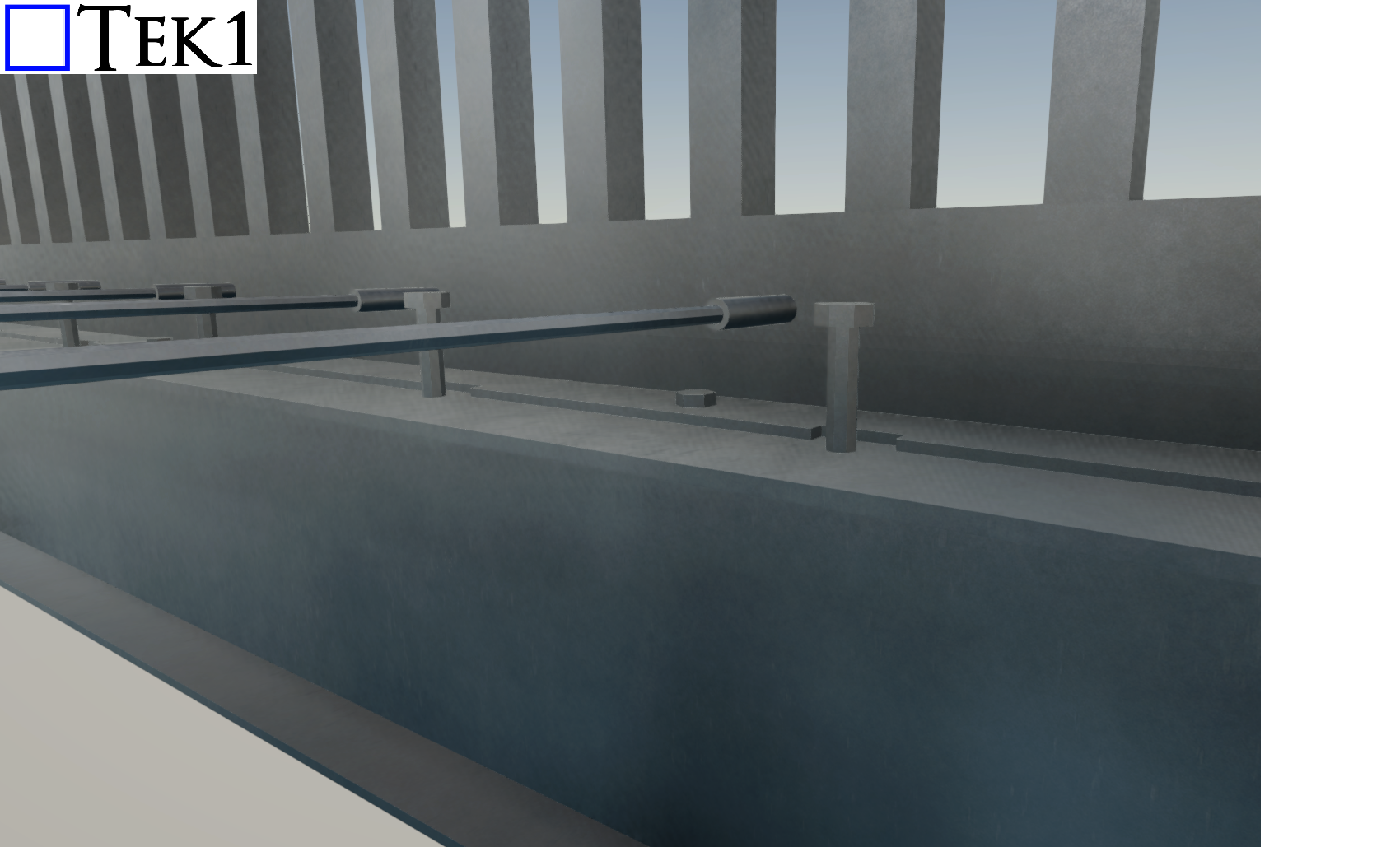
The detailing was executed seamlessly, with no challenges for the fabricator or erectors. It was fulfilling to see the effort and attention to detail pay off in real-world application.
This project was detailed a while before. However I am posting this now
We have detailed transfer structure, conveyors, Chutes, Vibrating Grizzlys on this particular projects. These Items are typical for mining projects. There is a fair bit of care required when it comes to bracing to avoid weld clash.
At Tek1, it is our standard practice to check all handrails , stairs, ramps ladder to relevant standard. We do not simply go by the Engineer Architect drawings. We check whether it will comply.
Actually, once can simply tell us, put a stair here, give us the heights and spacing available, we could detail a stair for you, which will comply to Australian standards (AS1657 or AS1428 as the case may be)
This video show cases a few elements of the mining structure.