Month: June 2017

  • AS 1428 – Section 11 – Nosing and Tread Requirements for Stair Construction (Public Access)

    We continue to release our in-house precis on Stair way construction. Reading the standards is terribly tedious so we have developed a way to easily cross check the requirements and to make sure that stairs are built according to standards.

    Unfortunately it’s too common for us to see designers produce drawings which simply do not comply to the required standards. So it is of the utmost importance that fabricators are able to: (i) know and understand the standards and to independently verify that their drawings do comply. Only a fool would 100% trust in an architect to draw to standards – we’ve seen it way too often. You, the fabricator have to check everything yourself. Here are some of the in-house memos that we use to ensure that our stairs always comply:

    We wish to share it with the world – and we hope it helps you immensely:

    TEK1 AS 1428 11.1 Standards for Stairs

    I hope you find it of benefit and great use.

  • Maximum Frame sizes (Steel Detailing Tips)

    Maximum Galvanizing size generally available in Australia

    • 1400 WIDE X3100 DEEP X 12000 LENGTH

    Maximum width for road transport (laid flat on bed is 2500m)

    Please check out both the documents below.

    http://www.legislation.act.gov.au/di/2006-120/20060623-28031/pdf/2006-120.pdf

    https://www.tmr.qld.gov.au/Safety/Vehicle-standards-and-modifications/Loads-and-towing/Projecting-loads.aspx

  • In Process vs Out of Process

    There seems to be a lot of confusion with folks about the difference between using the AutoCAD .net API vs the COM Interop API. They both hope to do the same things, but via different ways. Given a choice, I’d always recommend using the .net API because it is much more powerful.

    In process – .net API

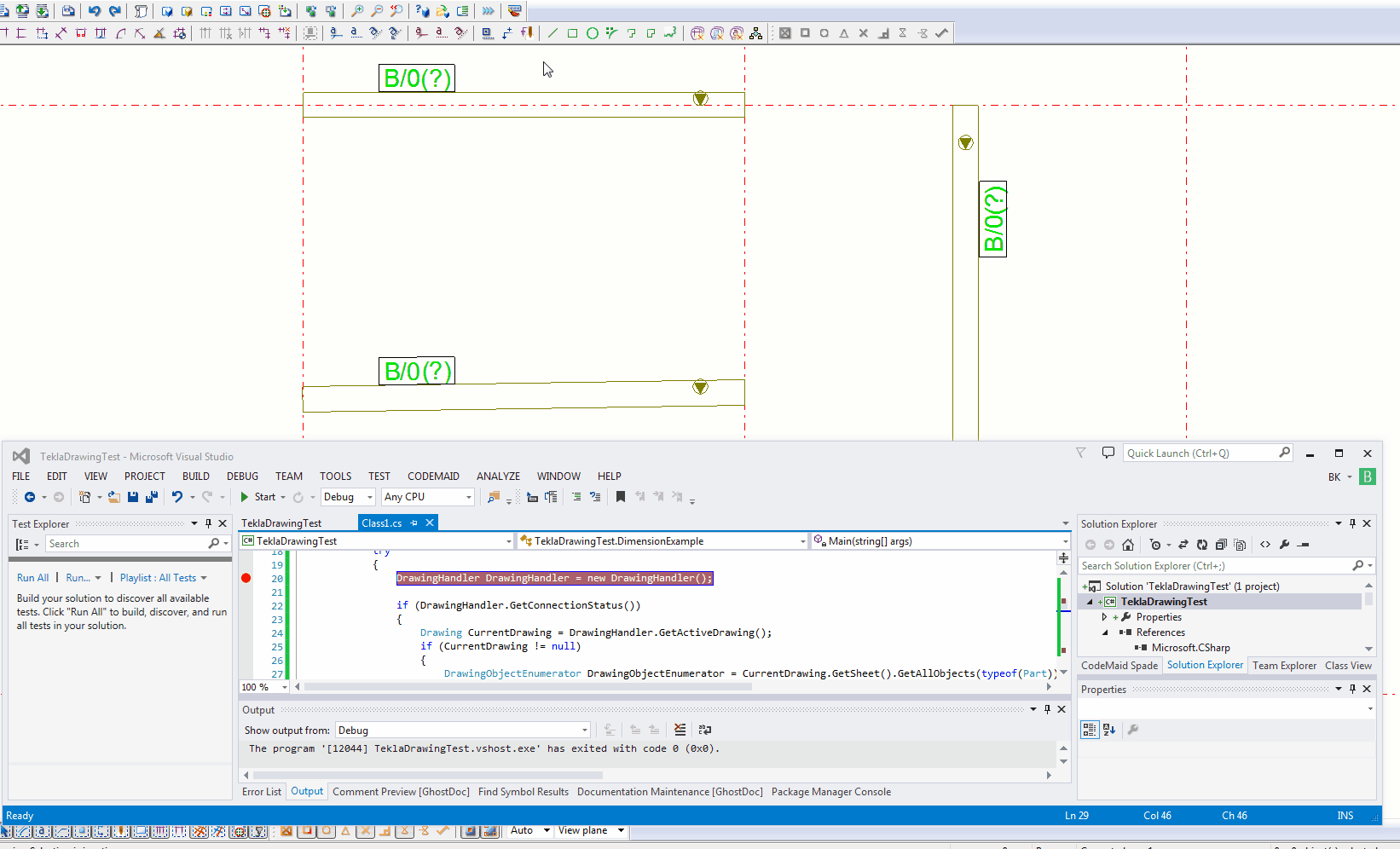
    This means that the user has to first open AutoCAD. i.e. double click on the AutoCAD icon and start up AutoCAD. once AutoCAD is open and a drawing is opened, then the user has to type in a command: “NETLOAD” and has to select the a file – the result of all your programming/coding efforts. once that file is selected the user then has to run the command “AddLine”. the command will run as you have coded it. in order to do it this way you will need the .AutoCAD net API

    Out of Process – COM InterOp

    In this case, you don’t necessarily have to manually open AutoCAD up. you create your own program, and you open it (much like you would open MS word etc) and your “AddLine” command would run without you, as a user, manually opening AutoCAD and netloading etc.. if you’re going down this path you need to use the COM interop API.

    Using Both

    If you really want to use the .net API, but did not want to manually netload, then you can use a combination of both of the above:

    From the documentation:

    If you need to create a stand-alone application to drive AutoCAD, it is best to create an application that uses the CreateObject and GetObject methods to create a new instance of an AutoCAD application or return one of the instances that is currently running. Once a reference to an AcadApplication is returned, you can then load your in-process .NET application into AutoCAD by using the SendCommand method that is a member of the ActiveDocumentproperty of the AcadApplication.

    As an alternative to executing your .NET application in-process, could use COM interop for your application.

    Hope this clear things up for you.

  • How to insert Reference Models into Tekla

    Wouldn’t it be handy if we could pro grammatically insert reference models into Tekla? Well you can now do so quite easily. And if you want to see a video demonstration, here it is:

    Here is the code which does the hard work. (You will of course add the appropriate references and directives):

  • Adding a Dimension to a Beam – Drawing – (Tekla Open API Tutorial)

    This is an example of a hello world program which dimensions a beam. I found this code in the Tekla Drawing Samples folder.

    You can see it in action here:

    How to dimension a beam using the Tekla Open API (c#)
    How to dimension a beam using the Tekla Open API (c#)


    Let’s walk through it:

    1. We have to get the relevant drawing.
    2. Then we have to get the relevant part we want to dimension.
    3. Then we get the view associated with the part.
    4. We save our current transformation plane, and we set a new transformation plane to the particular view’s display coordinate system.
    5. From here, get the part’s identifier and we select the ModelObject in the model itself – to get the relevant coordinates of the Beam we want to dimension.
    6. Once we’ve used the identifier to get the Beam we are after, and to get it’s relevant parts then we create the dimension.
    7. Remember to save back the original transformation plane.
    8. Note: if you insert the dimension then I obtained an exception. I don’t think you need to insert dimensions when working on drawings.
    9. Note 2: if you forget to save the transformation plane back to the original, then you will find that you dimensions will go wacky, next time you run the command. Always remember to leave things as you found them!
    10. Note 3: You have to have the beam in the same plane as your view otherwise it won’t draw the dimension.


    Here is the code for your benefit:


  • Stair Outline Routine (AutoCAD .net + Code attached)

    An example of the type of stairs we draw. We do a lot of stairs. Both AS 1428 and AS 1657 compliant stairs.
    An example of the type of stairs we draw. We do a lot of stairs. Both AS 1428 and AS 1657 compliant stairs.


    We continue delving into our discussion of stairs. The boss hates it when I do things like this – releasing code to the public. But it’s too good not to share. Below is a routine you might find useful. We use it to model stairs – it’s super fast, and efficient. It allows us to try different things out and to discard what doesn’t work with ease. I’ve gone to the effort of drawing up an entire flight of stairs and then realised that I’m missing a tread. Then I’d have to redo the whole thing from the beginning. Once you have this outline done, the a good chunk of the work is finished.

    One of our many, many versatile routines:

    Here is a gif of the project:

    A Stair AutoCAD Plugin
    A plugin I wrote for AutoCAD. Written using c#.

    And here is the code for the benefit of study.

    I suppose I should refactor it, but I don’t think I’ll be changing it any time soon. So why worry?

  • AS 1428 Stairs-Handrails – Tek1 Compliance Checklist

    We do a lot of work on handrails – both public access (AS 1428) and also private access (AS 1657).

    Anybody can draw a staircase – and if you’ve ever fallen down some stairs, or if you’ve ever walked up some stairs which do not comply to any standards – then you’ll immediately realise the importance of having stairs that actually comply. It’s paramount for safety.

    Designs of non-complying staircases is something that we see all too often. All the time. The costs of fabricating non-compliant staircases is monumental. We’ve invested a lot in training staff to ensure they follow the standards. And for the benefit of the industry, here is a cliff notes version that our guys use to remind them of the requirements needed for public access stair handrails.

    It is a first class precise that allows detailers to quickly check compliance without wading through reams and reams of legislative like prose within the AS 1428. This precise will be the norm in the industry and is worth its gold. It was made right here by Tek1.

    Please see the attached pdfs and drawings below.


  • Why do we set copy local to false?

    When you first get into .net API programming – for AutoCAD plugins, you learn this cardinal rule: make sure the three AutoCAD dlls you refer to have copy local set to false.


    Why exactly is this the case? I couldn’t find a better answer than the one offered by Fenton Webb. Here it is in full:


    Take a second to look at the AcMgd.dll and AcDbMgd.dll in this folder…. Do you notice that they are much smaller than the ones in the AutoCAD installation folder? There is a big reason for this which is that since the 2010 release of the ObjectARX SDK, we have “liposuctioned” the managed reference DLL’s. I say “liposuctioned” because we literally sucked out the body of the code from each function in the assembly DLL. What we did to create these DLL’s was to actually ILDASM (MSIL disassemble) the original DLL’s, strip all the body code from them and then reassembled them using ILASM (MSIL assembler). OK, now why on earth would we do that, right? Let me explain: the WPF UI designer (and indeed the WinForms designer) in Visual Studio is pretty cool in that it does a great job of showing the design of the UI on screen obviously. The problem is that the designer does like a half-hearted parse of the code behind that controls the UI in order to work out things like how it’s displayed for instance, which when we reference the external AutoCAD managed DLL’s can cause unresolved dependency errors and thus stop the VS Designer from working properly. These dependency errors are caused by the fact that the ac*mgd.dll’s depend on acad.exe which of course the VS Designer finds impossible to load in order to resolve the dependencies. By using the “liposuctioned” assemblies in your project, all of the object definitions are in place to resolve designer parsing issues. You’ll be glad to hear that it still compiles, and loads too! Just as long as you keep the Reference property “Copy Local” set to false for each DLL.

    (Taken from Fenton’s WPF AutoDesk University course notes).

    #Tekla API #Autocad API #DOT NET 

    (more…)

  • Steel Detailing Tips: How to markup A Tekla BIMSight Model

    Download Tekla BIMSight

    Please watch this video on how to markup the Tekla BIMSight Model. It describes the 4 essential steps required to effectively markup a s bim sight model

    Most important is make your comment public, else when you send the BIMSight model, no one will be able to see your comments. Users can mark up the same model and return to you with their own comments.


    Watch the video below on how to send your marked up BIMSight Model to your clients.