There is a large number free way gantries across melbourne. Tek1 has detailed a good number of them very efficiently.
Here is an example of one such Gantry we have detailed for our Melbourne client in the SouthEast.
There are couple of types of gantries, very similar. The large span gantries have to be fabricated with a camber which is challange for the detailer and fabricator.
Managing weld distortion, transport etc are the challenges the fabricator will have solve.
Most of such jobs come with a very short delivery time between order and install, and generally high pressure jobs. Getting first time right is super important.
The key to this is to specify a chamfer value, and at least three points using the PolyBeam class. You must also provide a profile type that Tekla understands – otherwise you’ll get a bunch of straight lines.
Here’s some basic code to get you started:
You should be able to easily import, into Tekla, any curved Beam you want. The principal requirements are: (i) start point, (ii) end point, and (iii) also rotation. Start point and end point and centre point – this will not do: you will also need a third vector if you are going down this route, and I feel that it needlessly complicated. This can be obtained via any any means: CSV files, or directly with Rhino APIs (this might require programming in both Tekla and Rhino).
It is best to control your data source
If you read our past blogs re: CSV files – everything is contingent on how it is obtained. If you have rubbish in, you get rubbish out. We worked extensively with a party on the Westgate Tunnel, who promised .CSV files, but then provided me with corrupt and inaccurate data points, and did not provide the data in the agreed upon format. This makes for headaches and recriminations — and ultimately dissatisfied customers — but what can you do if they provide you with rubbish data that you cannot verify? So if you’re going down the CSV file route — then you need to know how the CSV files are being produced, and that there are not mistakes in them: e.g. missing columns, nonsensical data values, and that they are being produced programmatically etc. or at the very least have excellent lines of communication with your client to resolve these types of issues. Controlling the data source obviates these problems.
Or another problem I faced – you’ve agreed on CSV files, but the format changes each time an update happens. Someone changes the name of a column header – or they give you a file with irrelevant stuff in there. Every time you have to manually edit something, you’re introducing the possibility of errors. All of this can be solved by controlling the data source.
The Devil is in the Details
Again, as with most things, they seem simple at first but the devil is in the details: you gotta tackle the problem of rotation and also profile mapping and weird gotchas in Tekla – that are not documented. Then another important thing to manage:
Revisions and changes
How are you gonna manage this? How are you going to document variation hours? Likely you might have to add IDs to each member. This will have to be incorporated into CSV files from the outset. Or if you have the Rhino model in hand — then you could just see what has been changed programmatically: (i) are they IDs all the same, and (ii) if so, have they been moved. Now this will entail persistence of an old model to be compared with a new model, and a form of documenting these changes. This takes extra time, extra programming, and extra documentation management.
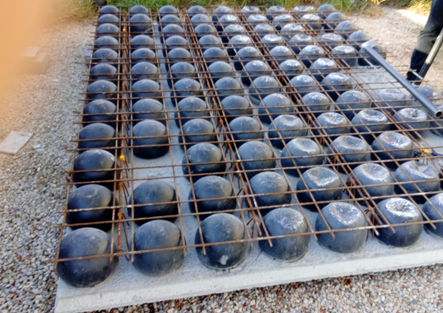
The slab that comprises of plastic void balls in middle which are sandwiched between top and bottom mesh to reduce the dead weight act on the slab
It is a biaxial hollow core slab where the concrete which is not performing any structural function are eliminated lead to reduction in 30% to 50% of its slab weight
Principle:
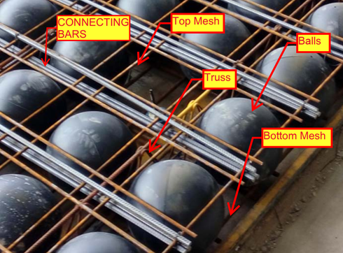
The Hollow plastic balls clamped with the top and bottom reinforcement are placed in the thin concrete of 60mm with max length and width of 10m x 3m to form a precast setup will be done in factory. After that the setup will be installed on site with connecting rods and by pouring concrete
The 35% saving in concrete composition was achieved by the ratio of Plastic ball diameter to the thickness of the slab depth
The reduction in slab weight leads to achieve the Load bearing capacity at a smaller slab thickness result in saving 40 to 50% of material consumption per Floor level.
Materials for Bubble deck slab:
Concrete
Standard with max aggregate size of 20mm
No plasticizers needed for concrete mix
Grade of concrete must be above M30
Reinforcement
Grade Fe-600 strength or high
Top mesh and Bottom Mesh reo of N12 bars max
Truss arrangements for vertical support of balls. Truss height depends on slab depth
Plastic Balls
Hollow sphere Plastic balls made of Polyethylene
Diameter of balls are depends on the Slab Depth. Ball sizes are 180mm, 225mm, 270mm, 315mm and 360mm.
Applications of Bubble deck Slab
Superior Architectural Design
Free choice of shape
Large corbels
Large spans and cantilever
No beam and fewer column results in flexibility
Interior design can be easily being altered.
Advantages:
Structural
Reduce the foundation size since 50% of the dead weight is already reduced by the slab.
Increased Strength due to biaxial Loading.
Longer spans are supported since no bean is required.
Column count can be reduced.
Excavation required less work.
Conduits and openings for service ducts can be easily incorporate in factory.
Construction
Less equipment is required due to light in weight.
Less work on Site construction.
Shuttering work and its Dismantling is not required since the 60mm concrete biscuit will act as shutter.
Construction hours and time taken is very less compare to conventional Slab
Engineering
High resistance against explosion due to biaxial flat slab system.
High Resistance to earthquake due to slab acts as elastic vertical structure.
User friendly to Post tensioning if running through slab.
Environment
CO2 emission due to concrete manufacturing quantity are reduced
Less material consumption
Less energy consumption
Less wood as no horizontal scaffolding
Economy
Sustainable for easy installation
Made to measure and saving material
Fast Implementation and construction
Reduction in Transportation Loading cost.
No shuttering and its cost needed
Disadvantage
Deflection will less higher than the Conventional Slab
Load carrying Capacity is lesser than the Conventional slab
Skilled labour required
Shear Load design consideration and its factor near the column area to slab care is required
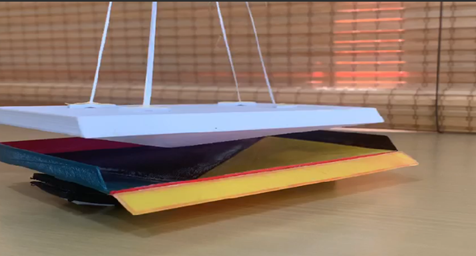
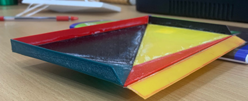
Today we are going to show the miniature Prototype we done on the precast panel and its mould using a 3d printing device.
By preparing miniature we have come across the difficulties and problem that happen during the realistic bound assembly of sheet metal joining for mould and removal of Panel from the Mould setup after the panel casting work completed.
In this case study we will show how the panel removed from the mould set after casting completed by miniature prototype setup
Why Mould needed for this Panel
Normally for rectangular liner profile precast tilt-up panel construction the casting bed with side shutteringwill be used.
Material: Shuttering will be done either in timer or Aluminium Frame
The panel profile faces are sloped or nonlinear and in order to maintain accurate panel profile we need to prepare a separate mould to cast the panel as required.
Material: Mould profile will be done either in Steel Sheet (3mm) or Plate (8mm)
Why Miniature Prototype creation
The main theme of creating a miniature Prototype is by scaling the real time object to check the difficulties and issues that might happen during the process of preparing the Mould and casting the panel with it. By doing this we will be aware where the issue arises and how it can be fixed, so that the cost and time incurred during the real time casting will be resolved.
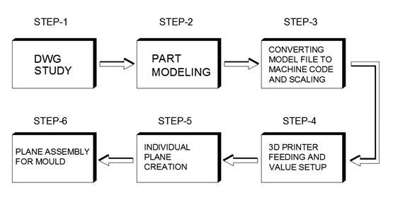
Process of creating Miniature Prototype Creation
Inference
During the process of lifting the panel from the mould, the inner facing splay edges of panel will lead the panel to stop lift from the mould. To overcome this issue one of the inclined splay faces had to be adjustable one (non-permanent fixing) So that after the curing of panel the Mould face will be dismantles to lift the panel from the Mould.
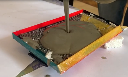
Please see the below Miniature Prototype video of lifting the panel from the Mould after casting done.
The panel has been poured in the Mould Miniature Prototype using Concrete cement with Miniature Reinforcement setup to check further if the panel is all good during the process of casting the panel and the extraction panel from the Mould after the Concrete are cured.
Special thanks to Parthee and Marimuthu for supporting during the Panel Miniature Casting. Thanks to Anandkumar for supporting in Miniature Mould assembly .Thanks to Ben for Supporting in content creation and blogging. Thanks to Koshy , Venkat for providing knowledge towards this idea and help to bring as reality