


COMPLEXITIES FACED DURING MODELLING
We listed and explained some complexities occurred during the modelling, and how it carried out to solve the problems were shown below;
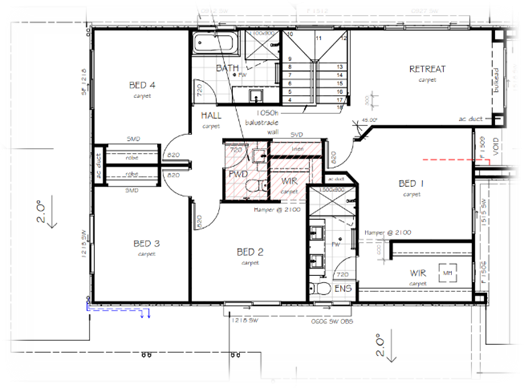
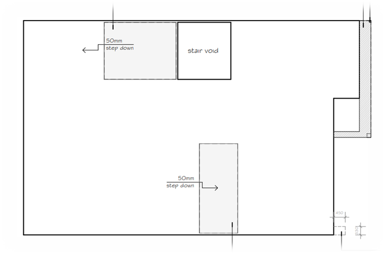
FLOOR JOIST IN WET AREA
The Consultant drawing shows Recess from (50-75mm) of floor for wet Area.

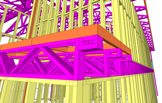
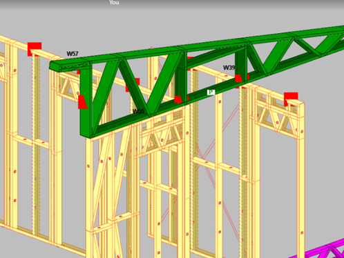
LOWER ROOF TRUSS
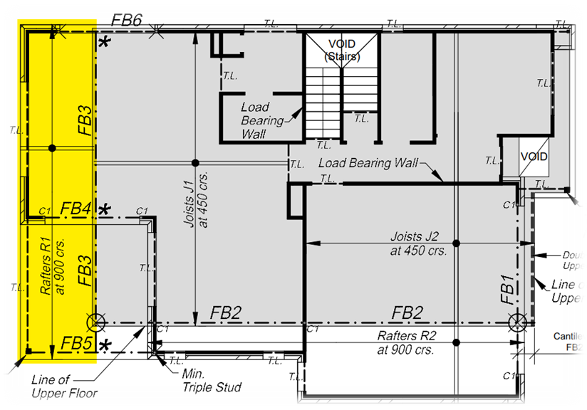
LOAD PATH ON TRUSS TO WALL
Trusses should have proper bearings with walls to carry the load flow from the Roof to the ground. If the load bearings are not applied ,the truss will not be engineered.

MODIFICATION OF TRUSS IN A/C UNIT

The Project Info:
Project Name – Lot 38 (no. 25) Hillsea Court
Building type – Residential Building
Storey – Two-Storey
Site area – 338m2
Roof type – Hip Roof with Fully covered
Our Scope of work in Light Gauge Steel:
Floor Joists, Roof Trusses.
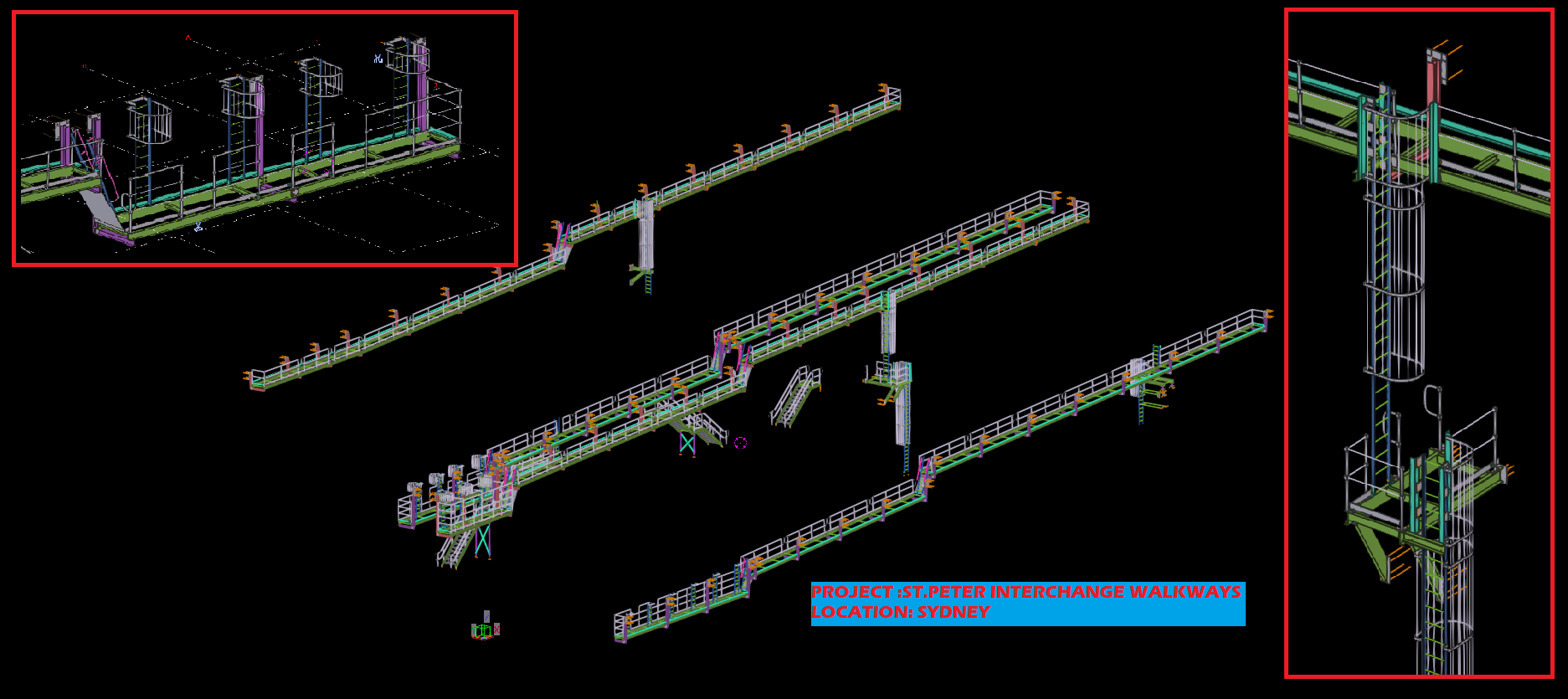
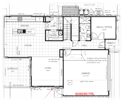
Perspective view of the Project from given Consultant Drawing:

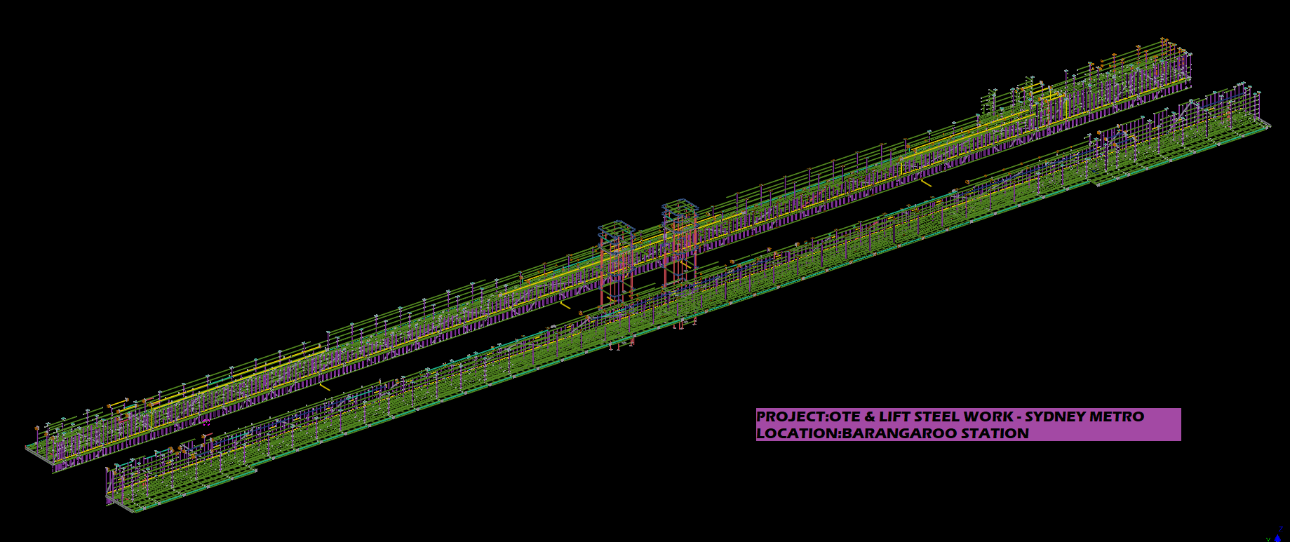
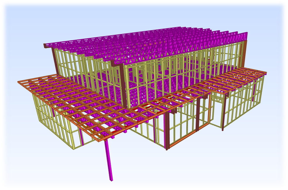
Perspective view of the Project in LGS Framing
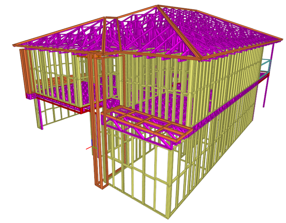
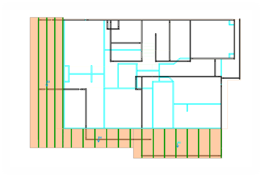
Perspective view of the Floor Joist in LGS Framing

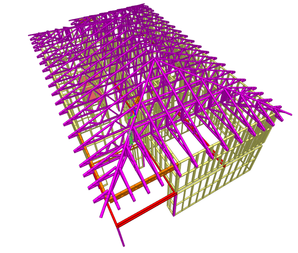
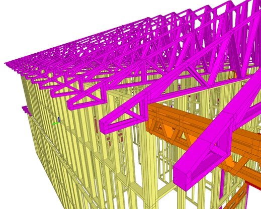
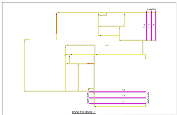
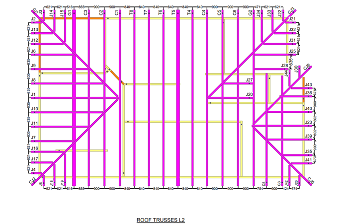
Hip Roof Trusses in LGS Framing

Additional truss details
Based on the Roof pitch and consultant drawing details the Box soffit was created for roof truss & Floor Joist. Refer the below snap.
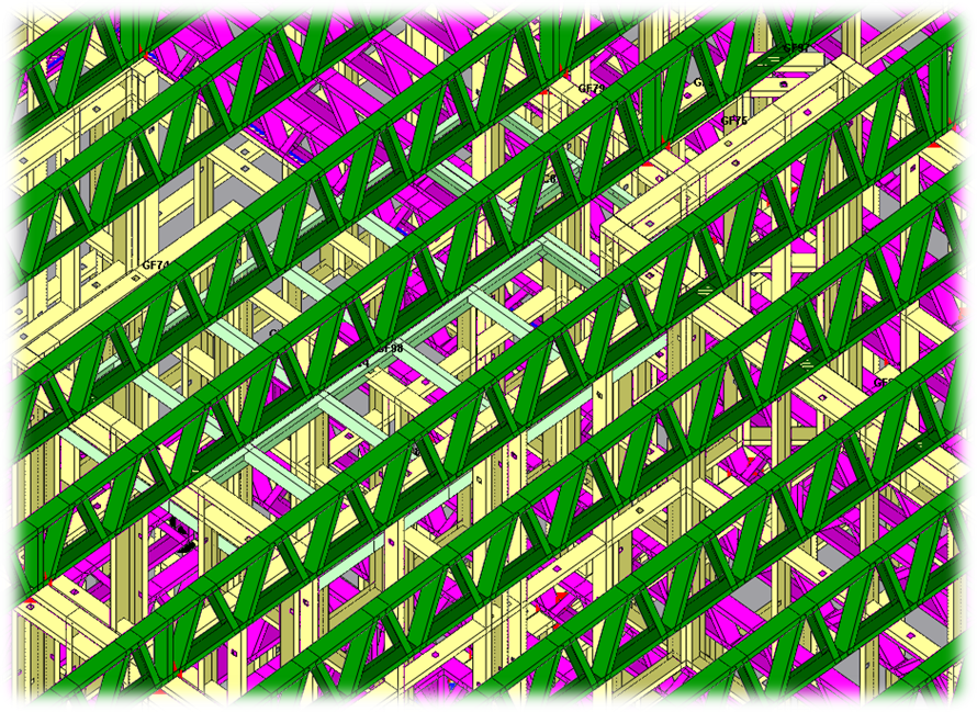
Based on the structural steel Height, cut was provided in Floor Joist. A typical section view was mentioned below.
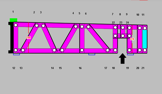
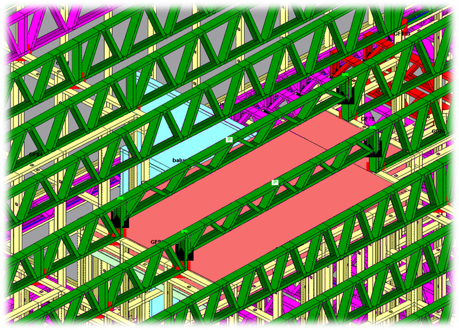
For a/c duct, a cavity was provided in Roof truss(Web). A typical section was mentioned below
Final Layout and output Files:
The following things are get covered in Layout file.
Flooring system details.
Roofing system details.
The following things are get covered in Output Files.
At scale, efficient systems of communication and coordination are required in order to efficiently prosecute projects. These systems will likely be of immense value to yourself, and your clients. Consider the following example:
Our critical path sits within the ABCD building, I have run a target date commencing 29/6/22.
Is this possible for the ABCD given the attached review?
What further do you need from us to mitigate any time frames lost?
Can we get ahead on the procurement of the Steel while we look to focus on getting the SD’s to IFC this week with Tek1?
Email received for the ABCD Building.
The critical question: what are the hold-ups for the project?
Likely our client, has no idea, let alone the builder/developer (a large one). Projects are held up in the weeds. The folks at the top of the supply chain need to make resource allocation decisions. Right now, they’re doing so, effectively blind. Or they have to send out emails like this one.
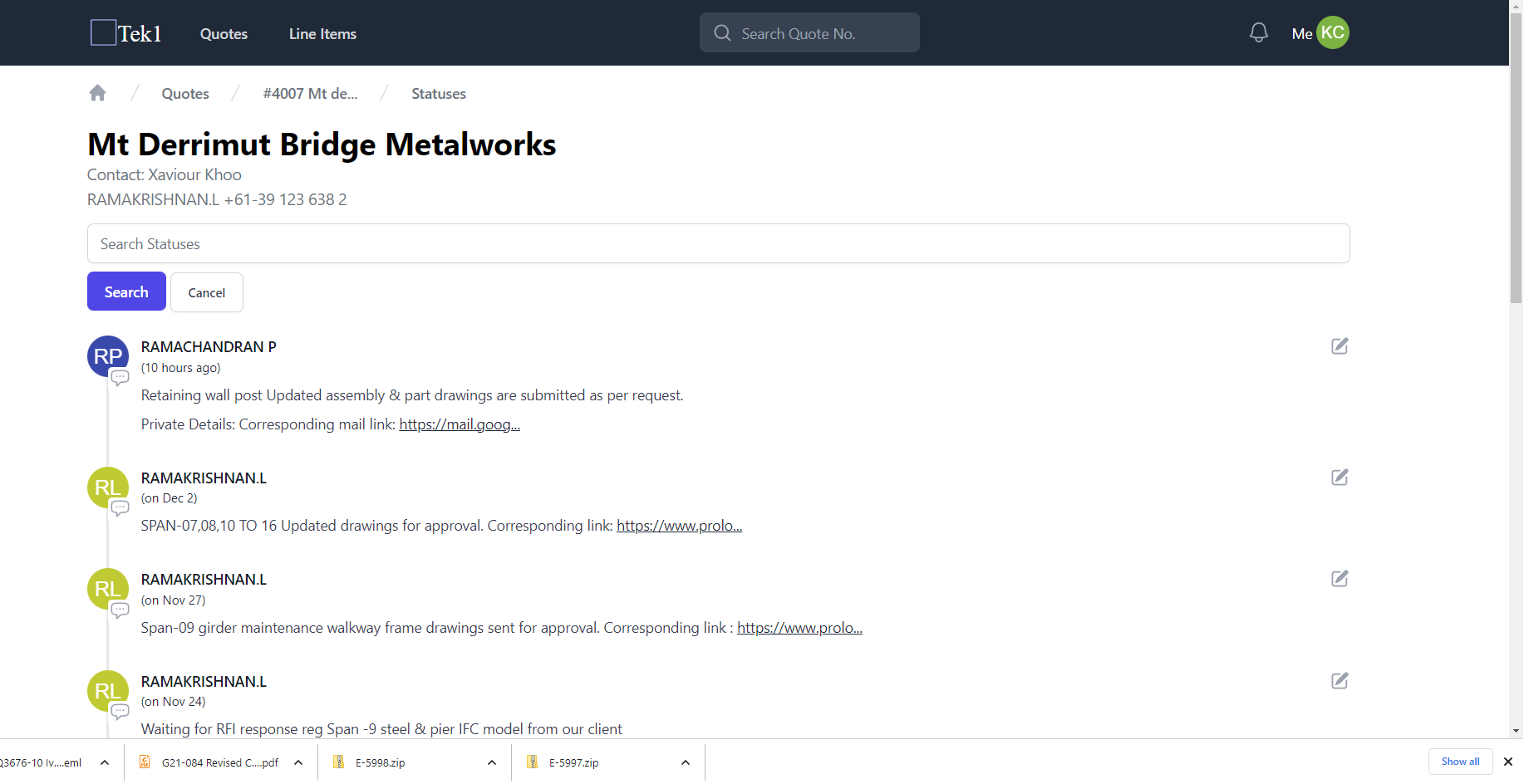
Would anyone remember, what the specific hold up for the project was a few months ago? It’s very hard to remember. And it’s hard to dig it out of the 100s of emails you would have received over that time period. But if you have built up a timeline, it is relatively easy to see what’s happened. All I had to do was to check out our status reports:

As you can see: the project has been in limbo since the 20th of April. It’s self evident. If you didn’t have a timeline, you’d have to bury your head in 100s of emails to retrace your footsteps. We’ve been waiting for this review for three weeks. That’s roughly three weeks ago.
As usual, the reviewers are holding up the show. Except now, given everything is tracked, it’s very hard for them to conceal their inefficacy. Then there were the delays due to: (i) asking RFIs, and (ii) waiting on those answers. (The RFIs are usually asked in the first place, due to the poor quality drawings that are received). The price of inefficient designers (architects / engineers) is monumental. Add poor coordination into the mix, as well as ballooning material / labour costs, and that spells a perfect storm for builders.
Building up a simple status timeline massively improves transparency, improves communication with your client – and all this for very little cost.