Month: June 2022

  • Why Assembly Label cannot be the same in Shop Drawings and Structural Engineer’s document?

    Client query: Some of our clients ask us why the Labels for assemblies varies in our shop drawings from the labels mentioned in the Structural Engineer’s documents.

    This Blog explains why this can’t be done.

    Comparision with Structural documents:

    Normally, In Structural Engineer’s documents the same label will be given to the members of same profile used in different instances irrespective of their other properties such as change in geometry, connection members welded to the assembly, etc.,

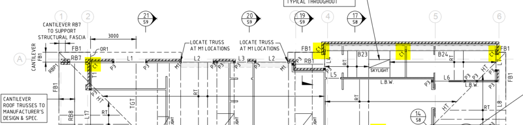
    For Example: In below image, the highlighted column C1 – SHS 89*6 is used in multiple instances.

    Snap From Structural engineer document

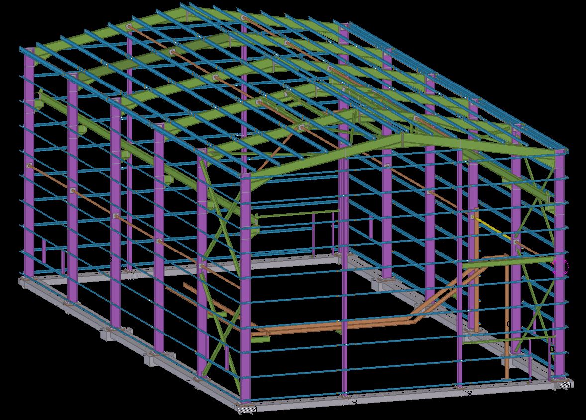
    Working with Tekla Structure:

    In general, This method cannot be followed while detailing because each member (even if the profile is same) will have it’s own shop drawing depending upon the change in any of its properties such as geometry, material, finish, connection members welded to the assembly & so on.

    Refer below snap for clarity.

    Snap From Tek-1 GA Drawing

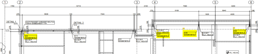
    In summary, although we have used the same profile for the column C1 as mentioned in structural documents, due to the change in connecting members welded to the column and change in geometry we have provided different labels in the GA drawings.

  • How to Quote For Jobs

    The Golden Rule: Be very clear and specific about what you are quoting for. e.g. I am only going to work on the following (insert specific details), and everything else is excluded.

    Why is this important?

    • Clarity: Your client will know exactly what you are quoting for. Use diagrams, and present documentation to improve clarity. The last thing you want is your client to call you and say: “what about the stairs?”. It will not do for you to turn around and say: “oops, I meant I was only quoting for structural steel”. Clarity eliminates these types of problems.
    • Limited Liability: Do not write a blank cheque for clients. If you return a quote to: “build a house” then this quote is essentially open ended. They might get the wrong ideas in your their head: how large is the house? How much material? How long will it take? How will it be built? What if the client keeps changing the design? How much time are you willing to devote to keep making those changes? Even worse, what if you are forced to keep redesigning a house according to the caprice of a third party – whom you have no control? i.e if an engineer and architect keep changing their designs, then you may be destroying your margins and taking a steep loss, as well as massively increasing the risks something goes wrong. Always limit your costs, in some way. Make this clear to clients.

    Variations:

    • Watch out for design and build jobs: As alluded to above, the design process is fraught with difficulties. Too much back and forth with engineers. Limit this liability in some way: e.g. perhaps by hours worked on a project.
    • How we quote: we quote to a specific set of drawings. Invariable, these drawings change due to the discovery of problems as the building/structure progresses. Whenever something changes: that adds considerable risk to the project, cost, and delays. These costs need to be recorded and passed up the chain. No longer can engineers, architects and builders make changes, willy-nilly, and pass on risk, expenses to sub-contractors with equanimity.

    Specific Examples of Quoting:

    1. Limit scope to a drawing number.
    2. Limit scope to a particular drawing revision.
    3. Limit scope to the number of beams etc.
    4. Limit scope to grid lines.
    5. Limit scope to quantities.
    6. Limit scope by listing exactly what you are building.
    7. And exclude everything else.
    8. Show diagrams so that your quotes are crystal clear. This gives confidence to the quotee – they will know that your quote is well considered, and probably accurate.

    Here are some examples, of how we quote.

    Northern Retaining Wall

    Detailing structural beams, connections details, according to the following scope:

    Drawing 1: Type – T1 250UC90 HDG QTY: 299

    Drawing 2: Type – T2-L 250PFC HDG QTY: 1

    Drawing 4: Type – T2-R 250PFC HDG QTY: 1

    Drawing 5: Type – T7 250PFC HDG QTY: 26

    Drawing 6: Type – T8 250PFC HDG QTY: 1

    EPH – Station Platform Northern Retaining Wall

    Drawing 7: UC 150 x 37.2 post with base plate. QTY: 58

    Drawing 8: PFC 200 with Base Plate. QTY: 4

    Everything else is explicitly excluded. Changes might incur charges via variations. Fully documentation will be provided.


    Highlight Items on a Drawing

    • highlight scoped items in a drawing.
    • Add a note showing what is in scope. Why? Sometimes it is not immediately apparent what is being scoped in and out – especially if we are using a drawing with someone else’s markup. Do not simply highlight – we need the note as well. The note should say:
      • “The highlighted elements are in scope. If it is not highlighted, then it is OUT of scope”.

    Here is an example:


    Highlight Scopes + include a note
    Highlight Scopes + include a note


  • A detailers’ guide to sheet metal bending

    This blog illustrates how to provide the dimension detail in an efficient way for sheet metal bending using Tekla Structure. For bending of sheet metal, we need to provide add-on information in Pdf drawings and dxf files for calrity of fabricator.

    By default the Tekla Structures can generate drawing with bend lines. But it is not sufficient for the fabricator, until he knows which side to bend the sheet. This can be achived using the plugin “DSTV TO DXF CONVERTER” available on Tekla Warehouse.
    (Note: Always check if the drawings are created in front view for high quality output.). See below image for clarity

    Snap without bending information on pdf drawings
    Snap with bending information on pdf drawings

    Steps to show bending lines:
    When a DXF file is exported using Tekla it shows reference line. In order to add the bending lines we use the tool “DSTV TO DXF CONVERTER“.In this tool, there is an option to provide a bending line in a different layer on the dxf file. The output dxf files contain information in which direction the sheet has to be bent. This information can be used by the detailer and fabricator for quality output. See below image for clarity

    DSTV TO DXF CONVERTER TOOL
    Snap without Bending information on dxf files
    Snap with Bending information on dxf files

  • HOB AND ITS TYPES

    HOB
    Hob is projection or recess on the top of slab, which is made up of concreate or sometimes precast. It will act as a base or foot for the precast panels and balustrade which are to be placed above the actual SSL (Structural surface level) and a locating guide sometimes with weather proof.

    HOB TYPES

    1. Weather proof Or Stepped Hob:
          This type of hob has projection from slab SSL, which is used to separate inside (living spaces) and outside (balconies and wet areas) of the building to resist water to enter the building. It has recess at the outside of the building on top of the hob, which means top face has step along the outside of building. Refer Section A-A for weather proof hob.

    2. Flat hob:
         It is also projection type hob, but top face is in full width flat without step. Usually, it will locate between either inside-inside or outside-outside area. Refer Section B-B for flat hob.

    3. Recess hob:
      
      It is further back from SSL or ditch or recess on slab. It will also act as weather proof. This hob needs some gap clearance on the higher side to make easily sit precast on it. Refer Section C-C for recess hob.

    4. Balcony hob:
         
    Balcony hob also be the projection type; it is used to outside of the building in outermost wall to resist spill of water or use as balustrade. Balustrade purpose hob have considerably higher than the all-other hobs. Refer Section D-D Balcony hob.

    5. Model hob plan drawing: