Add “set XS_PLUGIN_DEVELOPER_MODE=true” to the teklastructures.ini file and open Tekla Structures. – Trimble Documentation
In order to add the flag above, you need to locate the ‘teklastructures.ini’ file: on my PC: it is here: `D:\Program Files\Tekla Structures\2019.1\nt\bin` (refer to the above URL) – it might be in the C: drive on your computer.
As you can see they are basically .bat files. Which means you can use “MS-DOS Batch File Language” or batch commands in there. The MSFT documentation suggests you can also use PowerShell (https://learn.microsoft.com/en-us/powershell/scripting/overview?view=powershell-7.4) script commands.
Here is the post build event I used:
The Tekla documentation is confused about where to paste the DLL – in some cases they say the ‘plugins’ folder, but in others, it is the ‘extensions’ folder. Yet elsewhere, different Tekla versions have different places where you can paste it. In my case, I have focused on the “extensions” directory.
Warning: If you paste it into multiple locations, you may find that you cannot hit break points! The above link suggests the files should be copied into the .environments/common/extensions folder. I am taking that to mean, in actuality: the `Environments/common/extensions` folder. I am not pasting it into the `plugins` folder, but have opted for the `extensions` folder.
If you want to use the plugins folder, follow these instructions: The dll containing the plug-in has to be copied into: \<Tekla Structures installation folder>\<version>\nt\bin\plugins. A sub-folder could also be created to store the dll. In my case, the plugin files are located here: D:\Program Files\Tekla Structures\2019.1\nt\bin\plugins\TestWPFBeamPlugin
Setting up a macro:
Run the UI macro (Reloadplugins.cs) in the Applications & Components catalog on the side pane. We must set it up. In my system, the location is at the following:
This narrative unfolds the profound impact a meticulous steel modeller can have on structural design.
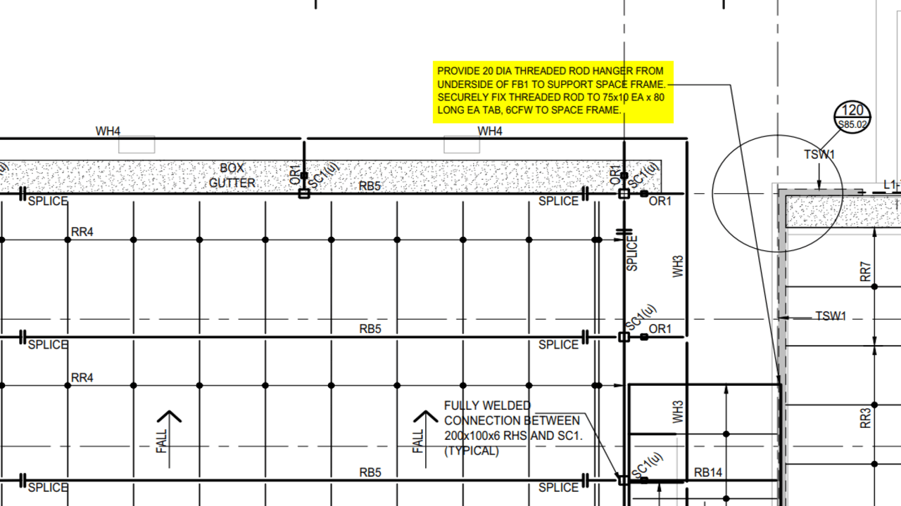
In a residential villa, a canopy has been included at the entry. To support the canopy on the ground floor, as per the design, a 20Ø threaded rod was initially intended to extend from the floor beam to pick up the canopy frame.
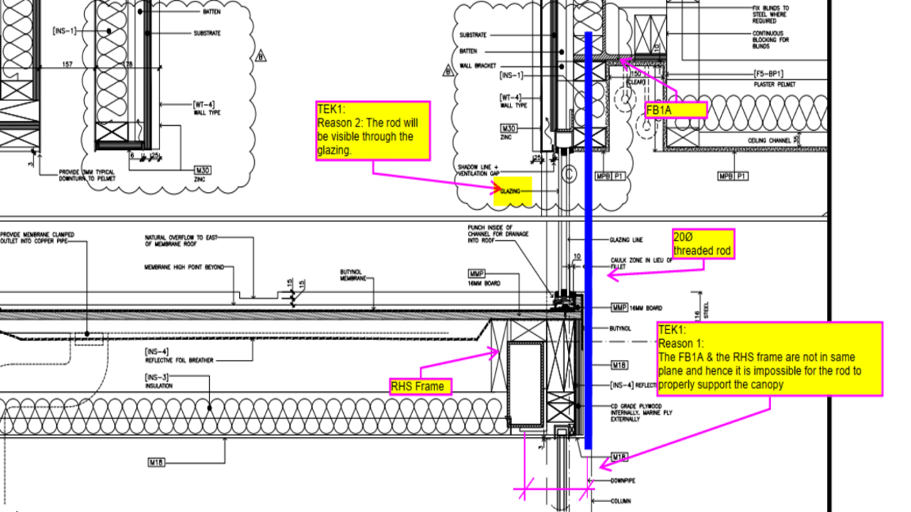
However, during the modelling process, two issues were identified.
First, the rod would be visible through a glass window, impacting the building’s aesthetics.
Second, a misalignment between the canopy frame and the floor beam made it impossible for the rod to properly support the canopy.
To address these challenges, a Request for Information (RFI) was initiated. The goal was to find innovative solutions that would not only maintain the intended design but also overcome the unexpected hurdles.
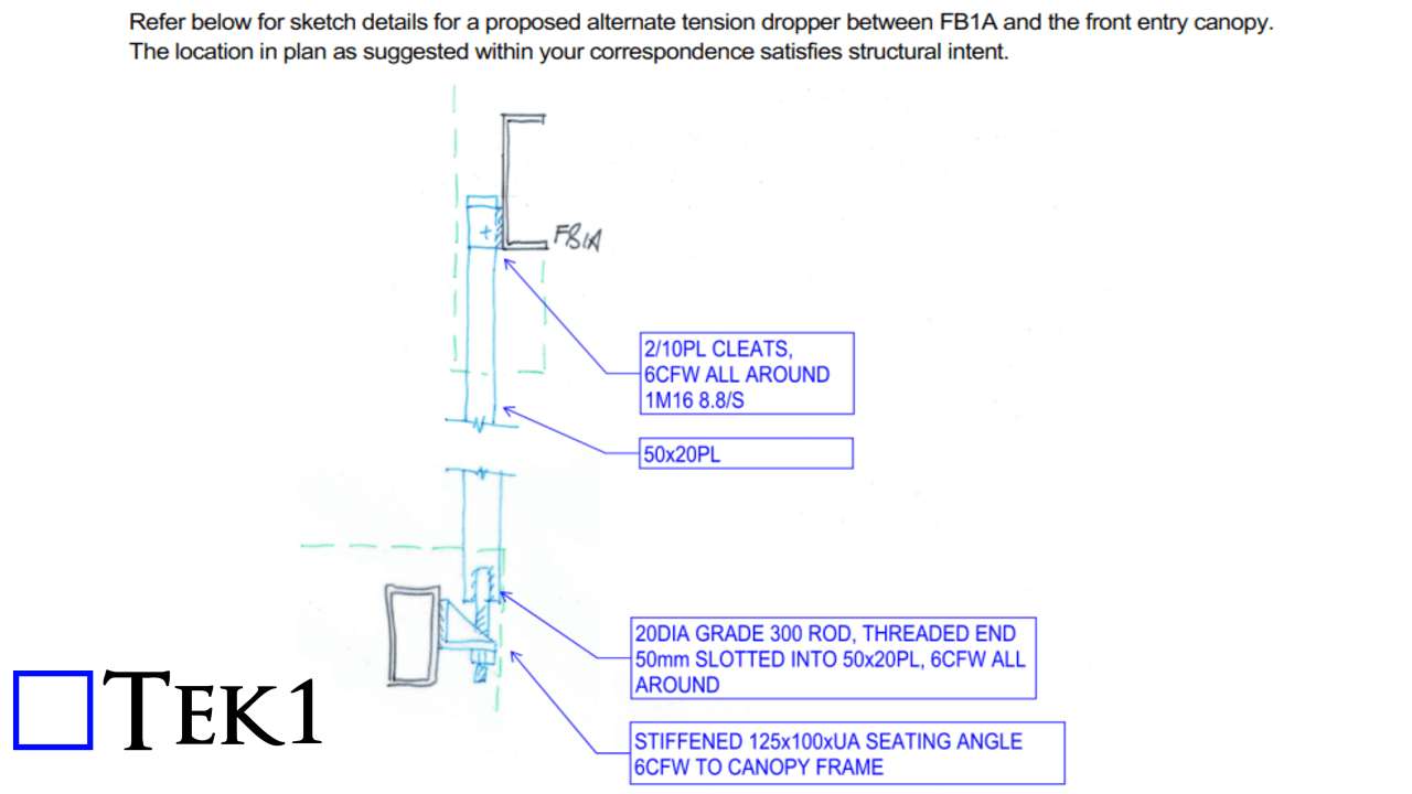
In a dynamic exchange of ideas, acknowledging the misalignment challenge, a new EA wa. This adjustment aimed to harmonize the canopy frame with the floor beam, ensuring a seamless integration of the threaded rod and the overall structural elements.
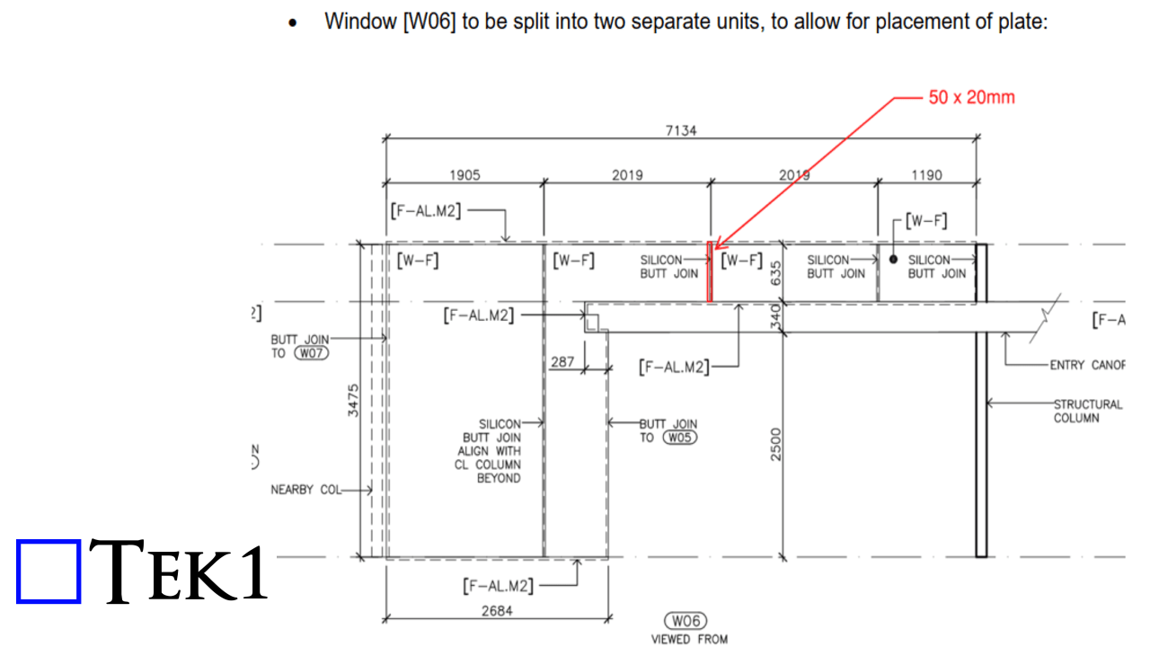
Additionally, the window was split into two sections, covering the rod with a silicon butt joint to maintain the building’s visual appeal.
In the face of unexpected design challenges, the collaborative process of raising an RFI and responding with creative solutions led to a harmonious blend of form and function.