Month: December 2024

  • TRAFFICE BARRIER RAILING

    TRAFFICE BARRIER RAILING

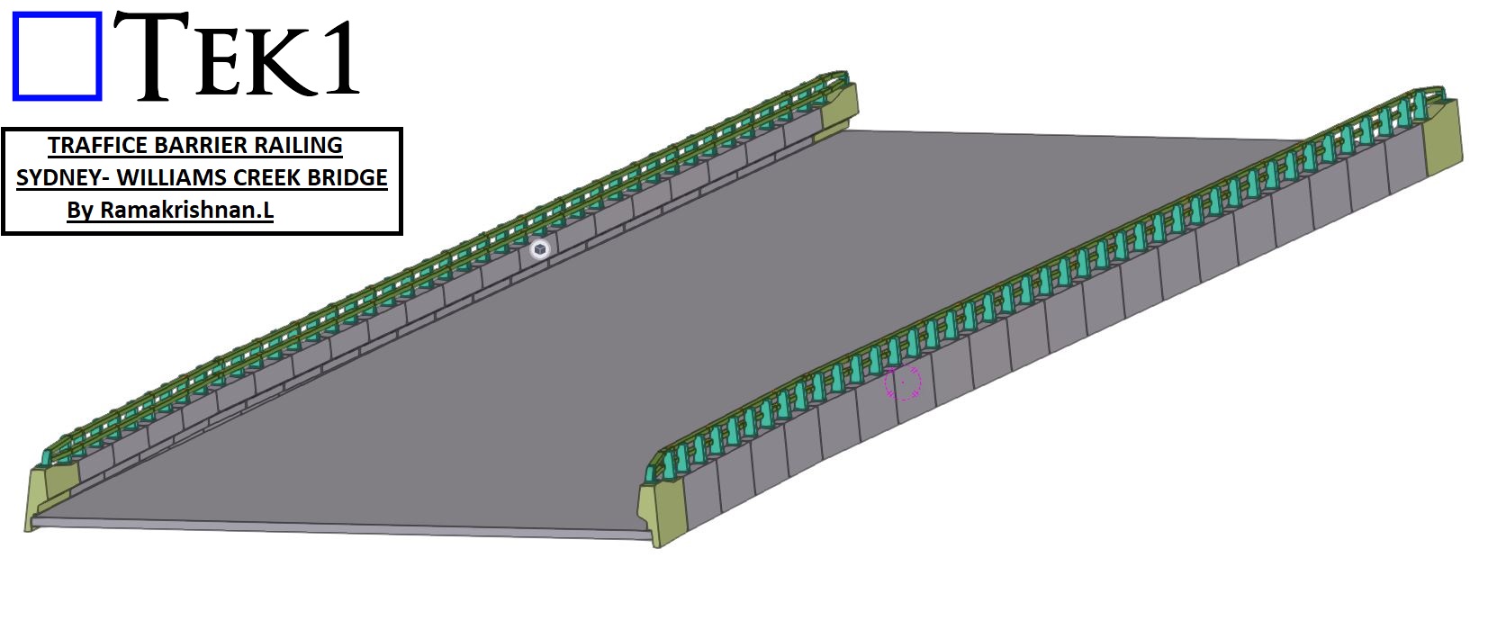
    TEK1 recently completed the project TRAFFICE BARRIER RAILING project for the William Creek Bridge in Sydney. .

    Project Overview

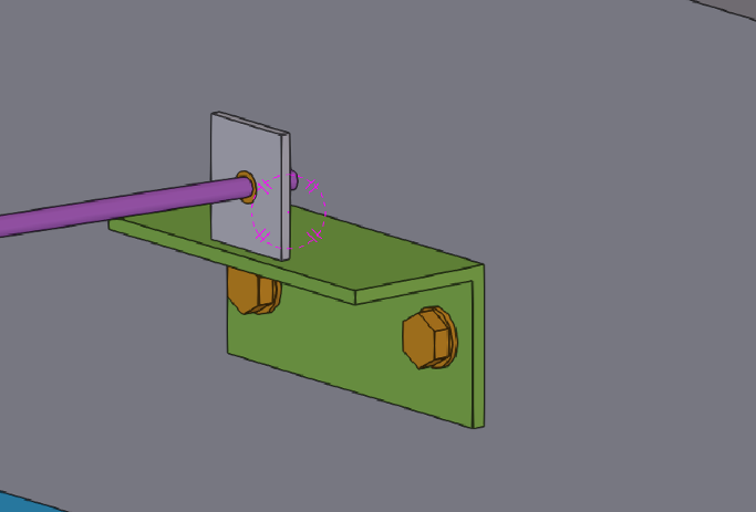
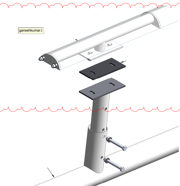
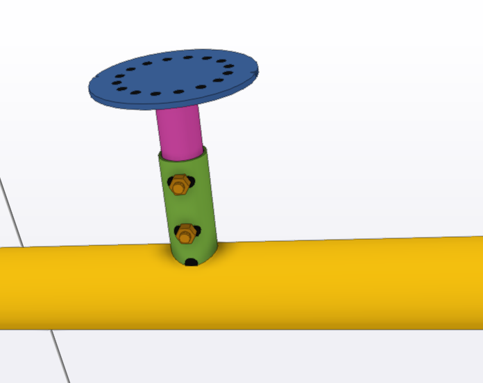
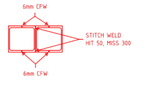
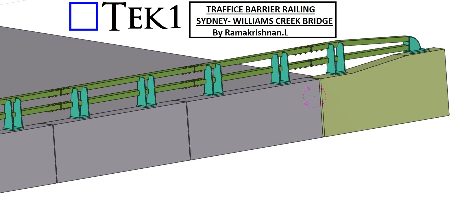
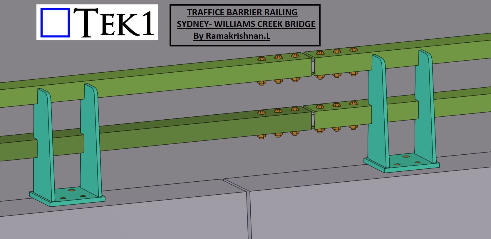
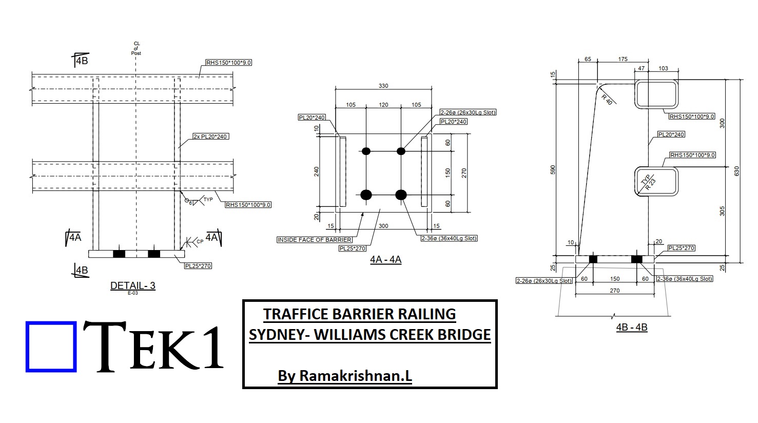
    The primary focus of this project was the detailing and coordination of the barrier railing connections with respect to the precast barrier. These connections are integral to ensuring the railing system’s strength, stability, and compliance with safety standards.

    Key Features of the Railing Connections

    • Structural Integrity: The railings are designed to withstand significant impact forces while maintaining their position and alignment.
    • Ease of Installation: Modular detailing allowed for efficient installation on-site, reducing time and labor.
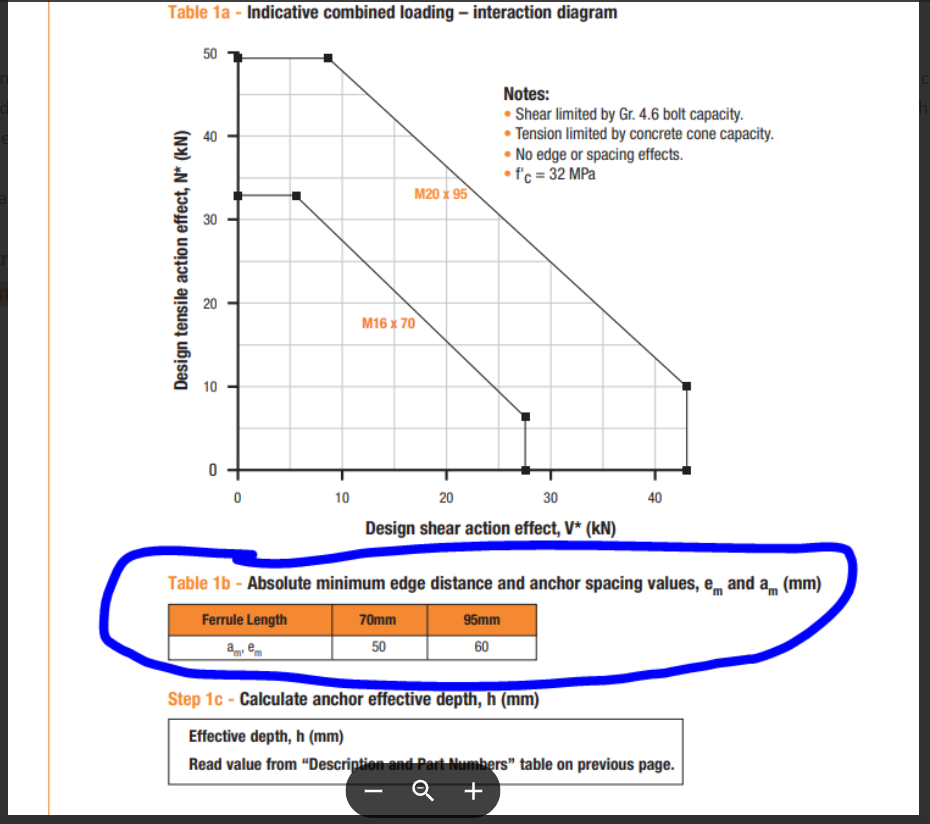
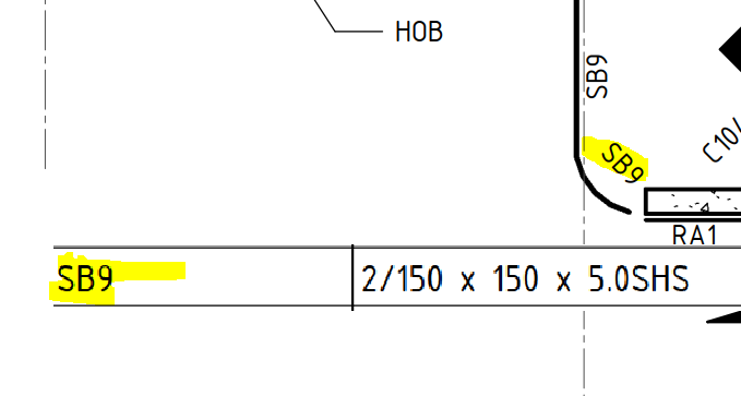
    • Compliance: All railing connections were developed in accordance with Australian standards, ensuring public safety and long-term reliability.

    Conclusion

    TEK1’s work on the William Creek Bridge reflects our commitment to enhancing public infrastructure through precision detailing. By focusing on both safety and functionality, we’ve delivered a barrier railing system that meets the highest standards.

    Stay tuned for more updates as we continue to contribute to impactful projects that make a difference in our communities.

  • Project :Audi Centre – Myaree

    Project :Audi Centre – Myaree

    5 Carr Place, Myaree, WA 6154

    TEK1 recently completed the project Audi Centre Myaree a Audi Car showroom in Western Australia. This impressive structure is a 100-tonne steel building, featuring two floors and a main roof, exemplifying modern design and engineering precision.

    Scope of Work: Steel and Precast Panels

    Our scope for this project included detailing both steel and precast panels. Managing these two critical elements simultaneously required meticulous coordination and attention to detail. The integration of steel and precast detailing enabled us to ensure accurate connections between the two systems, delivering a seamless result.

    Overcoming Challenges with Precision

    Handling both steel and precast in a single project can often lead to coordination challenges. However, thanks to TEK1’s skilled team and advanced detailing processes, we completed the project without any hitches. Our approach ensured that all connections were detailed precisely, aligning perfectly with the design and site requirements.

    Precast Model

    Conclusion: A Milestone in Steel Detailing

    The Audi Centre Myaree stands as a testament to TEK1’s ability to manage complex projects involving multiple structural elements. By combining expertise, coordination, and a commitment to excellence, we delivered a showroom that reflects the high standards of the Audi brand.

    At TEK1, we continue to set benchmarks in steel and precast detailing, ensuring that every project we undertake is marked by efficiency, accuracy, and success.

  • Purlin Bridging support with concrete wall

    Purlin Bridging support with concrete wall


    Bridging is commonly used to tie purlins together, and while structural engineers specify the type of bridging in the design, it’s up to the detailer to adapt it based on the purlin arrangement. In this blog, I’ll share how we handled a bridging connection scenario involving a concrete wall.

    If you want to know ,more about bridigng. See our previous videos


    Typically, bridging is tied to steel beams at one end. However, for this project, the client requested that the bridging be tied to a concrete wall instead, as there was no direct steel connection point available.


    To meet the client’s request, we designed an additional support system:
    Equal Angle Support: An equal angle was anchored to the concrete wall using chemset bolts.

    Welded Plate: A plate was welded on top of the angle to serve as the connection point for the bridging.


    Bridging connections require careful consideration, especially when working with non-steel elements like concrete walls.

  • Staff Memo – Webmail Login

    Please use the following link to login to your tek1 engineering services mail: https://gvam1290.siteground.biz/webmail/mail/

  • Absolute minimum Anchor Spacing

    Please note that the spacing and edge distances given in the ferrule tables is for design purposes only and not a minimum for actual installation. That is the dimensions given are for each insert to achieve 100% capacity. They can be placed closer. It just means their combined capacity will be reduced. The same is for drilled and epoxied bars.

  • EMU IN THE SKY:Branches

    EMU IN THE SKY:Branches

    Continuing from our previous blog on the EMU IN THE SKY project, this post delves into the challenges and solutions for positioning the branches into the globe structure.

    Challenges with the Original Design

    The initial structural design, while visually impressive, posed significant challenges during the erection phase. The lack of tolerance in positioning the branches made the process more complicated, increasing the risk of errors and time-consuming adjustments.

    EMU team proposal

    To overcome this, the team introduced:

    Circular Plates with Holes: A circular plate with pre-drilled holes was introduced, allowing for precise alignment of the branches.

    Slotted Holes in the Outer Stub: Slotted holes were added to the outer stub welded to the globe. This innovation offers adjustable positioning, making the assembly process significantly easier and more efficient

    In this method we can place the branches plate in any rotation.

    Why This Design is Feasible

    The updated design not only simplifies the erection process but also reduces the likelihood of rework. The added tolerances ensure that branches can be positioned accurately with minimal effort, saving both time and resources.

    Stay tuned for more updates on the EMU IN THE SKY project as we continue to share insights and innovations from this iconic endeavor.

  • Expert Steel Detailer looks beyond Structural Drawings

    Expert Steel Detailer looks beyond Structural Drawings

    Expert Detailing | Sydeny | Melbourne

    This blog focuses on a crucial aspect of detailing: collaborating with fabricators and understanding steel profiles.

    Structural engineers typically specify steel profiles based on their calculations. However, as detailers, we need to consider two critical factors:

    Product Availability: Is the specified material readily available in the market?

    Fabrication Feasibility: Can the profile be easily fabricated?

    Balancing these factors can save significant time and effort for both fabricators and detailers.

    Real-World Example

    In one case, an engineer specified a curved SHS (Square Hollow Section) beam.

    While this profile met the structural requirements, bending an SHS beam is a challenging process .There are fabrication limitations. Instead, we suggested using two PFCs (Parallel Flange Channels), which are much easier to bend.

    Before making the change, we sought the engineer’s approval, and they confirmed the modification. By doing so:

    • We avoided delays in fabrication.
    • We ensured the project stayed on schedule.

    Why This Matters

    If we had followed the original design without questioning it, the fabricator would have requested changes due to the difficulty of bending an SHS beam. This would have caused delays and disrupted the project timeline.