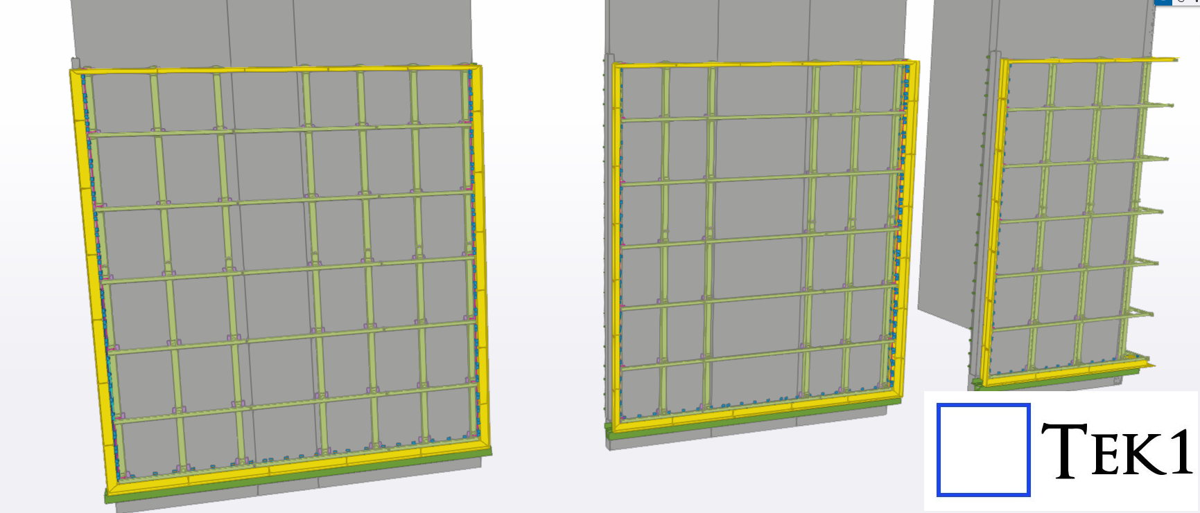
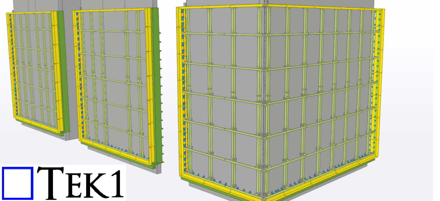
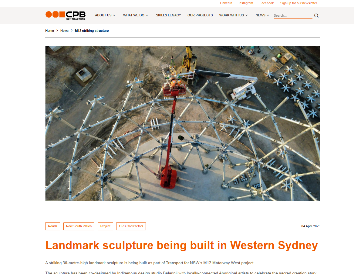
TEK1 recently completed a media wall support project for a prominent organization in Australia. The goal was to provide detailed support steelwork for a large media wall screen — with a unique challenge.
Unlike most projects, we didn’t receive any structural design drawings. Instead, we were given only a concept design, leaving it to TEK1 to determine suitable steel profiles and connection details.
Our team carefully studied the concept and nominated appropriate profiles for each connection based on feasibility, strength, and ease of fabrication. Once the detailing was complete, we submitted it to the structural engineer for review.
The engineer approved our detailing with minimal changes, which helped speed up the process and made things easier for the client. The use of different profile types also optimized the design for practicality and efficiency.
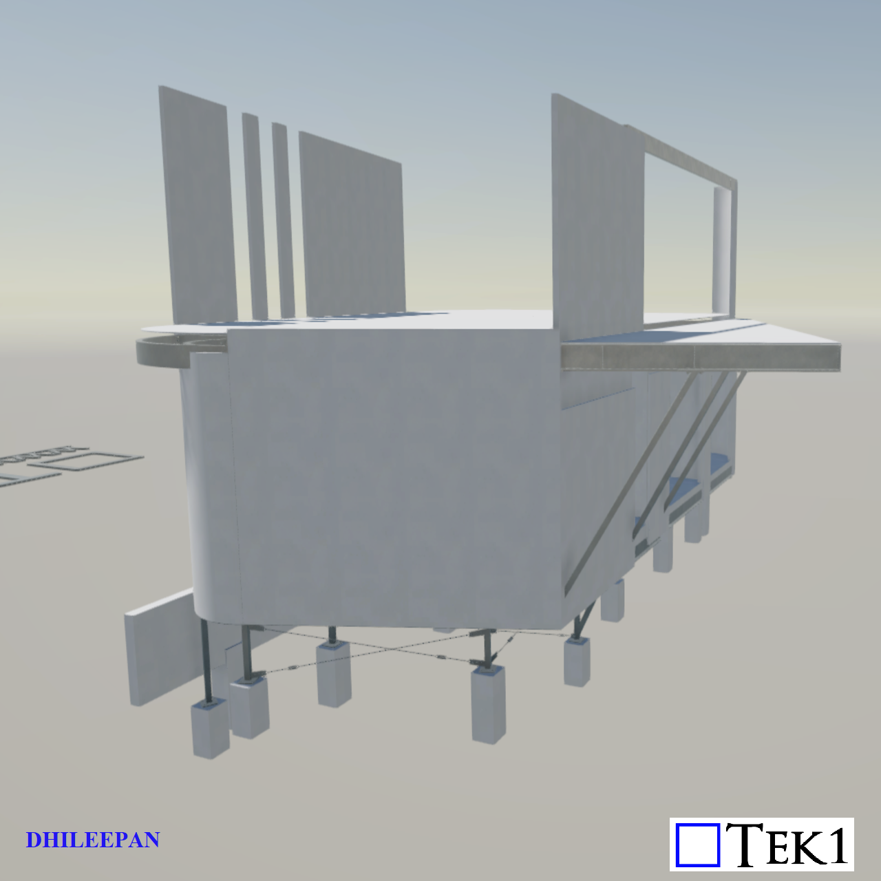
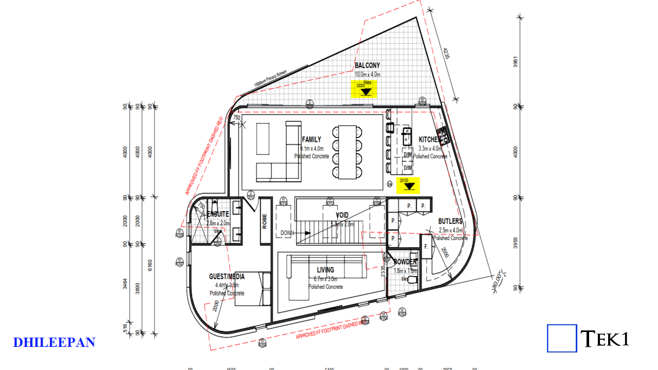
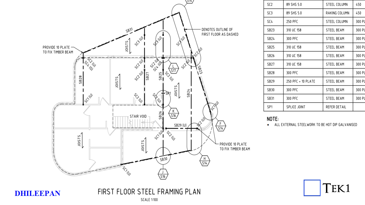
In a residential project nestled in the scenic suburb of Scarborough, Bundeena, a critical coordination issue surfaced during the construction of the first-floor balcony. Originally designed to sit 100mm lower than the internal first-floor level (with the balcony at RL+33.000 and the floor level inside the residence at RL+33.100), the structural drawings, however, did not reflect this intended step-down.
ARCHITECTURAL PLANSTRUCTURAL PLAN
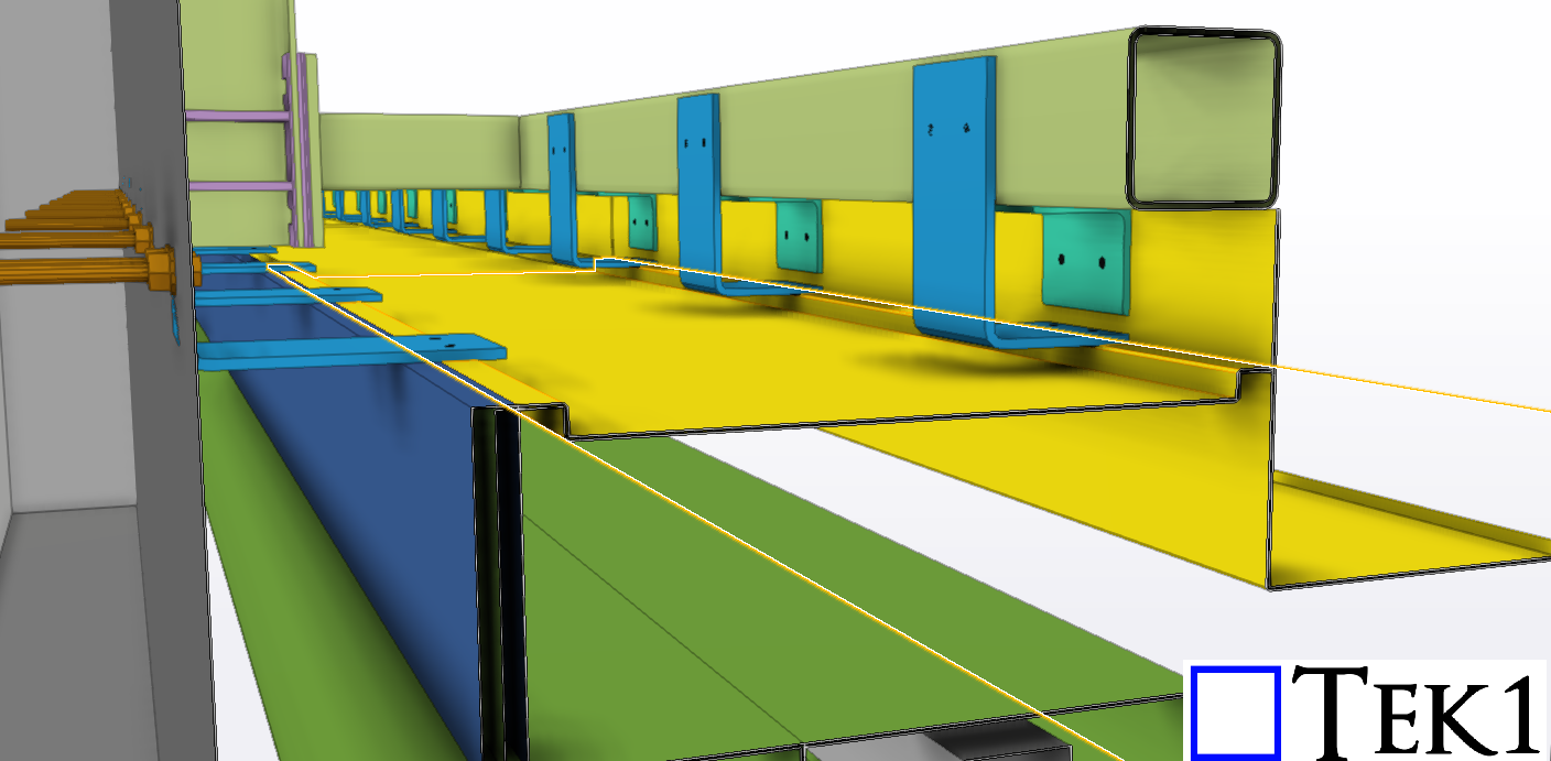
Floor Depth Conflict
Adding to the complexity, the vertical space between the first-floor Finished Floor Level (FFL) and the ground floor Ceiling Level (FCL) was only 300mm, while the structural floor members specified were 327mm deep. This created an unintended exposure of the first-floor framing—both below the ceiling and above the balcony floor.
Level Adjustment Solution
Upon identifying the discrepancy, Tek1 promptly flagged the issue to both the structural engineer and the architect. A collaborative resolution was achieved by adjusting the levels: the internal FFL was raised to RL+33.253 and the balcony FFL to RL+33.153, restoring the 100mm step-down while maintaining all ground floor steel members at their original elevations. The level variation was managed by introducing floor joists of different depths—an efficient solution that avoided reworking the base structure.
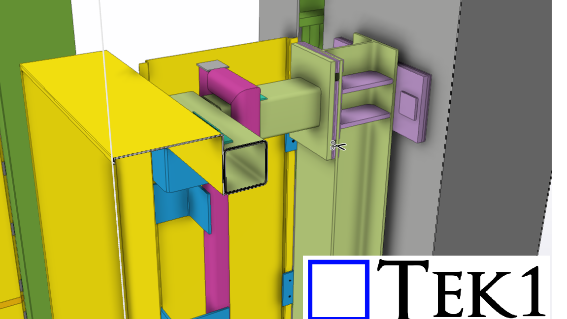
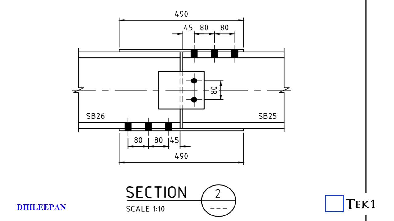
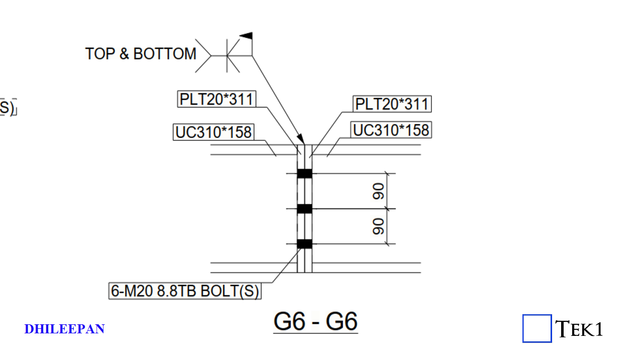
Splice Connection Clash
Another issue surfaced in the form of a splice connection detail provided in the structural drawings. The original design called for splice plates on both the top and bottom flanges of the beam. However, the bottom plate posed a risk of clashing with the ceiling board. Tek1 proactively suggested an alternative splice configuration that avoided interference with the ceiling. This revised detail was reviewed and subsequently approved by the structural engineer.
DESIGN SPLICEPRPOPOSED SPLICE
Conclusion
This case serves as a strong example of how early-stage detection, open communication, and thoughtful coordination between teams can lead to efficient, buildable solutions—ensuring design intent is met without compromising on functionality or aesthetics.