This video explains selecting in Tekla
Author: admin
-
Curved Beams
This tutorial deals with how to create curved beams with 3 point click and polybeams
-
Tekla Training
Lesson 25- Use Appropriate filters
-
Cuts and Fits
In this video we will cover Cuts and fits. Please review this video before attending
Exercise files to create some cuts https://www.dropbox.com/sh/01828m6bh48y528/AACZz0XB_skUl8Mz5k0PWZEva?dl=0
-
Tekla Introduction
Following items will be covered in the introduction
Introduction
Panning and Zooming
Switching to Normal View
Creating ViewsDownload dropbox model https://www.dropbox.com/s/a2vztcbxc3buadb/USER-INTERFACE.zip?dl=0
-
How does Tek1 do Bubble Deck? Our Shop Drawing Processes
The best way is via demonstration. Please see some of the video demos we have put together. It is not by accident that our drawings come to you quickly. There are 10 distinct stages. We will upload the rest of the stages as we get and when we get an opportunity.
The full list is here:
Many commands do not have any video documentation attached. Some of the ones we have are documented below:
We have updated our Insert Panel Lifters command:
Dimension Tooling
1 – Layout Commands
enter help info here
2 – Shop Drawing preparation
3 – Bill of Materials
4 – Dimension Panels
enter help info here
Insert Blocks
enter help info here.
Utilities
-
NCDXF Files and & CSK Bolt Holes (in Tamil)
NCDXF Files and & CSK Bolt Holes (in Tamil) from Tek1 on Vimeo.
Hi team, please review the video for CSK bolt holes and NCDXF Files – language is Tamil.
-
Minimum Steel Checks
General Discipline
- Update clients on ETA of drawings. Constantly. Clients love status updates, and learning where their jobs are currently at.
- Update line items when they are ready to be invoiced. If you don’t, how can you invoice your clients? If you don’t invoice, then how do you expect to receive payment for your work?
- Follow up on RFIs that are not answered: push the job forward. Clients are relying on you.
- Changes to a drawing? Please markup the REASONS for changes to a drawing. Use markup links if appropriate. If you don’t do this, clients might be confused as to WHY. Especially applicable if a client instructs a change to be made, but the change was not made as instructed.
Checks Prior to Detailing
- Compare the quoted drawings to the drawings you are detailing from: are there any differences – if there are differences then: (i) send a report to the client noting the differences + (ii) send the mark ups + (iii) send any extra steel required. Add these to the extra billables. If there are not differences, then please send an email to the client saying: there are no differences + add your report. You must always send a report, regardless of whether there are differences or not. Add in your reports here: https://docs.google.com/spreadsheets/d/1zmO_dBpxX-ajwoKL0Z-8lgD33I-gQcv6pVp05iBlQqg/edit?ts=5e4577f6#gid=972410357
- Evaluate Site measure requirements.
- Is Steel Fixing to concrete- Get Concrete site-measured, or sent the concrete drawing for approval. Ask for photographs and site measure
- Is Steel Connecting to Existing Steel?. Do we have to ask for site measure? Or can cut to suit at the site be used. Ask for photographs and site measuure
- Check Autocad file for true dimension using the macro. (CD.lsp)
- Clash check
- Member Nomination Check
- Material Check (Under Guidance)
- Standard Flat bar check (All flat bar grade is 300). for 250 use plates
- Tek1 Bolt Tolerance check. (With Select Bolt Option clicked, Select Parts within components Clicked in)
- Tek1 Bolt Check Report- To pickup bolts Bolted to to only one part. (With Select Bolt Option clicked, Select Parts within components Clicked in)
- Loose Plate check (ie whether there are unintended Loose Plates not welded to beams)
- Purlin Cleat Hole Check.
- Surface finish Check. Some drawing study and instruction from modeler.
- Stifner clearance – 2mm for plates within W beams.
- Root radius Clearance for stiffeners and fitting plates.-25 mm chamfer at the root (New). For Gal Venting (Requirement from DM Group)
- Cleat holes at 70 pitch
- Stanchion bolt center distance check for angle mounted and corner stanchions.
- PLATES AND PARTS WITH SMALL DIM DIFFERENCE (LESS THAN 3MM) WHETHER COULD BE MADE SAME.(from drg creation Check)
- Cleats do not change sides between beam to beam. (Check-in plan view)
- Drawing Creation Check. (Use for Profile check and small length difference of plates and beams)
- Part names are set to reasonable names.
- All webforge Names to Webforge Grating spec.
- Is the grating type checked
- Is the grating direction modeled with a part cut using PLT6*20 cutting at the top and not at the bottom?
- Is the grating part drawing showing the cut in full lines and NOT DOTTED
- Is the grating end view correct and consistent with the plan view – download sample grating drawing.
- Is the grating template used for creating drawing (View orientation is local on Grating template) Check(new)
- All Monowills Names to Monowill Catalogue specification.
- Everything else to reasonable names. Do not name a stanchion as Col. a small outrigger as Beam.
- Check Beam Rotation. (Use macro to check). Also Col Rotation. (Use macro to check)
- Run report on Cols top and Bottom RL – Check the top and bottom RL are same unless there is ta reason to be different.
- Run Report on Beam RLs check Rls are same unless there is a requirement.
- Bolt Check. Run the Bolt Check Macro (newly added in checklist on 14/3/17)
- Number setting – Is the name ticked. Name must be ticked because the bridging list depends on the name to get the bridging Number. At the very least the while numbering bridging Name should be ticked. The main Part must take Assembly Mark. (This is required for beamline Marking) (new)
- Are there Anchor bolts going into masonry wall hollows?. If yes, do you know the block wall set out . downlink for bim model. Image of problem. Download pdf.
- Roof requires support on all edges. Make sure no edge is without support
- Profile marks and part marks appear on part mark
- Shortening is switched on in member drawings. minimum cut 100. (Shankar to change the Tek1 Beams template to this setting in starter model)
Drawing Checks prior to detailing Assy drawings – Checked by generating only – No editing
- Unnecessary Part Nos due to small changes in part size
- Base plate drgs for web forge staunctions. Create base plate drgs of stanchions check hole sizes and then delete the drgs.
- Edge distance check on unedited single part and plate.
- Drawing Creation check to confirm all drgs are created- But No part drgs created for purchased items
- Cleat hole pitch 70 mm by default.
- 60 mm if required due to space constraints.
- 50 mm if required due to space constraints. (M16 only)
- 90 mm Gage for 200 PFC, 200 UB AND 200 UC
- Minimum edge distance default 35 mm.
- If edge distance is a constraint then it can go down to 1.5 bolt dia.
- Bolt group modeling. No individual bolts if it can be modeled as a group.
- bridging bolts are individual
- Purlin and bridging hole pitch. for 150, 200 and 250 and 300 purlins.
- Are we using polybeams for anything? Handrails, curved beams Are there at least 2 views? Plan and Elevation?
- Study roof plan. Locate Gutters, roof Slopes, identify Steps if any in the roof. Mark and put notes on Roof Plan
- Study Slab drawing. See if there are floor coverings. See set down areas, Hobs. Mark on Structural drawings set down, Hobs
- Before making assemblies/assembly drawings check erection feasibility and shipment sizes.
- Switch on orientation marks on assemblies and ga plan for the easy erection.
Assy Drawing Checks
- Running dimensions on holes along the beam
- Running dimension for cleat positions along the beam
- Dimensioning to cleat plate on Assy drg is to bolting face.
- Drawings are right side up. (Not upside down) on Assy drgs.
- Root Radius Clash
- 2 mm Clearance for stiffeners in PFC, UB, an UC
- No projected dimensions. (Fabricator has no means of measuring projected dimensions)
- No dimension which can be used for setting up, or cross-checking
- Are Check dimensions there. (Refer this link).
- Provide iso metric Assy view for complicated assemblies.
- Default weld is 6mm fillet weld. All other welds must be called up in Assy drawings.
Welds should be modeled correctly. We cannot model all welds as 6mm fillet weld. If the drawing calls for 8mm weld, it should be modeled as 8 mm weld. - Brick lintels are usually stitch-weld. Make sure the note is on (New) 13/3/2020
Checks while modeling (Main Modeller)
- Did you read Steel Notes and highlight points to note.
- Check whether rod bracings with D Nuts can be used. If yes RFI the engineer if the engineer has shown other types of bracings.(New)
- Beam rotation check. (All beams rotated to top).
- Curved beams Handle to the outside of the radius. Verify using drawing at the modeling stage.
- Test Assy drgs creation. Drg should come right side up
- For CHS with end cleats. CHS rotation matches with End cleats.
- (Procedure. Set UCS to end cleat front)
- Set CHS rotation degrees to zero. (CHS main part)
- Create Assy drawing and make sure end cleats are not rotated.
- No items modeled as folded plates except for parts which will require folding while manufacturing (Sheet metal only)
- No base plate showing up through walls. or projecting into doorways. (Check-in Arch Plan View)
- Clash Check
- Turn Buckle – Check F dim with Catalog. Example https://www.townleydropforge.com.au/catalogue/stub-stub-turnbuckles/
- Minimum ceiling height for offices, public facilities – is 2700
Grating Checks
- Load bars need support.
- Check maximum span. If the span is more, then additional support is required.
- FRP GRATING
- For FRP grating there is no dominant load bar direction
- For FRP grating support is required for all direction of load bar
- Span cannot exceed the specification in both direction
- Do not mark load bar direction for FRP grating
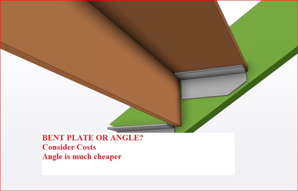
Bent Plate or Angle
When possible use Angles because
Bent plate is more expensive, more time
GA Checks
- Whether Views are taken from the correct side on GA (From where Items are Installed)
- Check RLs on GA while modeling.
- North Mark setting on Cols and model. (Create test Assy drawing). Check out North Mark.
- Steel below Ceiling Check (normally for houses).
- Site Welds must call in GA with detailed.
- Do not connect in GA with dimensions Framing Assemblies which has no relationship with each other.
- Brick Lintel position lines up so that Lower end of brick does not fall out of line with window top (No gap required as bricks are visible)
Single Part Drawing Check (Responsibility of modeler)
- Curved beams – Dimensions are to the outside of the radius.
- Material list length and the dimensioned length matches. – See Example
Modeling checks
- When mullions sits on Hob, RFI whether the mullions should.
- DO NOT MIRROR COLS, BEAMS PLATE. You can mirror points and construction lines(new)
- Bolts to Timber (Only Holes to be provided since bolts are not supplied by fabricator)
- Standard welds are 6mm fillet welds. All other welds must be modelled correctly and called in shop drawings.
- Don’t Draw unnecessary walls and other elements which has no impact with our scope of work.
- At Timber framing connection, Don’t supply the Connection bolts for the Timber Rafters.
Modeling checks for Houses
- Can door open. The sliding door must open without clashing with steel col or base plate.
- Lintels should extend to each side to support brickwork.
- Garage Lintels must support the brick above the door. (Usually with a plate welded under the beam)
- Slab must be modeled correctly prior to starting modeling.
- FFL and SSL should be clearly identified.
- Base plates must either be hidden is walls or under FFL. Top of the bolt should be minimum 30 mm below FFL if not in stud wall (Walking area)
Bridging check
- Check bridging specification in member schedule and notes
- If no bridging is the specified check against Lygsaght catalog
- Put a filter to show only bridging. Make sure there is no gap between bridging to bridging
Facia Purlins
- Angle of the Facia Purlins should be specified to match with Roof Angle
- Facia Purlin Must have a drawing
- Check bracket hole distances. Bracket specifications are different for Facia purlins. Check against Lysaght catalog
Modeling checks for Stairs.
- Is there a site measure required.
- Is the site measure to concrete, have you considered floor covering.
- Ask for the rise and going on the last nosing point. Because landing may have different thickness flooring.
- Are the handrails stainless? The maximum length of the available stainless steel pipe in 6M.
- How is the pipe to pipe connection? Will inline splice be used? Check https://stainlesscablerailing.com/ss-15-splice-inline.html
- Have you checked for125mm ball not passing through pickets and all gaps?
- The maximum number of steps in one flight is 18. Have you checked?
- What is the code to be used? 1428 is public access. 1657 is maintenance. BCA is for residential.
Bolt Checks (New)
- Provide Blue Color for Chemset Bolts – Tolerance 4 mm
- Provide red color for bolts through Galvaniszed members – 4 mm tolerance on Galvanized plates.
- Take a Bolt Summary sheet. Check Bolt sizes
- Put a filter on Galvanized items. Check hole sizes for 2 mm tolerance.
- Special Attention for CSK bolts. Check DXF.
- Do not supply bolts at timber connections. Model holes without bolt option.
Dxf files
- Do not provide centerlines for holes
- Open and check dxf files. Especially plates with CSK holes, since there is a good chance that we can make an error.
Setting out site measure
Minimum 2 Points should be aligned and identfied in drawings and model. One point is not enugh.
How we have used the site measure should be clearly shown in the drawing
Site measure should never be scaled. If the .dwg file turns up with no units, then set the units as appropriate to mm or meters. Never scale meters to mm or in anyway modify site measure. Site measure should be used as is
Clouds and RFIs on IFA and IFC drawings.
- All clouds on IFA drawings should be numbered.
- Project History sheet must have all the clouds which are in the drawings.
- Clouds status should be coloured in as open, or closed.
- Clouds should be removed only if satisfactorily closed.
- The pdf of open cloud list should be sent along with IFA drawings.
- Reason for removing clould should be listed in the Project History sheet.
- If client insists on getting issuing IFC drawings without answering clouds, do not remove clouds. Send IFC along with list of open clouded items
Chequer Plate Checks
- Check in model all plates are drawn front. Put drawings early on to check plate rotation
- Architectural plates must not have scribe marks on visible face
- The Bend line should be visible in dxf.
- Use correct material. Material used affects developed length
- Chequred plate dxf should be created with backside up. Bend lines should be present in dxf.
- Always open dxf and check.
- If CSK holes are there, then make sure that the holes cut are only for the bolt size and NOT the head size.
- Check whether smaller holes are cut. Sometimes, we need cut small holes in dxf. Sometimes we need to cut. Check requirements and check the dxf.
- Make sure the settings for dxf is correct.
- For cutting Stringer plates, contour marking for cleats is required. So Check wether the countour markings are coming on dxf.
Existing Members
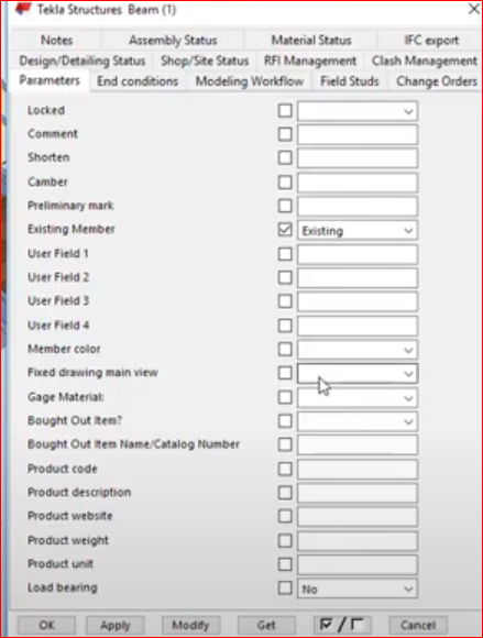
Existing Member Did you set the existing member user attribute to Existing so that no mat list, Drawing will be created