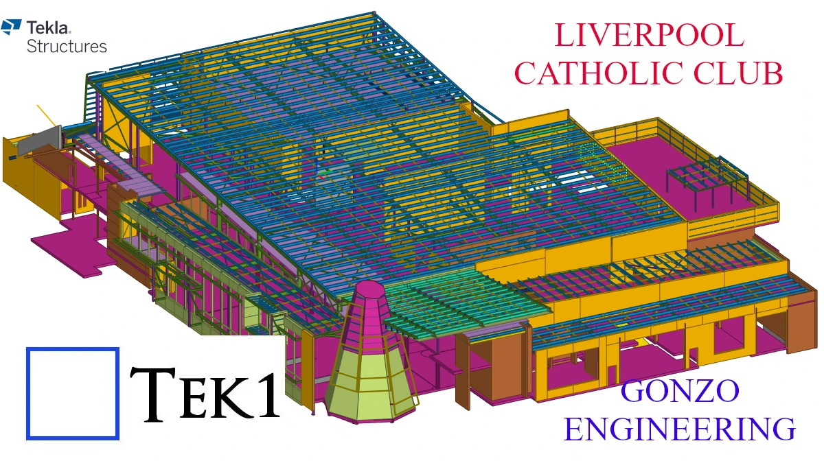
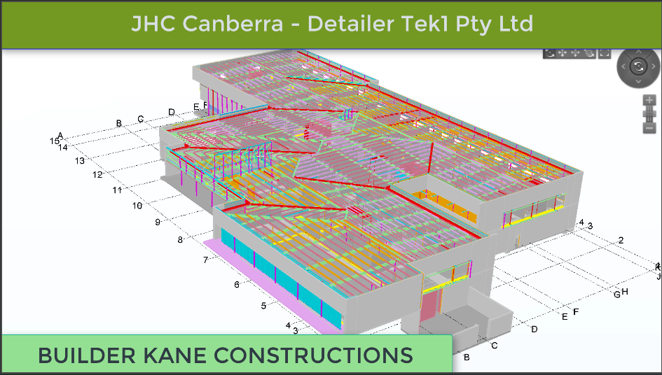
Tek1 has completed this rather complicated project with support from a brilliant detailing team. The project was complex demanded a very high level of detailing knowledge. We have put our best guys on this job. They have done wonderfully well in completing this project without a hitch. The builder in this instance was Kane Constructions. The fabricator Gonzo engineering.
You may visit our Services page for more information for the type of work we doe
There are big risks involved with working with existing Steel
Things to note.
RL /Height Measurements.
You probably will have to give careful consideration as to what was site measured and what references were used.
Most common errors
Heights measured from Floor to underside of beams. But the floor is sloping
Beam Cols side or centerline used as a reference. But Size and Orientation of beam not confirmes. Both Size and Orientation should be confirmed
The measurement from a wall given. But the wall does not run parallel. By the time the measurement comes to the level we need, measurements are out.
References are taken from something which we cannot reproduce accurately on our drawings.
Site measurements do not add up to the overall. (This is common.) You have to ask which references we should be using and use the same references to set out the members.
Measurement errors could create erection problems. Analyze potential problems and counter for that.
Be extremely careful when the site measure is not from the total station. Most of the errors we see are from site measures taken with handheld lasers and measuring tape.
Points we have to take care of.
Understand site measure clearly.
Understand Rls and setout which can affect our steel, for example beam, and col size, orientation, Sloping floor. Non-parallel beams.
ASK FOR PICTURES. PICTURES WILL TELL A LOT. ASK FOR VIDEOS TODAY CREATING VIDEO ON THE MOBILE PHONE IS EXTREMELY EASY SO ASK FOR IT
Pop-Quiz: What’s wrong with the below connection detail?
Consider the details below. It’s time for a pop-quiz: what issues can you see here?
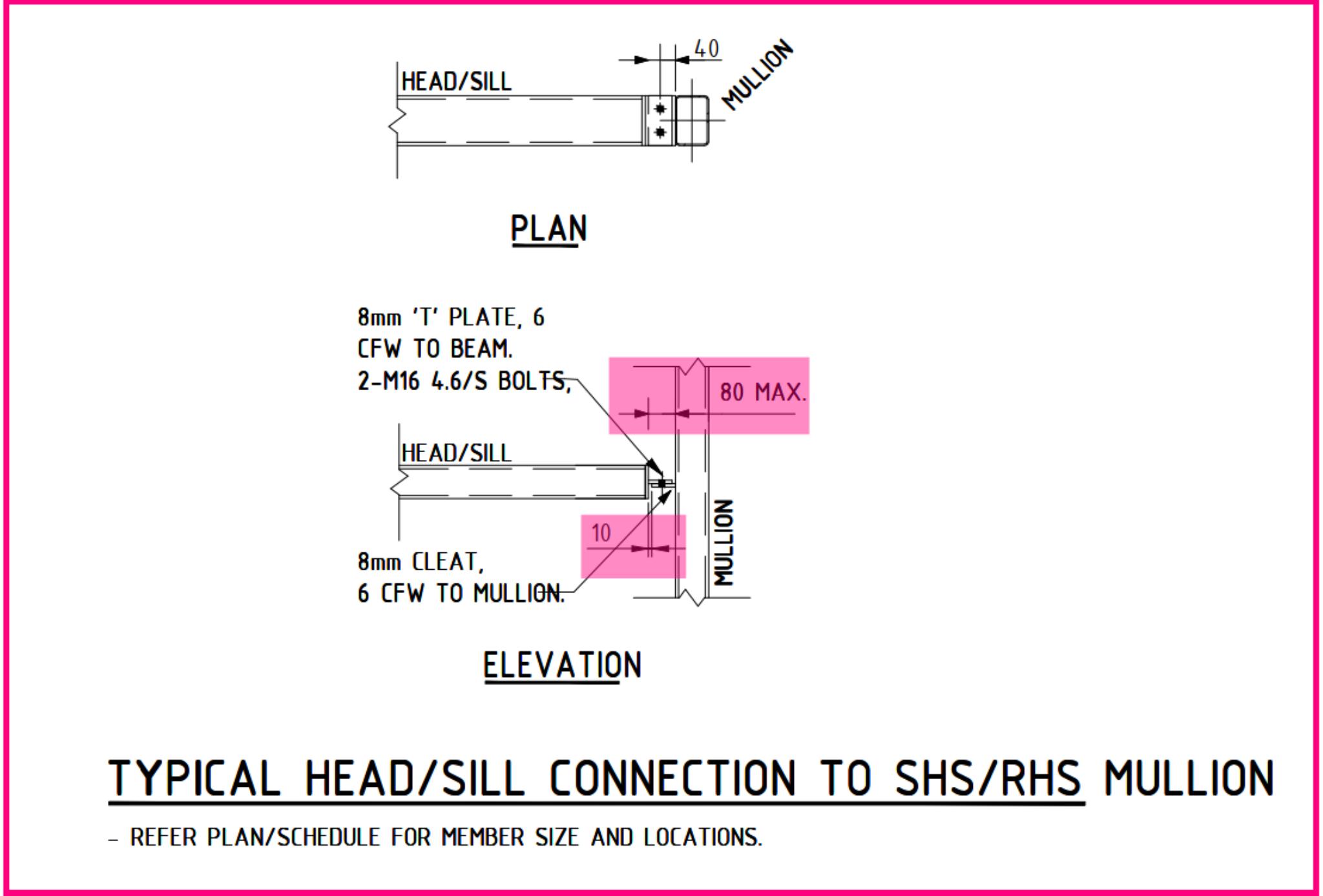
Structural Engineer’s Drawing: Connection details
Answer:
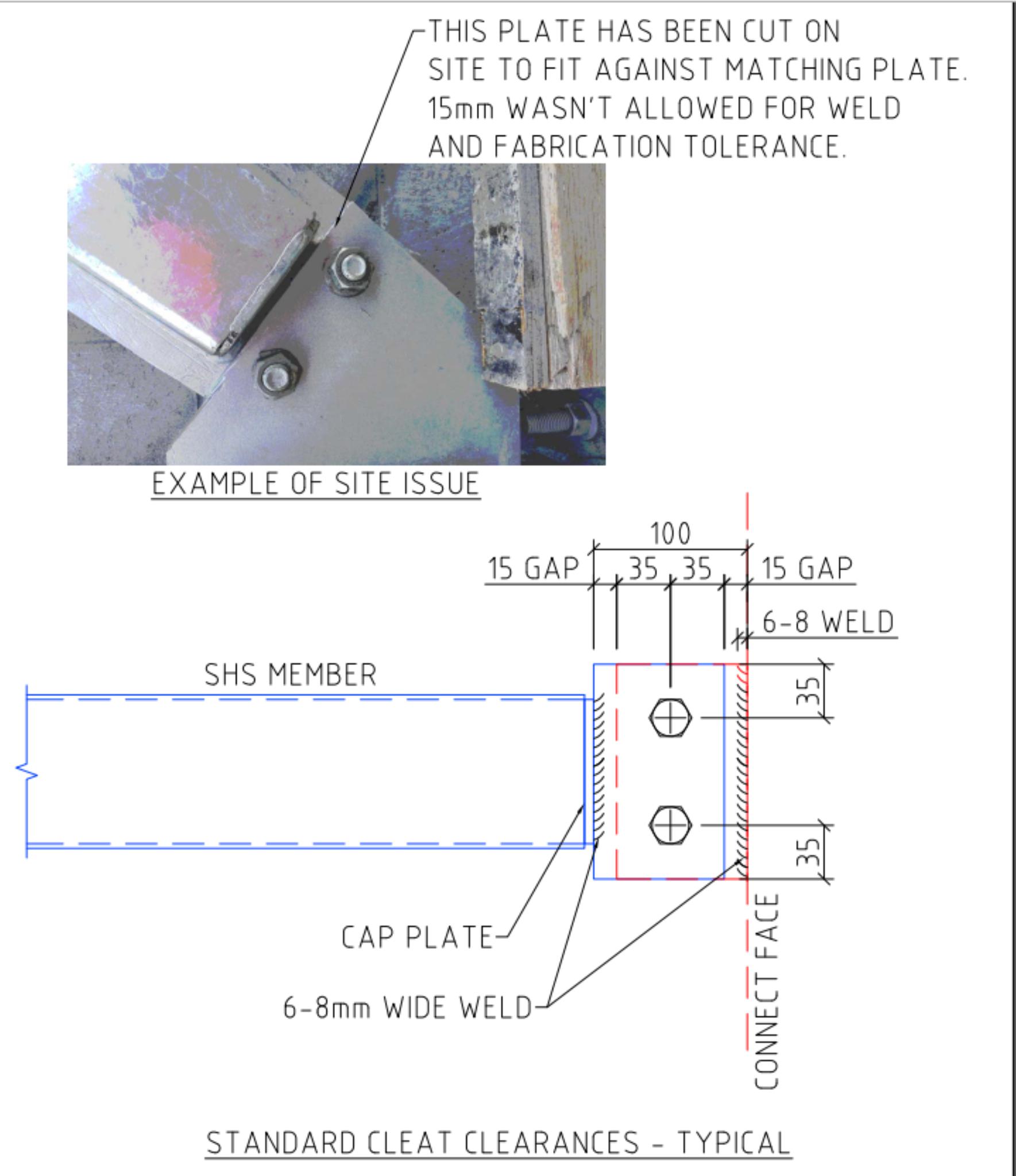
The structural engineer provided the gusset connections with a 10mm erection clearance (see the snap above). But as a steel detailer we must provide a standard min erection clearance for all the connections. (We shouldn’t follow blinding, but we have to think before using their details.).
We must need to provide 15mm min as erection clearance. (because the weld takes up to 8mm). If we give 10mm clearance then the connection plate will hit the weld. It makes erection issue at site. Erection issues are costly and time consuming: resources will need to be occupied on site. Labour is expensive in Australia – and time is expensive anywhere. These sorts of issues need to be absolutely avoided with good detailing practices.
Please refer to the snap below snap: it shows an example of site issues due to insufficient erection clearance. Also we have attached our sketch shows our standard typ connection details.
You need some clearance for the weld. We have also attached a connection detail.
Bonus Marks
What further issues can you see above?
Answer: The plates are of a non-standard size. This means that the fabricator needs to custom make a plate. That involves extra labour, for something that is entirely unnecessary. Plates need to be custom made only when absolutely required.
Kudos to the engineers and architects on this project. Their support had been brilliant. We have never come across another engineer or architect who had been so prompt in resolving issues on this project. We were able to complete this project very quickly mainly because of the super support i
JHC Canberra
n resolving RFIs from the engineers architect and the builder. The builder is Kane Constructions.
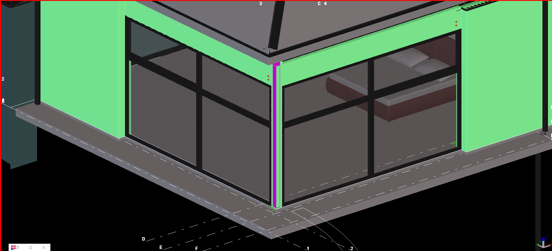
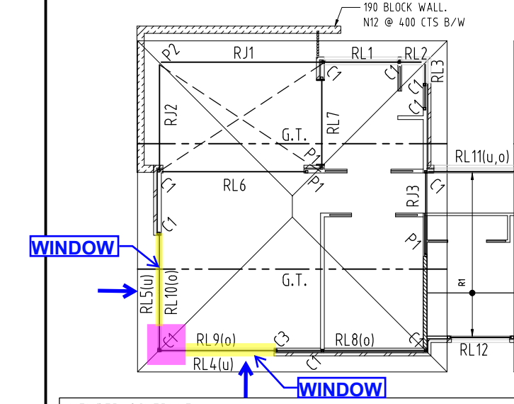
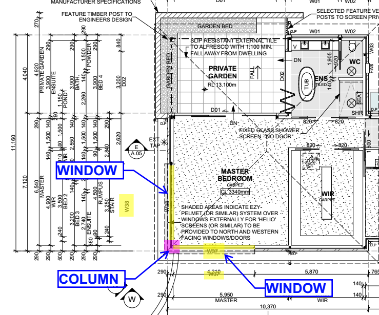
The design drawing requested one column at the wall corner. Also both sides of the corner wall had windows that stand from the finished floor level.
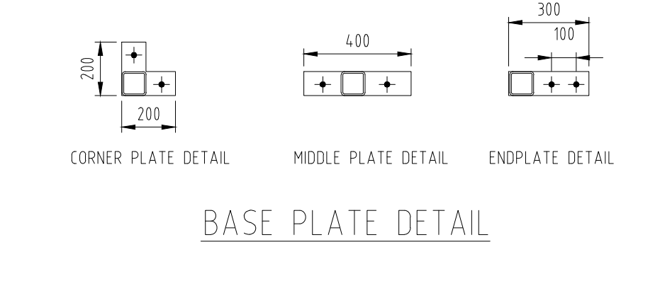
In this instance, we couldn’t follow the structural engineer’s recommended base plate details, because the base plate and anchors will interfere with the window clear open area.
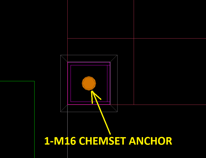
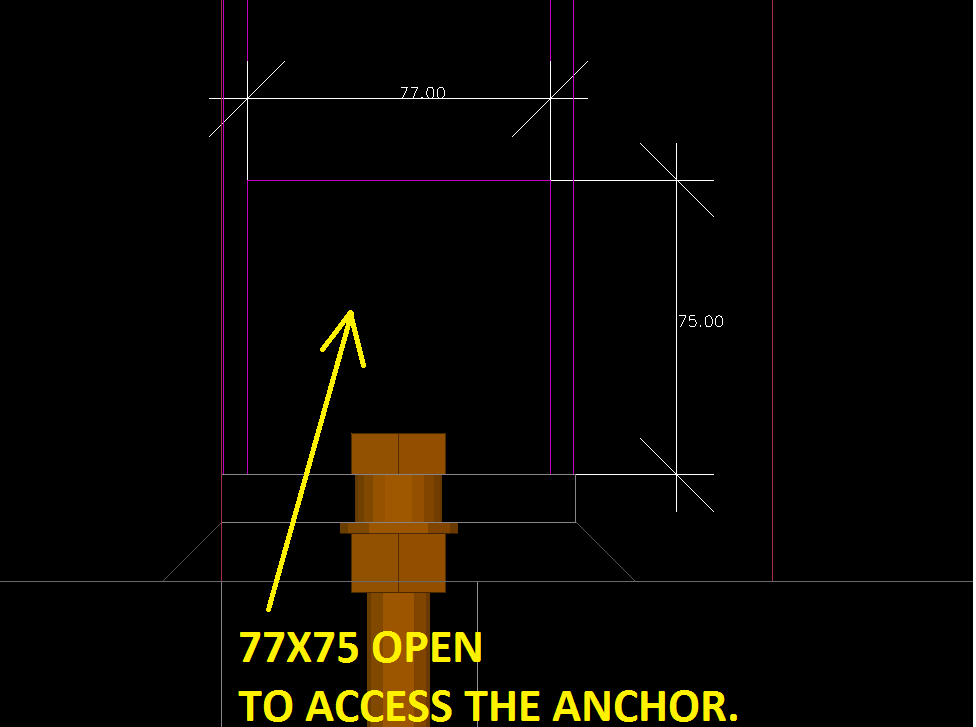
So we suggested the single anchor at the center of the column and make with one access hole in the column web.
The client accepted our suggestions for this case. See the attached snap to understand the issue, and try to spot the problem, and try to solve the problem as if you were facing it for the first time.
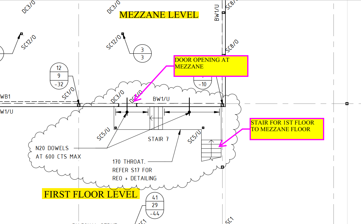
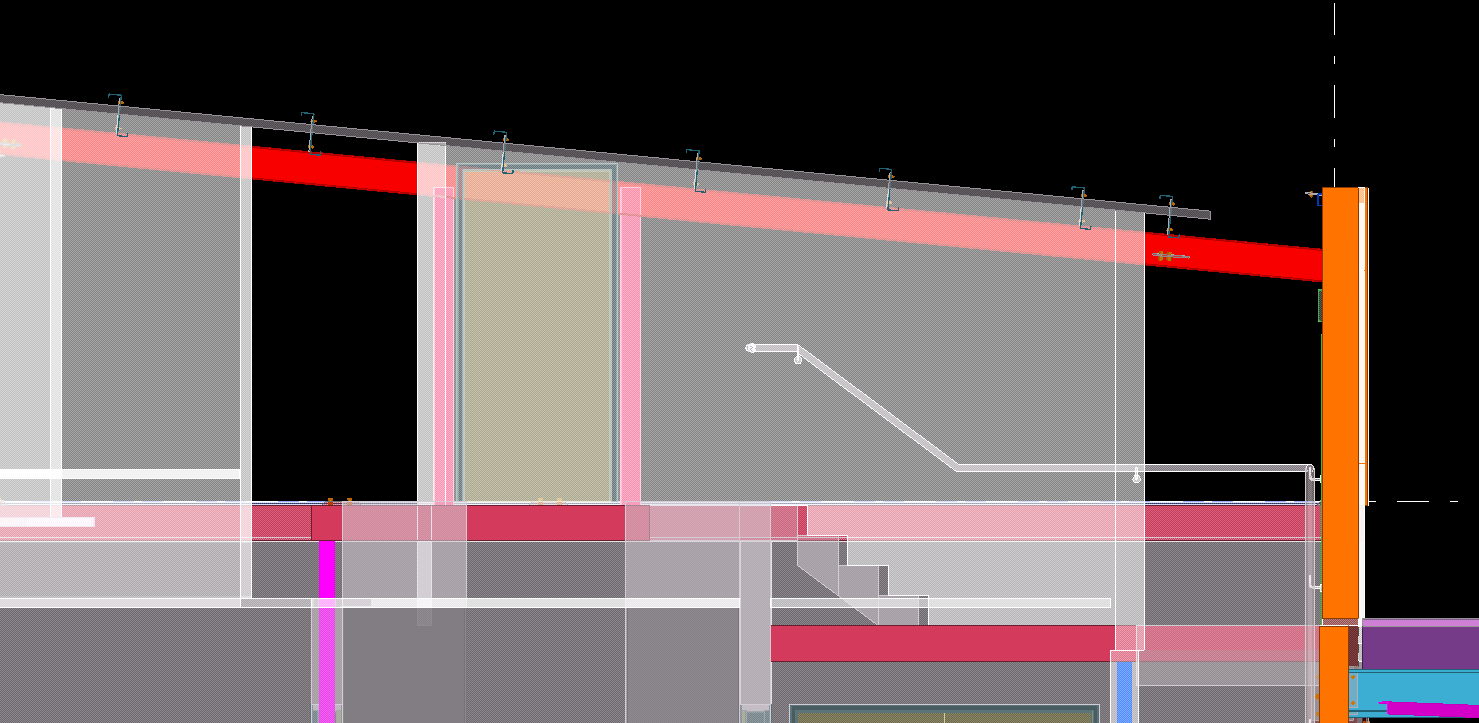
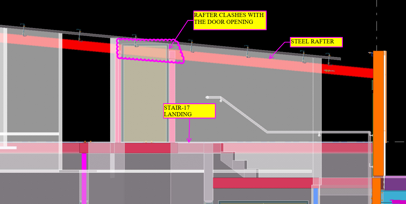
Our detailers identified & noticed that the roof rafter falls at the door opening which runs at 5.5° slope.
The Roof rafter is concealed inside the stud wall, also the Stud wall runs above the Rafter up to the top of parapet RL. The height of parapet wall is the same throughout, hence the top of the wall runs at the same 5.5° slope as the roof.
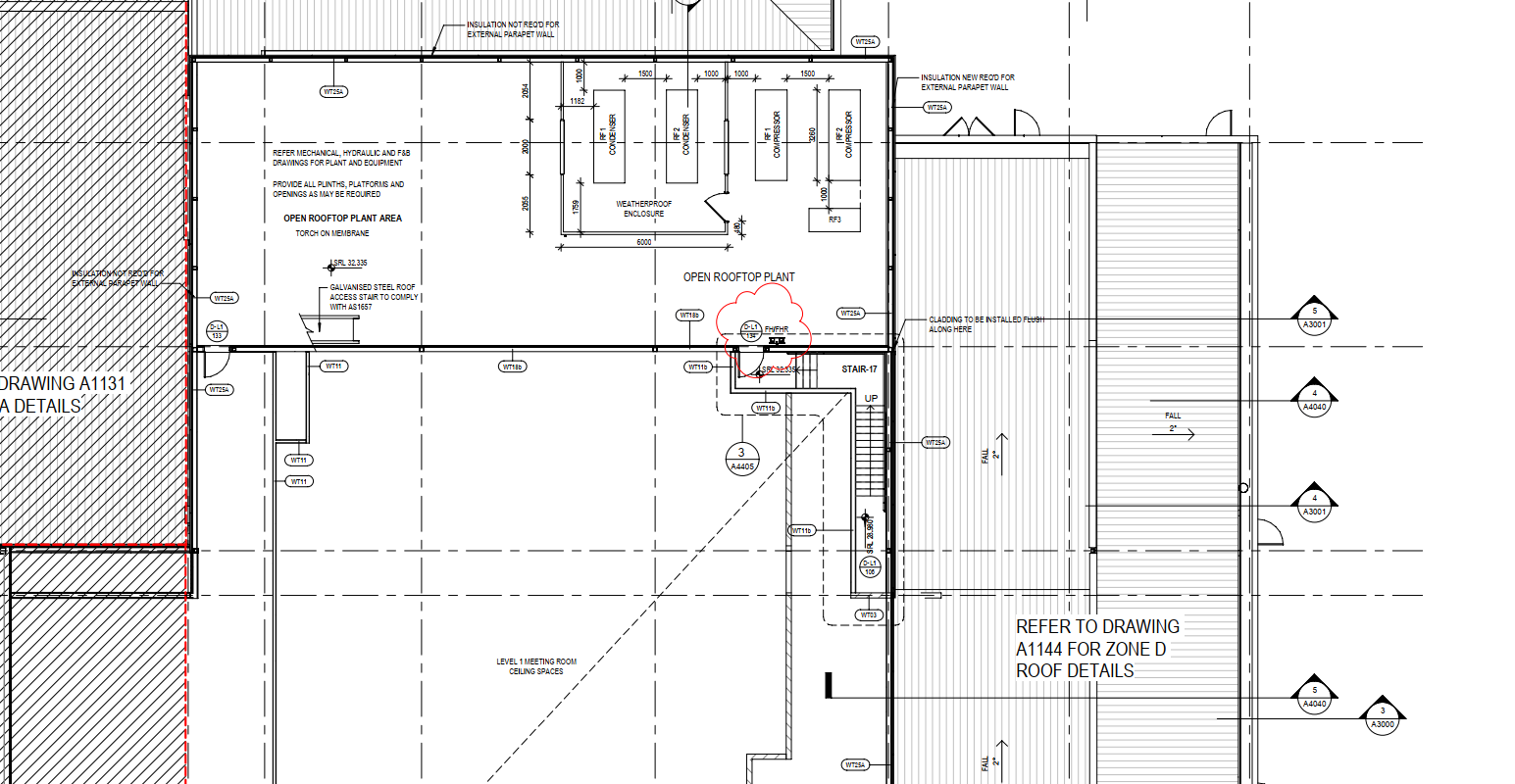
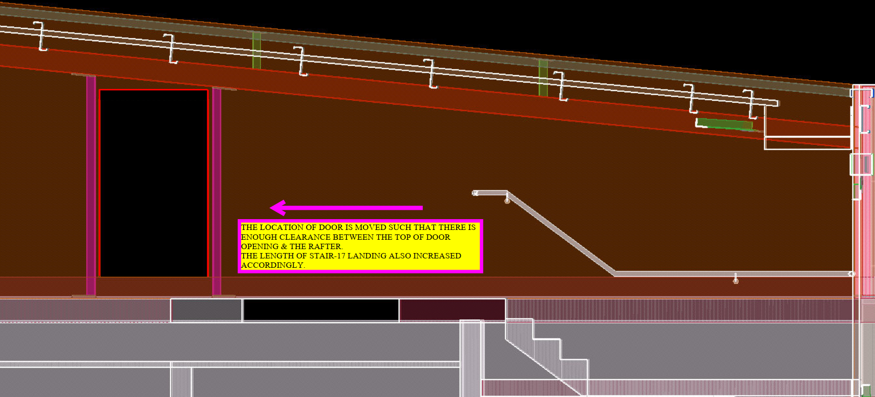
There is an access door near the lower end of the stud wall/Roof. We noticed that the rafter falls inside the door opening and suggested the client to move the door & increase the Stair landing length accordingly.
The suggestion is accepted and the door is moved in such a way that there is enough clearance between the top of door opening and the rafter soffit.
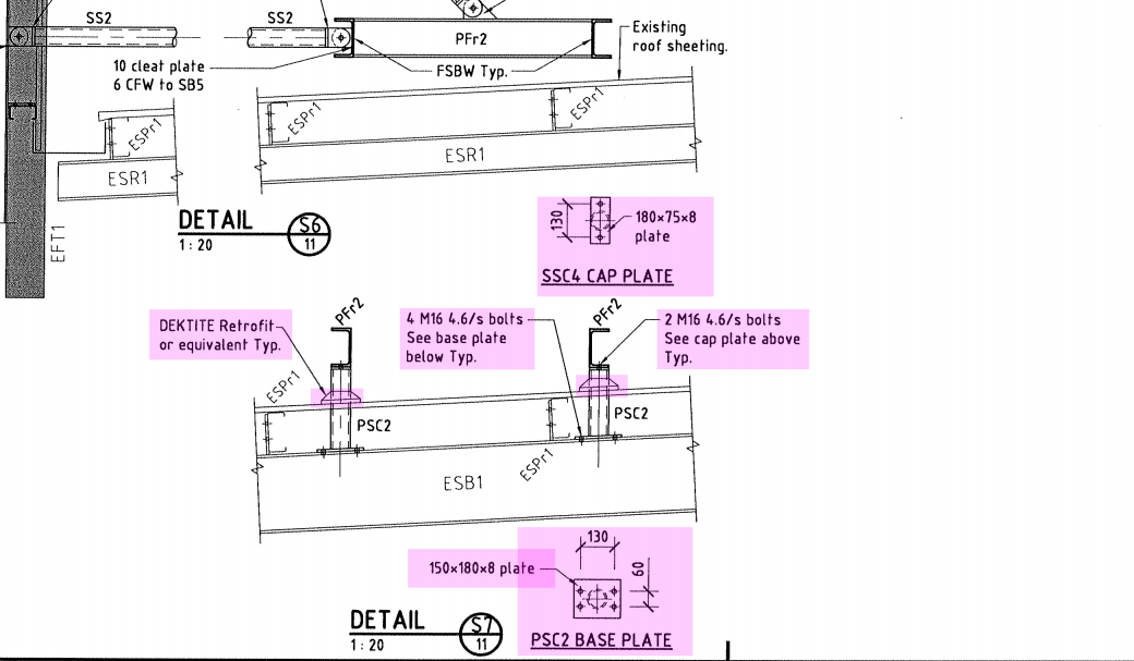
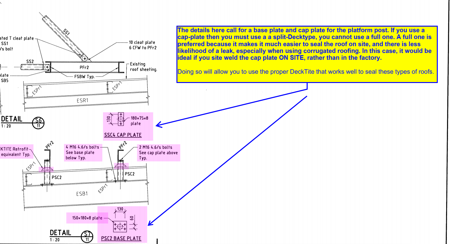
Please study the following drawing. The engineer has called for these details. But as detailers, can you see any issues which may come up? Consider the problem carefully and let us review the issues below. (Given information: the below is a drawing of a corrugated roof. There is a deck to be placed on top of the roof. Hint: waterproofing is the primary concern).
Can you spot any issues with the above drawing?
What is going on here?
The issue lies with water proofing. Corrugated roofing is not flat. It is bent and curved. In this case we have a beam that is penetrating through the roof. In these circumstances, water proofing is critical, and we need some type of Decktite (or equivalent) to be placed on the roof to ensure that water does not seep through. But then, what is the problem here?
To understand this issue, you would do well to watch these two videos first:
The problem lies in the fact that the drawing calls for a cap plate. That is extremely problematic when you are using Decktite. The usual and preferred practice is to pull some Decktite over a pole and slide it down – much like pulling a T-shirt over your head. You can think of the DeckTite as the T-shirt, and your head as a pole. The hole in the T-shirt fits snugly around your neck. But if you have a cap plate, the situation becomes different. In effect, to continue the analogy, having a cap plate is like expanding your head so that it is impossible large to be able to pull a T-shirt over it. You simply cannot put on a t-shirt if your head is too large! The only way to wear the garment is to use a jacket, which can be split and wrapped around – which in this case means using a split Decktite. The problem with using split Decktite on corrugated roofing is that it doesn’t seal as well, and is cumbersome to install.
In this case, you ought to confirm with the client how they want to handle this issue. If you bolt a cap plate on top of the column, then you are forced to use a split-Decktite. But if you want to weld on site, then you can use Decktite that is not split, and can largely avoid the complications of leaks occurring on the roof.
Shows the issues which may crop up if the drawings is followed. You need to confirm these types of issues with the client.