Author: admin

  • Is it supported? (Detailing Tips: No. 2)

    We continue our “Lessons learned” series. Can you spot the snake in the grass, in the following problem?

    There are a million gotchas when detailing, which can trip up even the most experienced detailer. Here’s an issue that snagged us. Hopefully you can learn from our cock-up.

    Showing building supports.
    Showing building supports.

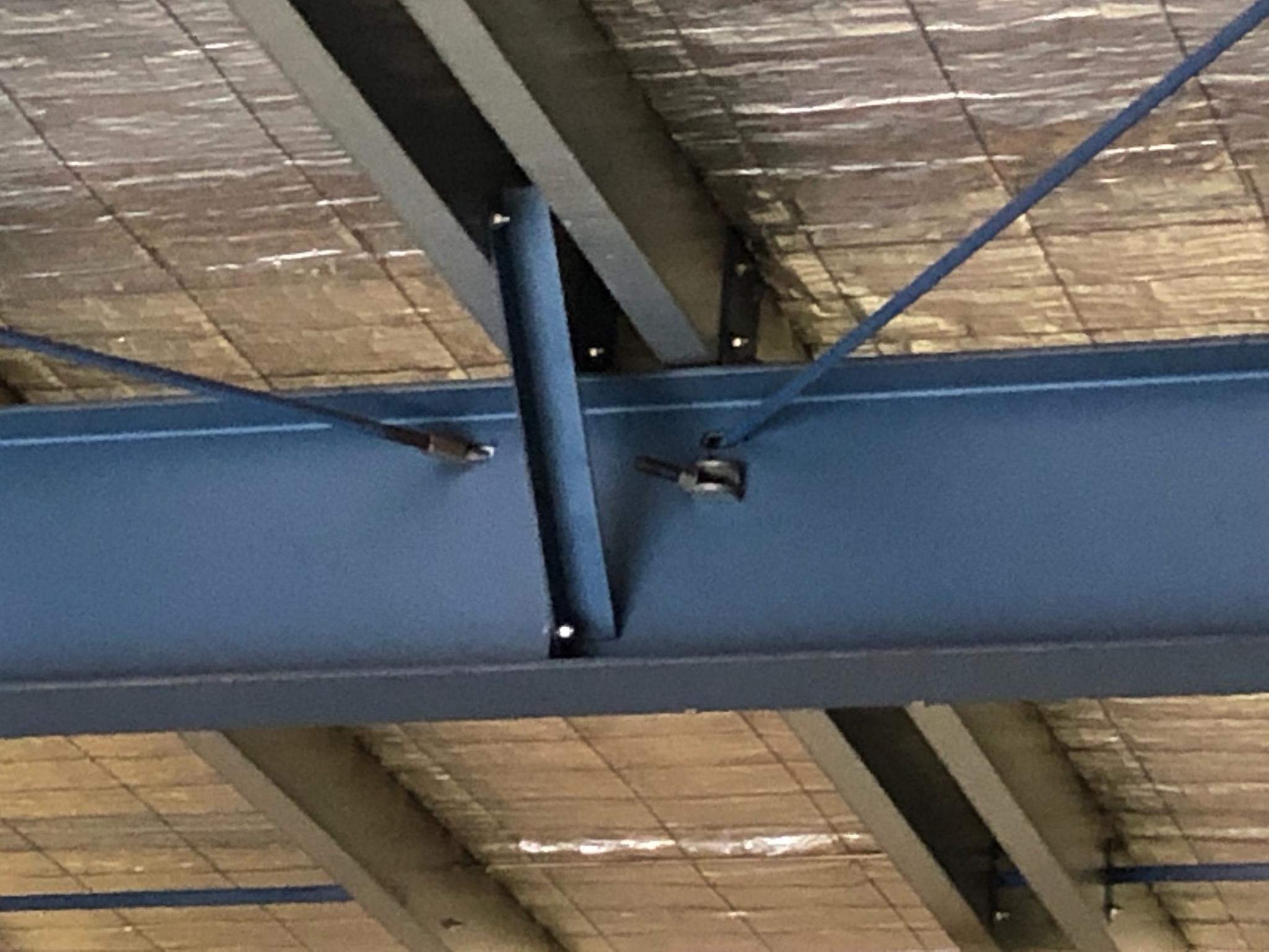
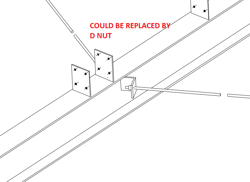
    Generally, roof sheets are provided by the roof sheet erectors. But they want supports for the roof sheets from steel which given by steel detailers. Structural engineers will not give details for roof supports all the time. Sometimes they will miss it, or they will leave it to detailers. If that occurs, detailers must come with their own design (but, must get approval by struct engineers).

    Showing the slope of the roof.
    Showing the slope of the roof.

    There are purlins in this picture to support the roof sheets. Detailers did their job as per structural documents. So that detailer’s work is finished.  Pop quiz: the detailer’s work is finished, right?

    If you think like this, then you are wrong. Have a deep look into that: there are no supports for roof sheets around the perimeter of the roof.

    The supports are missing, around the perimeter.
    The supports are missing, around the perimeter.


    So at this situation detailers must check whether there is support for roof sheets at every ends. If there is any conflict found, you must need to provide steel for roof perimeter supports. Refer below images.

    Here are the steels that are provided by our detailers. This can prevent site issues. Rectification on site is extremely costly, and worse, it’s extremely time consuming. You can avoid nasty delays by some carefully investigating the drawings, and avoiding dangerous pitfalls early on.

    The supports are now drawn. Site issues are avoided.
    The supports are now drawn. Site issues are avoided.


  • Does it Fit? An Example of an Erection feasibility check against particular steel profiles (Detailing Tips: No. 1)

    As a detailer, we should constantly inspect and second guess the drawings and the details given to us by engineers and architects (well, mostly architects, because as a general rule, engineers are competent).

    The Pop-Quiz

    If you wish to engage in a pop-quiz: see the drawing attached here: Spigot Connection. What problems can you see arising if you follow the details put forward. The answers are contained below. Scroll down If you wish to see them.


    Scroll down for the answers.


    Scroll down for the answers.


    Scroll down for the answers.


    Scroll down for the answers.


    Scroll down for the answers.


    ….Ok here are the answers:

    See the link here: Marked Up Pdf Showing Spigot Connection. The structural drawing details the spigot connection required.

    Actually, the Steel post profile size is SHS 89*89*6 and the Steel stub profile size is SHS 75*75*6.

    So we will get an overall 2mm allowance between Steel stub and post.

    In this case we must consider the nature of the steel profile types.

    In the market we are have two different types of profiles, One is Seam SHS and another one is Seamless SHS.

    See how there's a notch here? Ok now we need a bit more clearance. This is because of the process by which this member was created. It starts of like a flat piece of metal, and is basically folded into a square. So the notch will be on the inside, where it is difficult to smooth off.
    See how there’s a notch here? Ok now we need a bit more clearance. This is because of the process by which this member was created. It starts of like a flat piece of metal, and is basically folded into a square. So the notch will be on the inside, where it is difficult to smooth off.
    Notice there is no notch inside?
    Notice there is no notch inside? The clearance can be a little smaller in this case.

    If we use Seamless SHS profile, then we can erect the members, Otherwise if the SHS are of the seam profile type then we can’t erect the member – there is not enough of a clearance.

    Before carrying on the structural details we must discuss with Client/Fabricators and confirm which type of SHS they are going to use.

    If they have Seam SHS only, then we must reduce the stub profile and make more clearance for the easy erection.

    Written By Arokiaraj and his team; Our mistake in this regard was helpfully pointed out by Brett Kennard of Apollo Fabrication. Brilliant.


  • Getting Ordered Intersection Points of a Line along a Particular Direction (Part II)

    This part II of a two part post. Please see part one here.

    We’re moving forward with the next set of requirements. Once we have the intersection points we need to do the following:

    Notice how these lines are staggered (in terms of their offset from the main line) and how the colours are alternating?
    Notice how these lines are staggered (in terms of their offset from the main line) and how the colours are alternating?
    1. Create lines out of them, and then
    2. Offset them from the main line, and staggered them by a specified amount
    3. and color every alternating line a certain color.

    The code to do so is as follows. Hopefully it will be pretty self explanatory:

  • Getting Ordered Intersection Points of a Line along a Particular Direction

    It seems to be a common problem: getting intersection points along a line.

    This is what we want:

    We want the ordered points.
    Notice how the points are nicely ordered, from the start point of the picked line?

    Here’s how I solved it:

  • Ordering Lines using Linq (AutoCAD .net API)

    This is a simple example of how Linq can be used to filter, map and order a set of lines.

    The code is pretty self-explanatory. It is a useful example which can be used to springboard towards further, more sophisticated use-cases according to your own requirements.


  • Precast Tools – Place Sections Command (AutoCAD .net API)

    I’m continuing to write tools to make things more efficient. This is pertinent to precast, and highlights the use of a Jig and also the use of a pre-message filter. You can see a video demo here:


    Place Section Commands from Tek1 on Vimeo.


    And also they key sections of code below:


    Making this better, faster and more accurate!

  • Create new layer filter

    This video explains how to create Layer property filters and layer Group filters for Autocad. nano cad should be same. My nanocad Lic is not yet installed. Using layer filters is a great help to manage your cad files.

    Using layers

    https://youtu.be/9pcJ7OYXUn8

    p

    roperly increases your productivity many folds

  • Lesson 2- Tekla Beam Properties

    In this lesson, I have tried to explain most of the beam properties detailers will use. However I have not dealt with numbering, poly beams and curved beams.

    I will cover that in another video. If you like the lesson please like the video on face book, linked in and you tube.

    I am planning to publish one lesson every week. Let us see how it will go. A lot depends on the feed back I get from these videos

    https://youtu.be/uUatqKlEb2M