These details could be different for each job. Check the details provided by client. If missing ask. The detail Nos will be different. Use what is specific for the job
To give clients certain on what they’re getting: price, quality and timeline.
To sell yourself as capable to do the job.
To fix resources. Everything costs time, money and skill. You will need to allocate resources to get the outcome.
Scope must be white listed in.
If you don’t white list something IN, then new items will CREEP in. This is called “scope creep”. If this happens, and you are being constrained by resources, this means you haven’t accounted for it in the above step(s). Perhaps the entire job needs to be de-scoped.
Without a scope, you are handing over a blank cheque. DON”T DO THIS. Clients want people to make a good margin.
White-listing also forces everyone to be clear on what they want.
Clear Unambiguous Objective:
If you can’t quantify it, then you have a problem.
Scoping will help the client to be satisfied, which is the ultimate objective.
Summary:
Scoping allows you to make resourcing decisions to meet an outcome.
Projections via AutoCAD’s .net API can be confusing. You need to specify a direction, and a plane, upon which you can project a point to. It can be confusing unless it’s clearly spelled out with an example: see below.:
// insert the usual references


Document doc = Application.DocumentManager.MdiActiveDocument;
Database db = doc.Database;

using (Transaction tr = db.TransactionManager.StartTransaction())
{
    BlockTable blockTable = tr.GetObject(db.BlockTableId, OpenMode.ForRead) as BlockTable;
    BlockTableRecord modelSpace = tr.GetObject(blockTable[BlockTableRecord.ModelSpace], OpenMode.ForWrite) as BlockTableRecord;

    // the original originalLine
    using (Line originalLine = new Line(Point3d.Origin, new Point3d(5, 5, 0)))
    {
        modelSpace.AppendEntity(originalLine);
        tr.AddNewlyCreatedDBObject(originalLine, true);

        // but we want to project it ONTO a plane.
        Plane plane = new Plane(Point3d.Origin,  new Vector3d(0,1,0));

        // project the originalLine onto a plane.
        Matrix3d projection = Matrix3d.Projection(plane, - Vector3d.YAxis);

        Line projectedLine = new Line(originalLine.StartPoint.TransformBy(projection), originalLine.EndPoint.Project(plane, -1 * Vector3d.YAxis));
        plane.Dispose();


        modelSpace.AppendEntity(projectedLine);
        tr.AddNewlyCreatedDBObject(projectedLine, true);
    }

    tr.Commit();
}
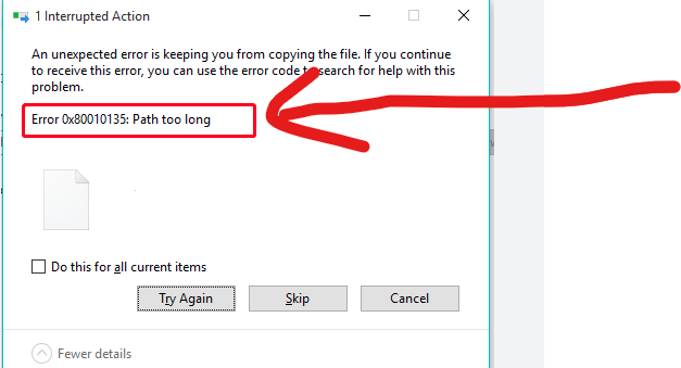
In the construction business – you will often find yourself zipping / unzipping large sets of documents, and copying them from A to B etc. Often when dealing with deeply nested folder structures, you will get an error – regarding long path names. Like this:
This is especially annoying if you are copying large sets of documents.
Ordinarily I would suggest that clients avoid deeply nested folder structures – but then I thought: who am I to presume to how anyone should structure their affairs?
Why not allow for long file paths in the first place? This is how you can do it?
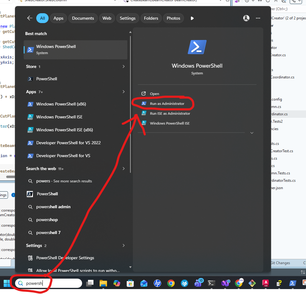
Open PowerShell in Adminstrator mode:
In the Administrator terminal, run the following command by cutting and pasting the following:
We are now placing smart QR codes on drawings. Why? What benefit is accrued by doing so?
You can see a 3d view of an assembly.
You can conduct spot measurements of the assembly.
You can check whether your drawing is the latest revision.
You can add markups directly to a document number – and see it’s revisions over time
Instructions on how to make it work
Set up a project on prolox.io
Get the project’s public access token.
Log into the Prolox’s Tekla’s client application. Use your prolox login email and password and the project’s public access token.
Using Tekla 2023 and with the relevant model open (please open only 1 model) – run the client code.
All the values will be updated.
Rules – To prevent obsolete data from being used or shown
If you update the model, you must re-upload the IFC file in prolox.
If you update the revision number, you must re-do the prolox Tekla client program. This will update the revision numbers in prolox.
If you delete a drawing you must update the revision number for the deleted drawing and re-run the TeklaQRCode program. (so that all revision numbers are updated on the cloud, and so that if anyone scans an old drawing, they will be immediately notified.)
Updating the Drawings:
When you update the drawing PLEASE USE THE SAME REPOSITORY. This is so that we can have old revisions.
Setting up the template
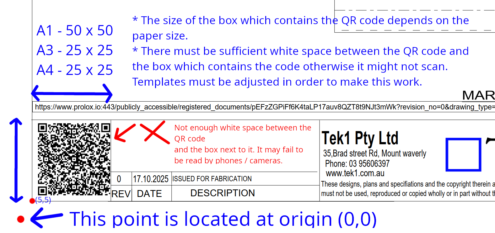
You must set up the drawing template to that the QR Code program works and puts the QR code in the right location. If you don’t set it up properly it will fail.
Assume each page has an origin point of (0,0) at the bottom left hand side of the page.
The drawing template’s borders start at (5,5).
There must be a good amount of white space between the QR code and borders, otherwise the QR code may fail to be read. Which means the entire thing fails.