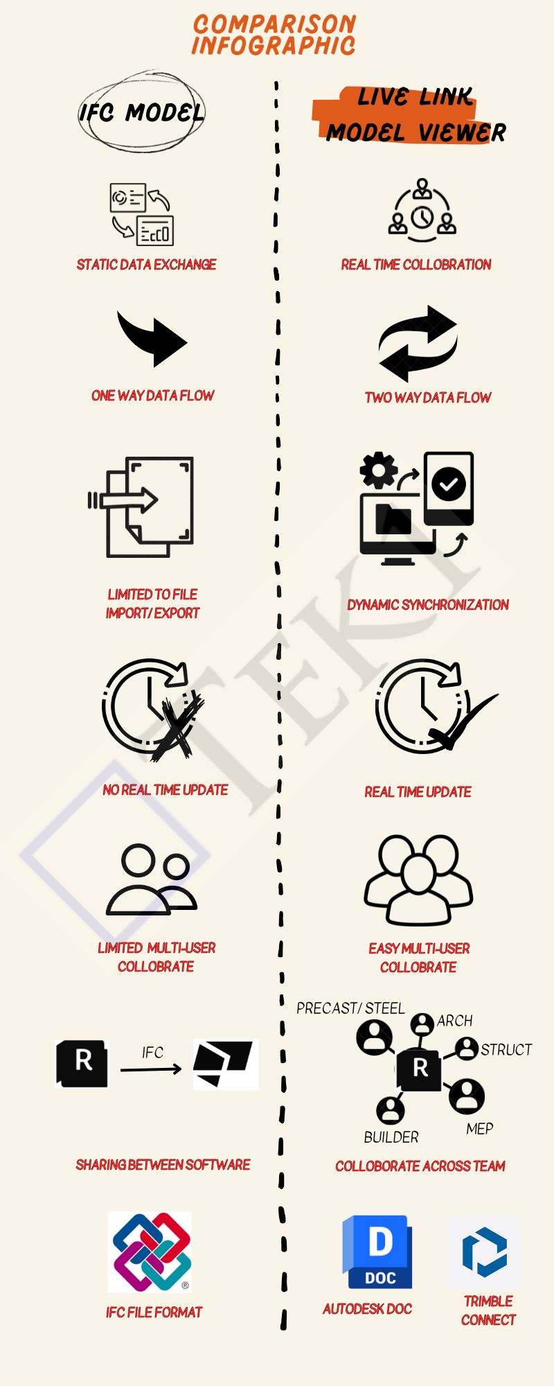
If You Have to share a Model With Consultants, but they do not have the Same Software.
To guarantee that your content File format is compatible with several tools.
You are creating a static data exchange project, not real-time collaboration.
Use Live Link Model Viewer When:
You want real-time collaboration between two to n users or teams.
Save time and effort lost to exporting/importing files from one software tool to another
You are working on a multi-disciplinary project that needs coordination, such as Arch, Struct, and Service Engineer design.
Conclusion
If you’re looking for a simple, static way to share data between software tools, IFC is the way to go.
However, if you need real-time collaboration, dynamic data sharing, and seamless teamwork across disciplines, a Live Link Model Viewer is a better choice.
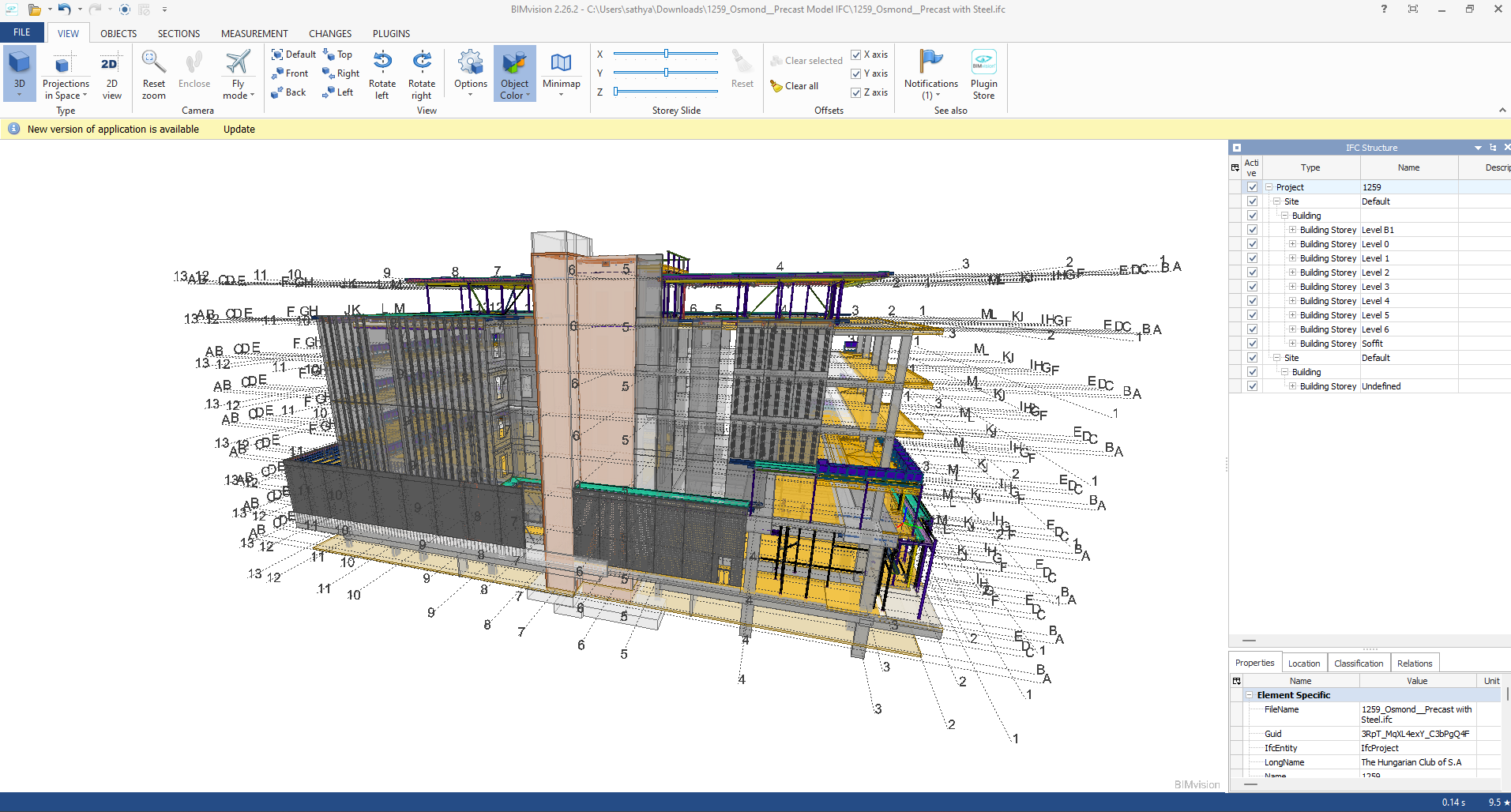
Industry Foundation Classes (IFC) is an open file format developed by Building Smart Alliance. It is an international data exchange standard for exchanging building information across different software platforms. An IFC Model is just a model of a building or a construction project with all geometric, structural, and semantic information.
Key Features of IFC Models:
Open Standard: IFC is vendor-independent, i.e., any software that supports it can be accessed, without regard for the vendor.
Static Data Exchange: It is mostly utilized for data exchange between software tools, data import, and export. For instance, an architect can create a model using Revit and export it as an IFC file, which can then be imported into structural engineering software like Tekla or SAP2000.
Limitation of Real-Time Coordination: IFC files are representations of the model at a specific moment. Changes in one application are not duplicated in another except where the file is re-exported and re-imported.
Use Cases:
Exchange of models between stakeholders with various software.
Ensuring interoperability in interdisciplinary projects (e.g., construction, engineering, and architecture).
Advantages of IFC Models:
Encourages collaboration and interoperability in BIM workflows.
Reduces errors by making sure all stakeholders are working from the same information.
Allows clash detection and coordination between different disciplines.
B. Live Link Model Viewer
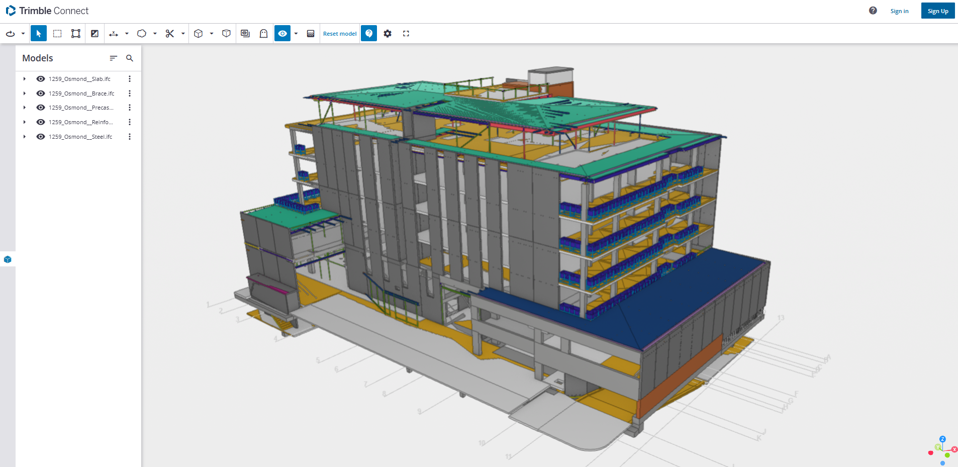
A Live Link Model Viewer is software that enables real-time sharing and visualization of BIM models on various software platforms. Unlike IFC models, which are pre-exported static files, a Live Link Model Viewer enables multiple users to work on the same model at the same time using different software programs. Common examples of Live Link Model Viewers are:
Revit Live: A cloud-based collaboration platform by Autodesk.
Trimble Connect: A BIM data management and sharing tool.
Key Features of Live Link Model Viewers:
Real-Time Collaboration: One software application’s changes are reflected immediately in the model viewer and other linked applications.
Dynamic Data Sharing: Unlike static IFC files, Live Link Model Viewers offer dynamic, real-time linking between software applications.
Multi-User Collaboration: Multiple stakeholders can view and edit one model at the same time even though they are in different software.
Use Cases:
Real-time collaboration among architects, engineers, and contractors.
Collaborative design review and clash detection.
Smooth communication between teams working on different software platforms.
Advantages of Live Link Model Viewer Benefits:
Make collaboration more effective and faster.
Eliminate the need for repeated file imports and exports.
Enhance accuracy by getting the entire team to work on the current version of the model.
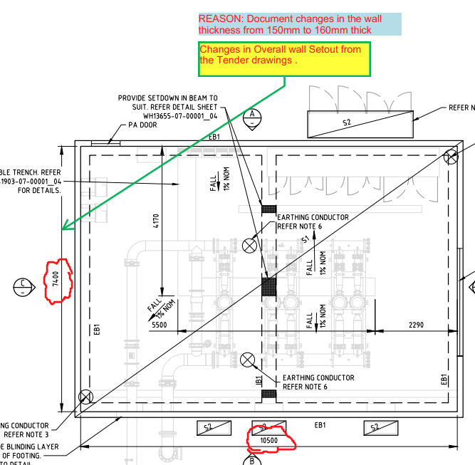
It is essential to cross-check the revised consultant drawings we receive against the original drawings from the Quotation stage before commencing the project because this may affect prices.
For example, the panel break up, or the panel specs might have changed. If they have changed, this might have a material impact on price such as concrete and reinforcement cost.
What should we do when they make changes?
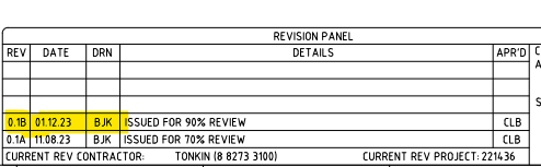
Check the consultant drawing revisions and their date (between the quotation and the current stage).
For example:
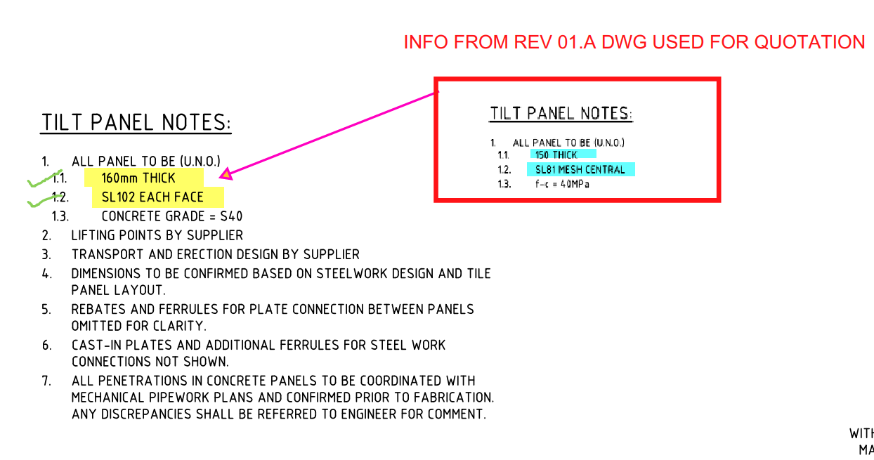
2. Highlight the changes that occurred and mark them down in the latest structural PDF.
For Example:
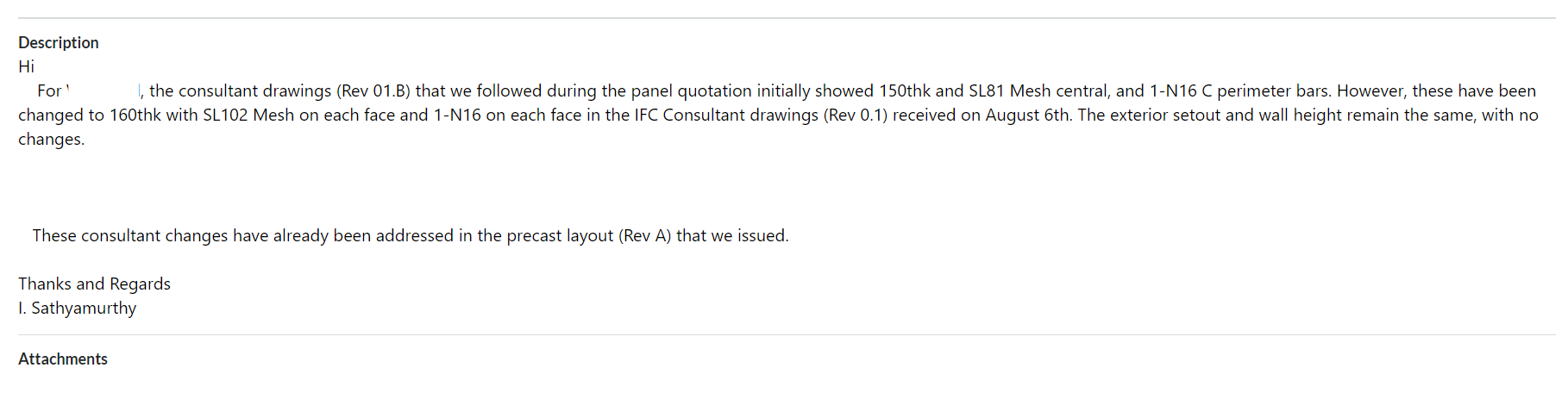
3. Prepare a summary document report outlining the modifications.
For Example:
4. Inform the precast manufacturer and builder about these changes by sending the relevant information via email.
For Example:
Why do we need to check the consultant drawings?
This verification process will enable the precast manufacturer and builder to re-evaluate the timeline based on the information that was previously quoted. This allows potential Cost issues that could cause confusion or delays in the project timeline to be identified and resolved early on such as
Cost estimation of individual precast panels, including their respective panel areas and concrete volumes, for manufacture.
Cost estimation of approximate reinforcement and mesh weight requirements.
List of cast-in items and loose items required, approximate quantities.
What are the key factors that need to be verified in the consultant drawings from a precast perspective?
Panel Thickness and Types: Verify the panel thickness and types used, as specified in the Structural Drawings.
2. Panel Count: Confirm the panel count based on the panel split, as detailed in the Structural Drawings.
3. Panel Transportability and Tonnage: Conduct a transportability check and verify the tonnage of the panels from our end.
4. Panel Reinforcement:
Perimeter bar diameter
Mesh type used and its placement
Additional reinforcement provided in the panel typical detail
Reinforcement on central or either side ( specify location) (Refer to Structural Drawings for details)
5. Precast Wall Pattern and Special Moulds: Verify the precast wall pattern and special moulds required, as specified in the Architectural Drawings.
6. Panel Finish: Confirm the panel finish, as specified in the Architectural Drawings.
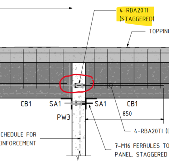
7. Panel Connection Details: Verify the panel connection details, if applicable, as specified in the Structural Drawings
In one of our Projects, Audi Centre Myaree for the Client PARKD Ltd, the typical structural drawing detail represents the precast wall panel which connects to the Delta core slab with RBA20TI inserts.
Two variations of Precast panel thickness have been used in this project: 150thk, and 200thk.
What is the Problem?
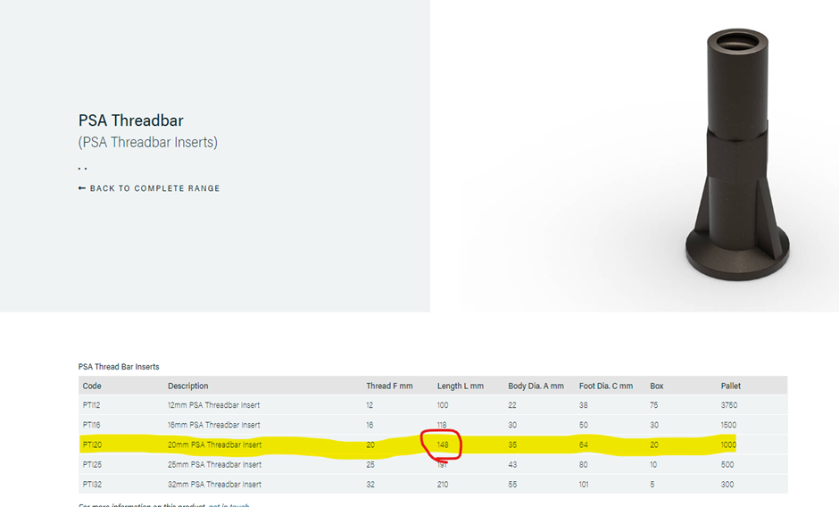
The Insert component RBA20TI or PTI20 are difficult to place on the precast panel face with a wall thickness of 150mm.
Cause for the Problem: Lack of minimum concrete cover is due to component length close to the Panel thickness.
The length of PSA Thread bar Inserts PTI20 is 148mm as per the PSA Schedule.
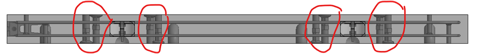
The minimum concrete cover required for this project is 30mm. However, placing the component with a height of 148mm on a Panel with a thickness of 150mm results in no space for concrete cover, as shown below in Image 1
Image 1: Plan View of 150thk Precast Panel with PTI20 Inserts on the panel face.
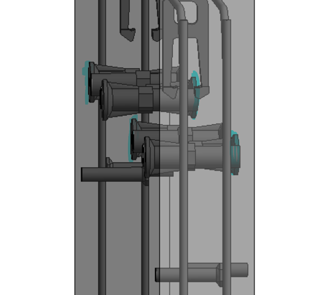
Image 2: 3D view of a 150thk precast panel with PTI20 Insert. The highlighted portion in blue indicates a lack of concrete cover.
3D Model Viewer Link for 150thk Precast Panel with PTI20 Insert:
To retain the 30mm concrete cover in the Precast panel, the PTI20 insert component needs to be replaced with PTI16, which has a length of 118mm. This will result in a 32mm concrete cover, satisfying the minimum cover criteria.
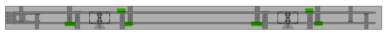
Image 3: Plan View of 150thk Precast Panel with PTI16 Inserts on the panel face.
Image 4: Elevation View of 150 thk panel with PTI16 Insert.
Critical Condition To be Remeber:
Although changing the insert size from PTI120 to PTI16. It is highly required to consider the structural strength of the connection.
The structural strength of PTI16 with starter bars of 16 Ø is lower than that of PTI20 with starter bars of 20 Ø.
To overcome this, it is advisable to increase the count of PTI16 insets by reducing their spacing compared to the spacing provided for the PTI20 insert.
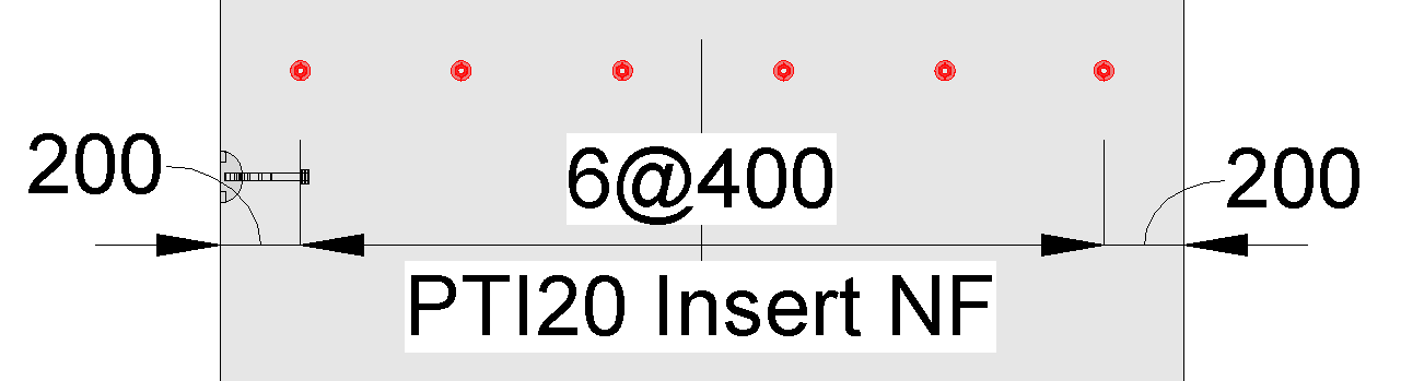
Image 5: PTI20 insert with a spacing of 400 centers
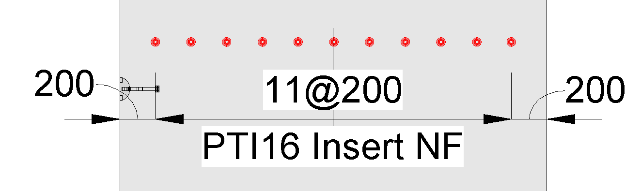
Image 6: PTI16 insert with a spacing of 200 centers (The ferrule count increased to tally the structural strength)
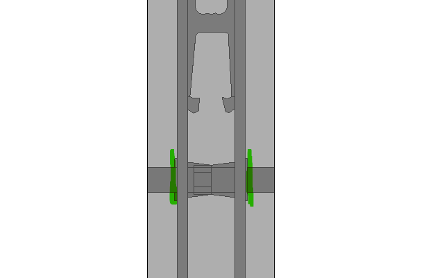
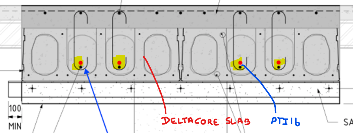
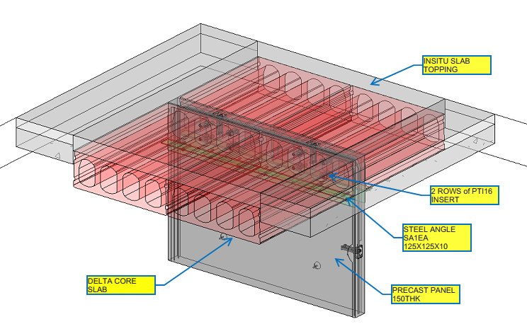
But in our case, since we are using inserts over the Delta Core slab, two rows of PTI16 inserts with a spacing of 150mm are to be placed vertically on the Precast Panel, as shown below
Image 7: Detla Cover connects with the 16Ø Starter bars
Image 8: 3D View of Precast Panel with delta Core
3D Model Viewer Link for Precast Panel with Delta core Connection:
Length of Castin components such as Inserts and Ferrule, needs to be considered about the concrete cover and Panel thickness
If the type of insert or ferrule changes, say from PTI20 to PTI16, to reduce its height, it is mandatory to increase the component count to maintain the structural strength.
Thanks to Robin Hur, Structural Engineer and Project Coordinator from PARKD Ltd, for the support and critical suggestions.
Bim 360 is Construction project management software created by Autodesk. The main intent of using Bim 360 Docs will resolve the following thing
The project status with its workflow with project time frame can be easily tracked by every consultant and organization assigned.
It helps to access the different file formats directly online instead of installing the particular software required
The error can be sorted and make the decision handling by solving the RFI raised to the concerned consultant which can be reviewed and easily sorted by accessing the file / Model directly
Anytime and anywhere access can be easily attained for the projects and their files
The mark-ups review provided by the consultant for the submitted documents can be reviewed and fixed easily
The file can be Access easily frim anytime and anywhere just by login to the Bim 360 in Browser or in mobile
It will make it simple in the documentation handling especially on the revised drawings and tracking the previous submittals history also.
Steps for Creating Project in Bim 360 Docs (Before these steps, log in to the Autodesk account you created in the Bim 360 and select the docs. Click “try now” after that you will see the images shown below
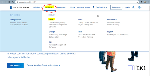
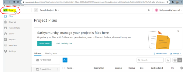
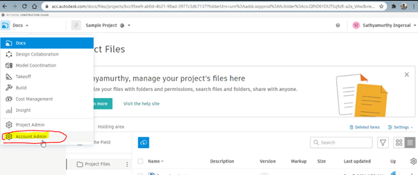
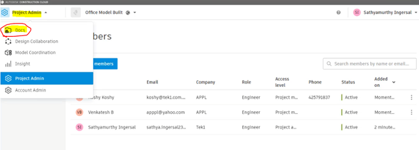
Step 1: Select the “Docs” Dropdown box on the top left corner of the Bim 360 Docs
Step 2: Click on the Account Admin to create a new project
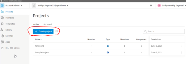
Step 3: Click on to “ Create Project”
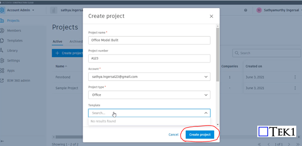
Step 4: Fill the Project Details and Particulars with your Autodesk Email ID and click Create Project
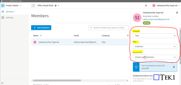
Step 5: Provide your information such as role, access level, and organization on the right-hand side
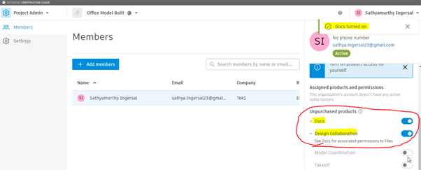
Step 6: Please Turn on the products to be used by moving the scroll down. So that Turned on feature can be accessed as shown in Step 10
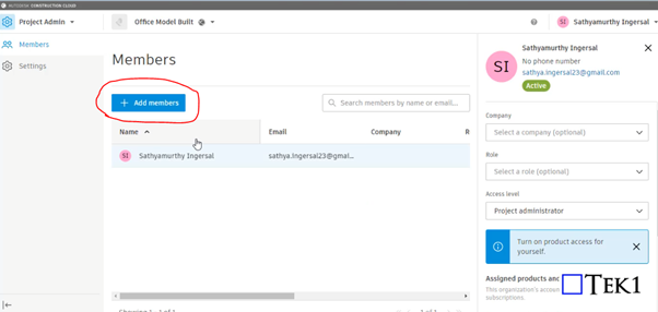
Step 7: Click on to Add member to assign the members who are going to involve and access the files in this project
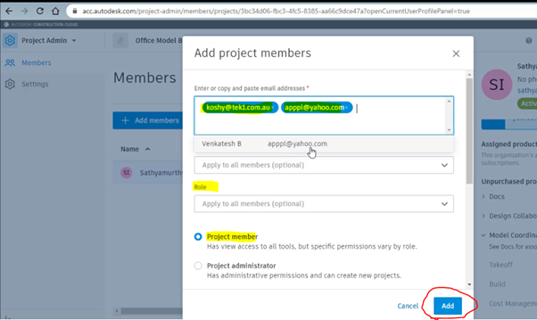
Step 8: Assign the members by adding their Autodesk email with organization name and their role and select as project member and click Add
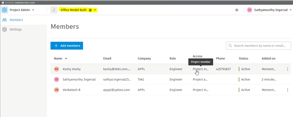
Step 9: After adding the member you can see their active status and details under the project we assigned
Step 10: As we turned on the following highlighted things in step 6. So that now we can access the following by Selecting the Dropdown and click on the docs to upload the file
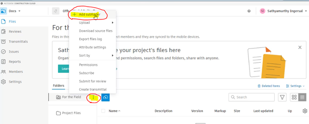
Step 11: To create Subfoler and folder click on to the highlighted below and select Add subfolder
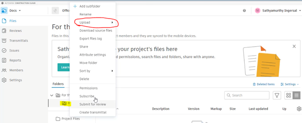
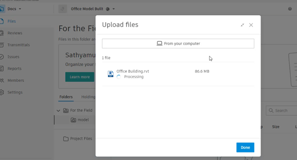
Step 12: After creating and naming the folder right-click to it and click on the upload and file. then drag the file and start upload
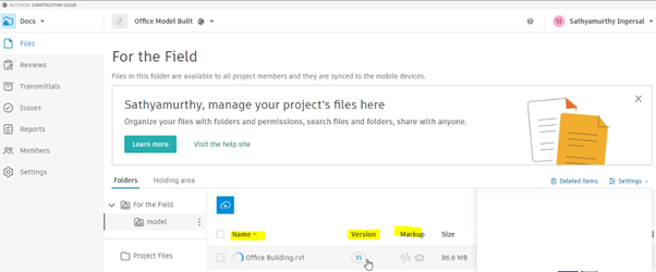
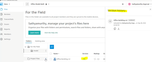
Step 13: The file with its details and version, Mark-ups status will be displayed once the above steps are done
By clicking on to version you can review the history of the file from start to upload till revised. The file model can be review online itself by clicking on Filename
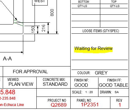
Project Details – Does the Revit file allow us to create Project Details. How and where is the data available to read?
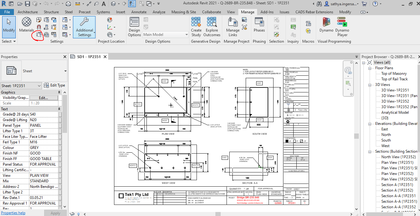
For Project information the details will be added and done in the Manage tab as shown below
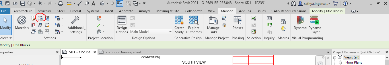
Step 1: Clicking to manage tab and click on the red clouded region as Project Information
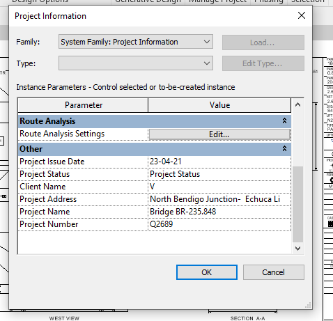
Step 2: Entering the Data about the Project as Shown above
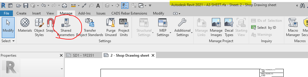
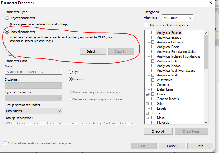
Step 3: Open the sheet family and click on the Shared Parameter Option in the Manage tab
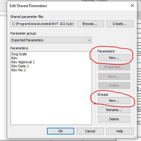
Step 4: Create the new parameter if needed and Create new group where the parameters are to be called for.
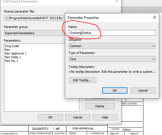
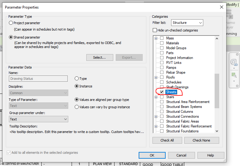
Step 5: Add the new parameter in the Paremter property. Once parameter done it can’t be edited and it has to be removed and create a new one .
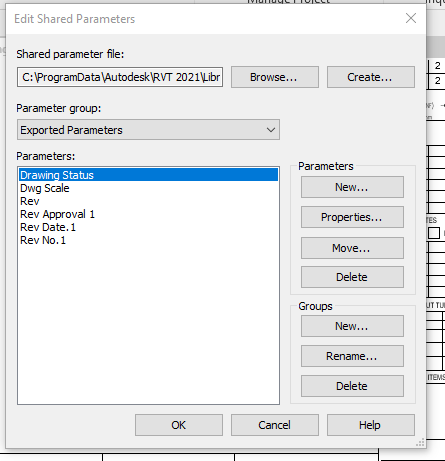
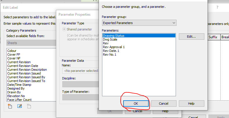
Step 6: Now the “Drawing Status” Parameter are now called under the Parameter group exported parameter.
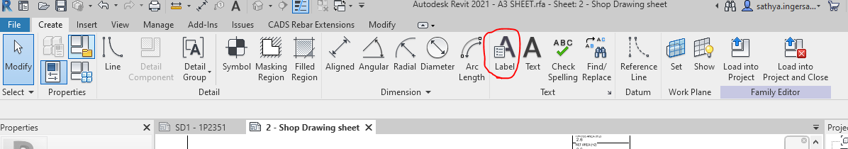
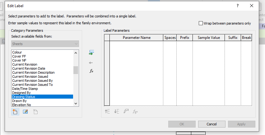
Step 7: Click the Label Parameter to call the label that are already created in parameter
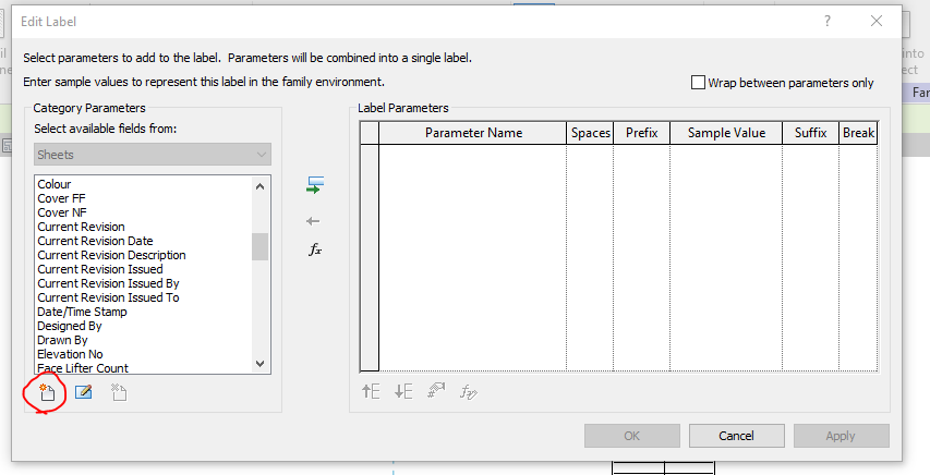
Step 8: The parameter which was created in shared was not displayed so click on the add parameter to call from the group.
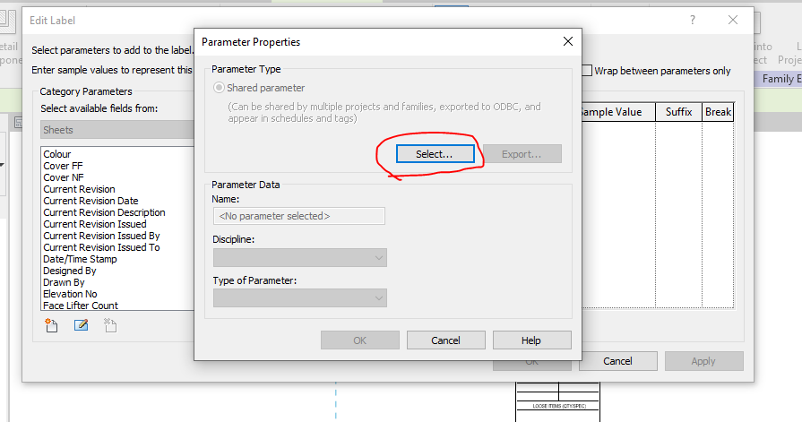
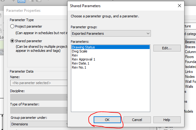
Step 9: Click on the select button to call the shared parameter group defined.
Step 10: Click on the required parameter to call and click on ok
Step 11: The parameter which was not available in the list are now generated and called
Step 12: The parameter which was not available in the list are now generated and called to edit parameter list
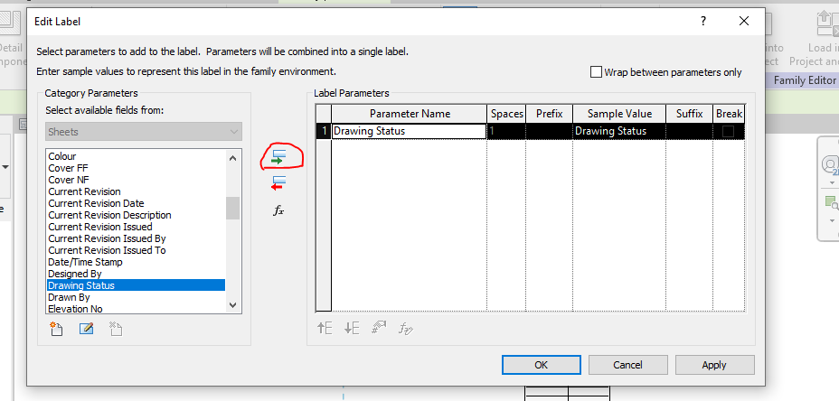
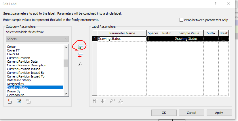
Step 13: Then click the add parameter lab clouded in red and the following parameter will be added in the label and then click ok.
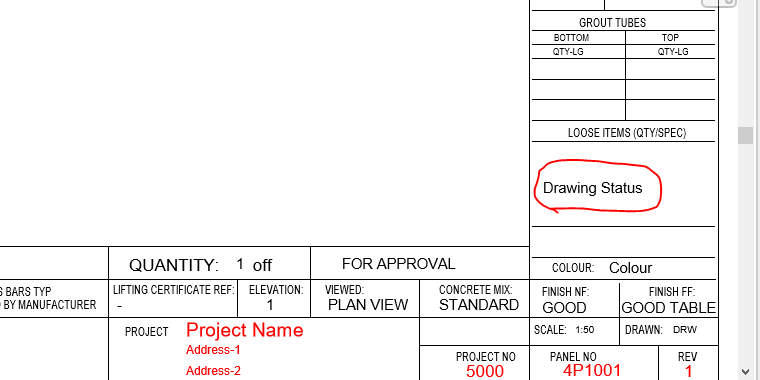
Step 14: The Label “Drawing Status” was now added in the Sheet Family
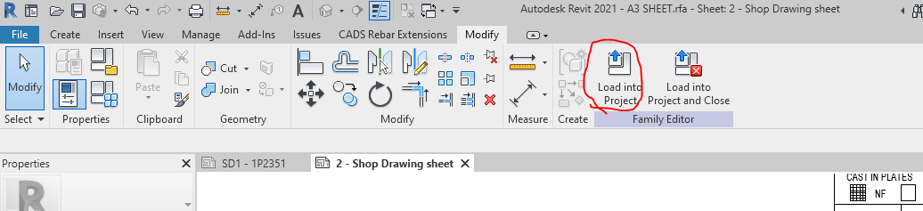
Step 15: Then click on the “Load into Project“ button to load the Shop Drawing Sheet in the Project.
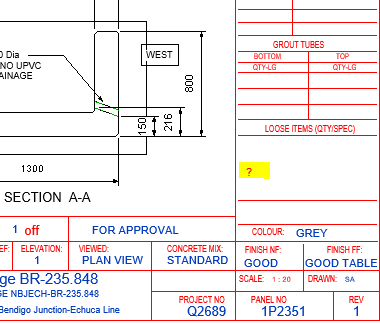
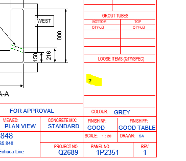
Step 16: The question mark we highlighted are the Parameter “Drawing Status” and it’s not editable at this stage because this shared parameter was not called in the Project Parameter. To sort this please follow the below steps.
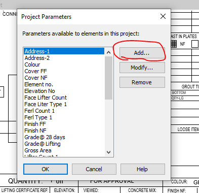
Step 17: Click on the project parameter to call the shared parameter we defined in Sheet family
Step 18: Click on to add button
Step 19: Click on to the shared Parameter and then click select button
Step 20: Click on the Parameter you defined previously and need to be editable and click ok.
Step 21: Once the shared parameter are defined on Project Parameter then click the Check box on the right end shown where the parameter to be display in your revit file and then click ok.
Step 22: Now you can see the question mark colour changes from red to blue which is editable one.
Step 23: The Parameters are added and edited in the Shop Drawing Title Sheet.
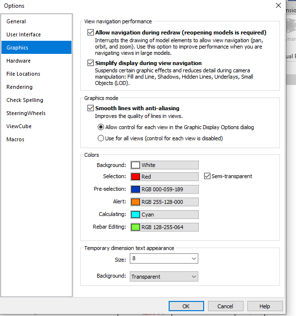
Idea: If you like to make your visuals to find the parameter is in editable or not editable please do the following thing below
Go to file tab and click on the option button below and set the graphics by changing the colours as shown below instead of same colour
Thanks to Koshy, Ben ,Venkat and Parthee for Supporting and guidance .
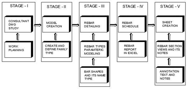
Work Planning and queries preparation based on the information received from structural engineers either as data or from the consultant drawing
STAGE 2:
Model creation for the elements in the Project like Walls , Columns, Beam , Slab ,Footing and stairs based on details and data received. If elements are not standards one means it will be created as families .
STAGE 3:
Rebar detailing and bars arrangements inside the element (Walls, Columns, Beam , Slab ,Footing and stairs) based on the cover distance between the Concrete and rebar. Rebar Parameters and it’s bars shape are reviewed before starting rebar detailing
STAGE 4:
Rebar schedule will be created from the excel sheet generated from the rebar type quantity and its arrangements provided in the element.
STAGE 5:
Sheet creation from the templates based on the sheet size to be used . The excel rebar schedule created are to be dragged and place inside the sheet. The Rebar section views and its detail notes and dimension are created with view pot and scaling, but before proceeding on the above the annotation and text size are to be set and created.