Extraction of individual Bubble deck Slab from Layout to Sheet
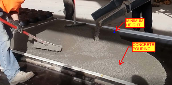
Calculation for Volume and weight for minimum slab pour in Factory
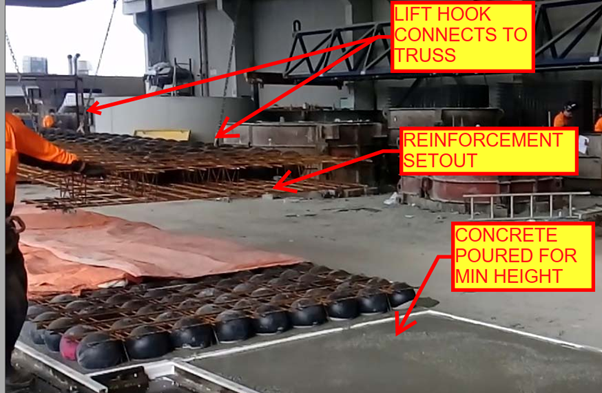
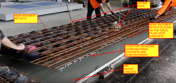
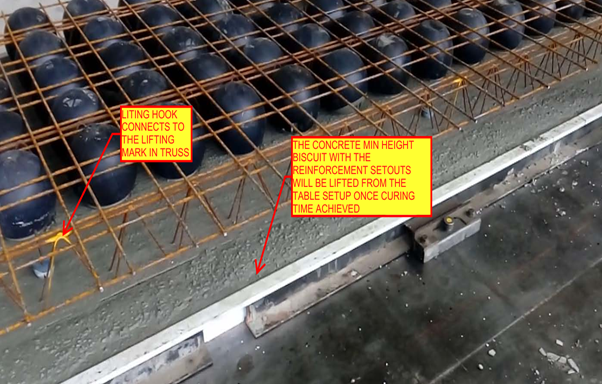
Placement of Lifters on the Min slab pour to lift the Min slab after pouring and curing form the factory
Reinforcement setout panel copied from the Source panel
Reinforcement Arrangements are done based on the Original Slab depth value given to the copied panel
Trimmer bars If the panel has Profile breaks and column Opening
Dimensioning of Panel ball set out for Panel Profile, Balls and cast in components present in the Min Slab Pour
Dimensioning of Reinforcement set out for Slab cover from the start of reo bar. Reinforcement setout Point selection and dimension for Truss arrangement.
Heading Notes for Panel ball set out with finish notes and Reinforcement setout
Notes for Block out and Penetration in Panel Ball setout
Notes for Trimmer Bar , Splice Bar and Loose U Bars in Reinforcement setout
List part for the cast in Components present inside the min concrete Slab
Thanks to Koshy, Ben and Venkat for Supporting and guidance .
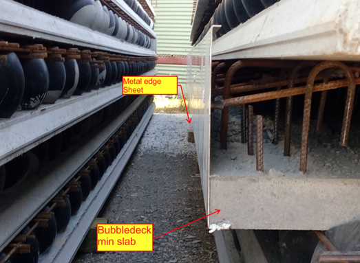
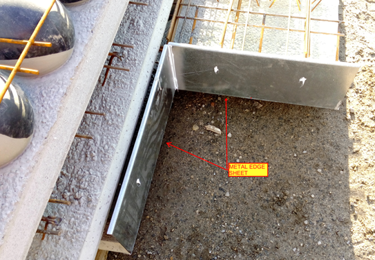
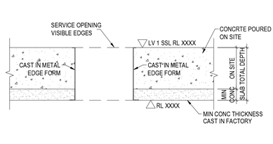
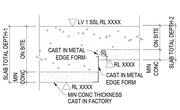
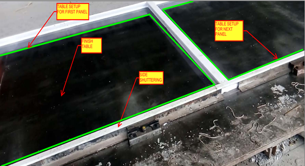
Metal edge is the 2mm to 3mm thick Galvanized Sheet which are mainly placed in the building edges of the Slab to stop the overflow of concrete while pouring on the Bubble deck Slab arrangements.
Metal edges are fixed in the factory and not on site; it will be fixed while pouring the minimum thickness concrete slab biscuit. So the metal edge are comes under the category of castin items in Bubbledeck Slab.
Application of Metal edges:
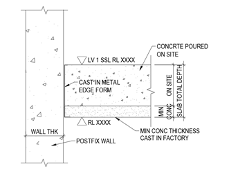
Bubbledeck Slab Edges that connects to Post fixed precast wall (Post fix wall will be erected once after the bubbledeck Slab are installed and Poured).
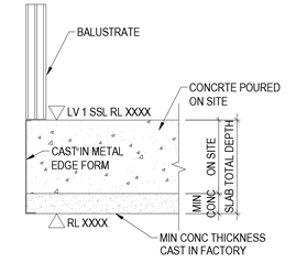
Slab edges which are free from the wall. Especially near to balustrade Areas
Duct and services void in slab which is present inside the Building
Soffiit Step / Slab fall in slab
Advantages :
Fine Finish of slab edge (Visible edges) can be obtained
No side shuttering is needed
Site work can be reduce due to fixing in factory long with min concrete Slab pouring
Disadvantages:
The cost of Metal edge sheet is high compare to timber because of galvanized
The metal edge to be order 10 days prior from casting on minimum concrete because of sheet galvanizing
Handling Problem:
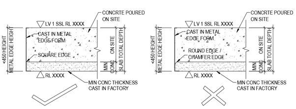
The Metal edge is not safe to use 450mm and above height. This may lead to bend and damage of metal edge sheet during the time of Bubbledeck Biscuit Transportation.
The Metal edge can’t be fixed on the round edge profiles of slab and applicable only for square edge Profile.
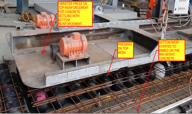
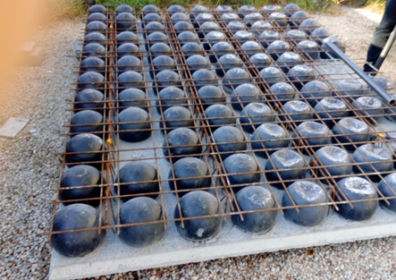
The slab that comprises of plastic void balls in middle which are sandwiched between top and bottom mesh to reduce the dead weight act on the slab
It is a biaxial hollow core slab where the concrete which is not performing any structural function are eliminated lead to reduction in 30% to 50% of its slab weight
Principle:
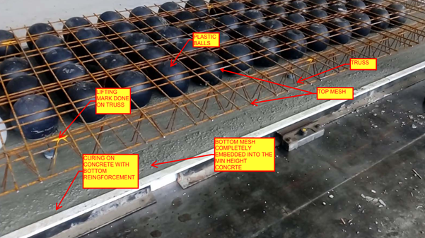
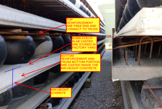
The Hollow plastic balls clamped with the top and bottom reinforcement are placed in the thin concrete of 60mm with max length and width of 10m x 3m to form a precast setup will be done in factory. After that the setup will be installed on site with connecting rods and by pouring concrete
The 35% saving in concrete composition was achieved by the ratio of Plastic ball diameter to the thickness of the slab depth
The reduction in slab weight leads to achieve the Load bearing capacity at a smaller slab thickness result in saving 40 to 50% of material consumption per Floor level.
Materials for Bubble deck slab:
Concrete
Standard with max aggregate size of 20mm
No plasticizers needed for concrete mix
Grade of concrete must be above M30
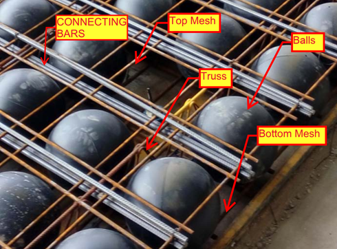
Reinforcement
Grade Fe-600 strength or high
Top mesh and Bottom Mesh reo of N12 bars max
Truss arrangements for vertical support of balls. Truss height depends on slab depth
Plastic Balls
Hollow sphere Plastic balls made of Polyethylene
Diameter of balls are depends on the Slab Depth. Ball sizes are 180mm, 225mm, 270mm, 315mm and 360mm.
Applications of Bubble deck Slab
Superior Architectural Design
Free choice of shape
Large corbels
Large spans and cantilever
No beam and fewer column results in flexibility
Interior design can be easily being altered.
Advantages:
Structural
Reduce the foundation size since 50% of the dead weight is already reduced by the slab.
Increased Strength due to biaxial Loading.
Longer spans are supported since no bean is required.
Column count can be reduced.
Excavation required less work.
Conduits and openings for service ducts can be easily incorporate in factory.
Construction
Less equipment is required due to light in weight.
Less work on Site construction.
Shuttering work and its Dismantling is not required since the 60mm concrete biscuit will act as shutter.
Construction hours and time taken is very less compare to conventional Slab
Engineering
High resistance against explosion due to biaxial flat slab system.
High Resistance to earthquake due to slab acts as elastic vertical structure.
User friendly to Post tensioning if running through slab.
Environment
CO2 emission due to concrete manufacturing quantity are reduced
Less material consumption
Less energy consumption
Less wood as no horizontal scaffolding
Economy
Sustainable for easy installation
Made to measure and saving material
Fast Implementation and construction
Reduction in Transportation Loading cost.
No shuttering and its cost needed
Disadvantage
Deflection will less higher than the Conventional Slab
Load carrying Capacity is lesser than the Conventional slab
Skilled labour required
Shear Load design consideration and its factor near the column area to slab care is required
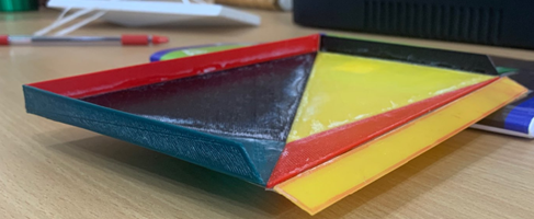
Today we are going to show the miniature Prototype we done on the precast panel and its mould using a 3d printing device.
By preparing miniature we have come across the difficulties and problem that happen during the realistic bound assembly of sheet metal joining for mould and removal of Panel from the Mould setup after the panel casting work completed.
In this case study we will show how the panel removed from the mould set after casting completed by miniature prototype setup
Why Mould needed for this Panel
Normally for rectangular liner profile precast tilt-up panel construction the casting bed with side shutteringwill be used.
Material: Shuttering will be done either in timer or Aluminium Frame
The panel profile faces are sloped or nonlinear and in order to maintain accurate panel profile we need to prepare a separate mould to cast the panel as required.
Material: Mould profile will be done either in Steel Sheet (3mm) or Plate (8mm)
Why Miniature Prototype creation
The main theme of creating a miniature Prototype is by scaling the real time object to check the difficulties and issues that might happen during the process of preparing the Mould and casting the panel with it. By doing this we will be aware where the issue arises and how it can be fixed, so that the cost and time incurred during the real time casting will be resolved.
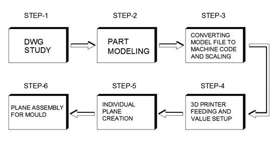
Process of creating Miniature Prototype Creation
Inference
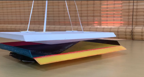
During the process of lifting the panel from the mould, the inner facing splay edges of panel will lead the panel to stop lift from the mould. To overcome this issue one of the inclined splay faces had to be adjustable one (non-permanent fixing) So that after the curing of panel the Mould face will be dismantles to lift the panel from the Mould.
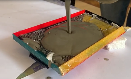
Please see the below Miniature Prototype video of lifting the panel from the Mould after casting done.
The panel has been poured in the Mould Miniature Prototype using Concrete cement with Miniature Reinforcement setup to check further if the panel is all good during the process of casting the panel and the extraction panel from the Mould after the Concrete are cured.
Special thanks to Parthee and Marimuthu for supporting during the Panel Miniature Casting. Thanks to Anandkumar for supporting in Miniature Mould assembly .Thanks to Ben for Supporting in content creation and blogging. Thanks to Koshy , Venkat for providing knowledge towards this idea and help to bring as reality