Subject: Things to do when we have post-tensioning cables passing through precast panels
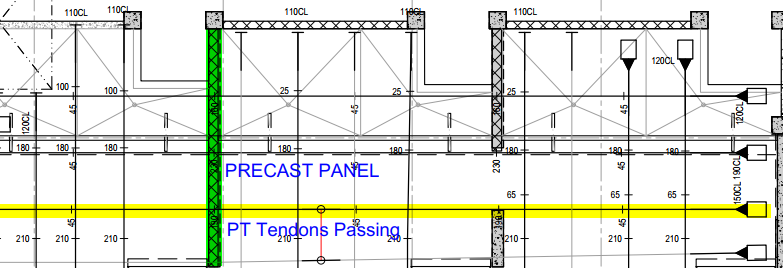
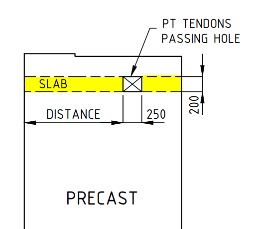
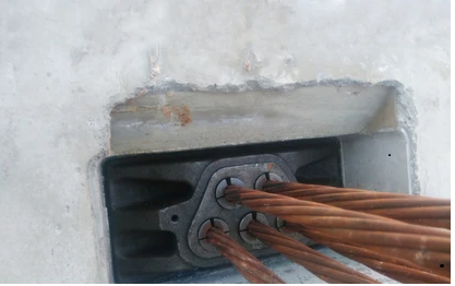
If we have both post-tensioning slabs in the location of precast, we have to provide a block-out hole in the precast to pass the tendons through the precast.
What we care to take when detailing precast panel.
We have to provide an opening in the panel for PT cables to pass through. Do not place any precast hardware closer than 100 mm from the hole/block-out.
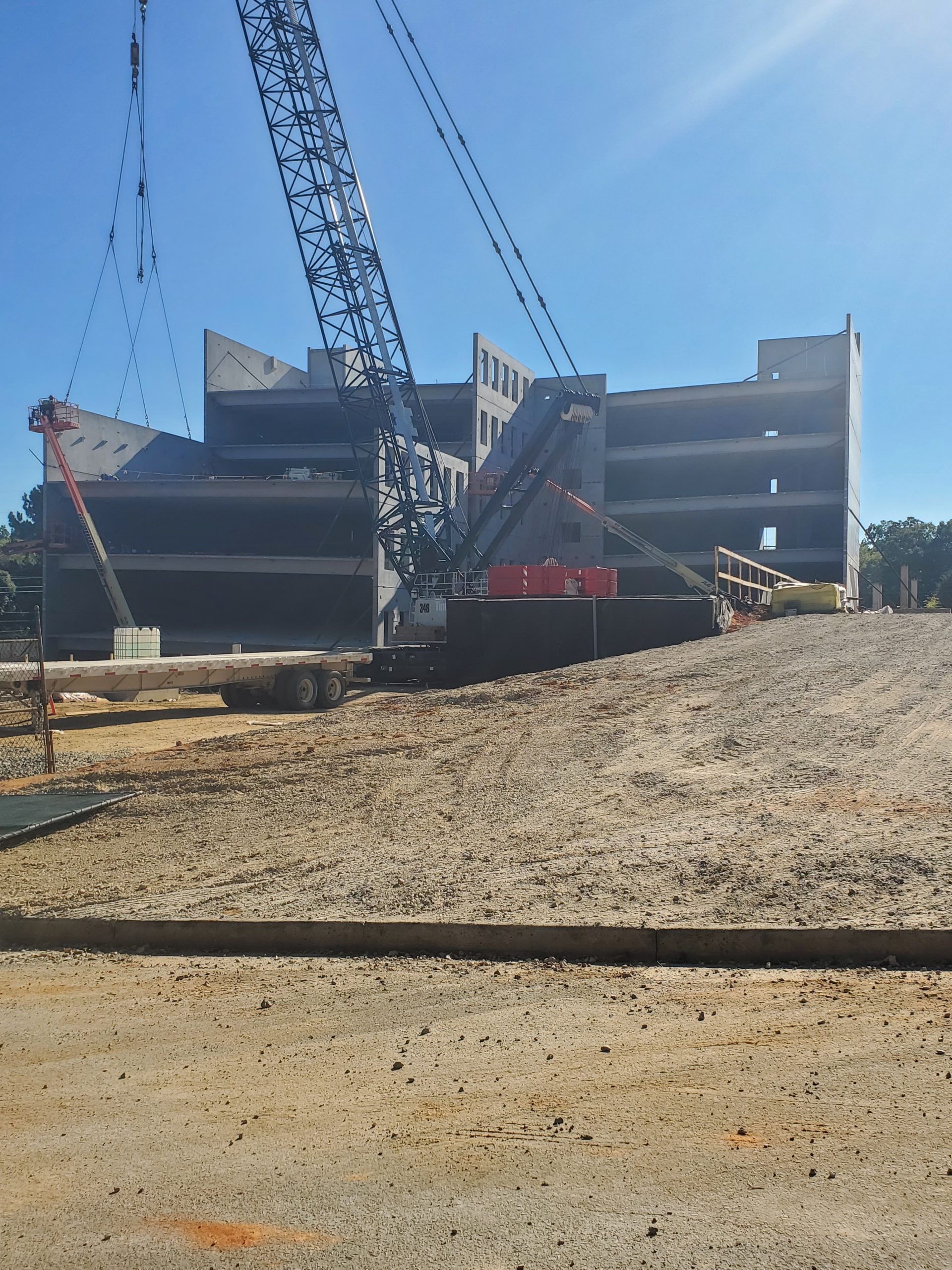
Cause * During lifting * During Transportation * During Erection * After erection & slab pouring Problem * where the cracking of panel further affected the waterproofing by damaging the internal stud walls of the building. * Reinforcement getting Weak * If any interior work will damage due to the weather proof issue. Remedies * Get concentrate those location & intimate to reinforce team for additional reinforcement * Insist to follow the Guidelines from the engineering team * Insist Factory to concern the reinforcement for the specific openings * Insist Factory & Erection Crew to Follow the standards & guide line when the lifting from the store, during transport & installation the panel * During transportation take care all panels sitting on ‘A’ frame to be vertically supported on 2 points & if any additional support should only be for lateral purposes. Insist to follow the transportation guidelines * The Grouting must be taken care on time for the panel with openings Coordinators to advise if any special cases if needed.
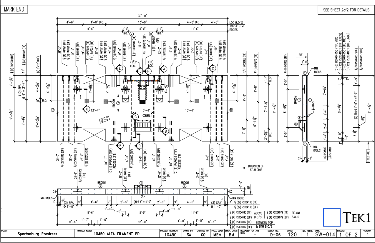
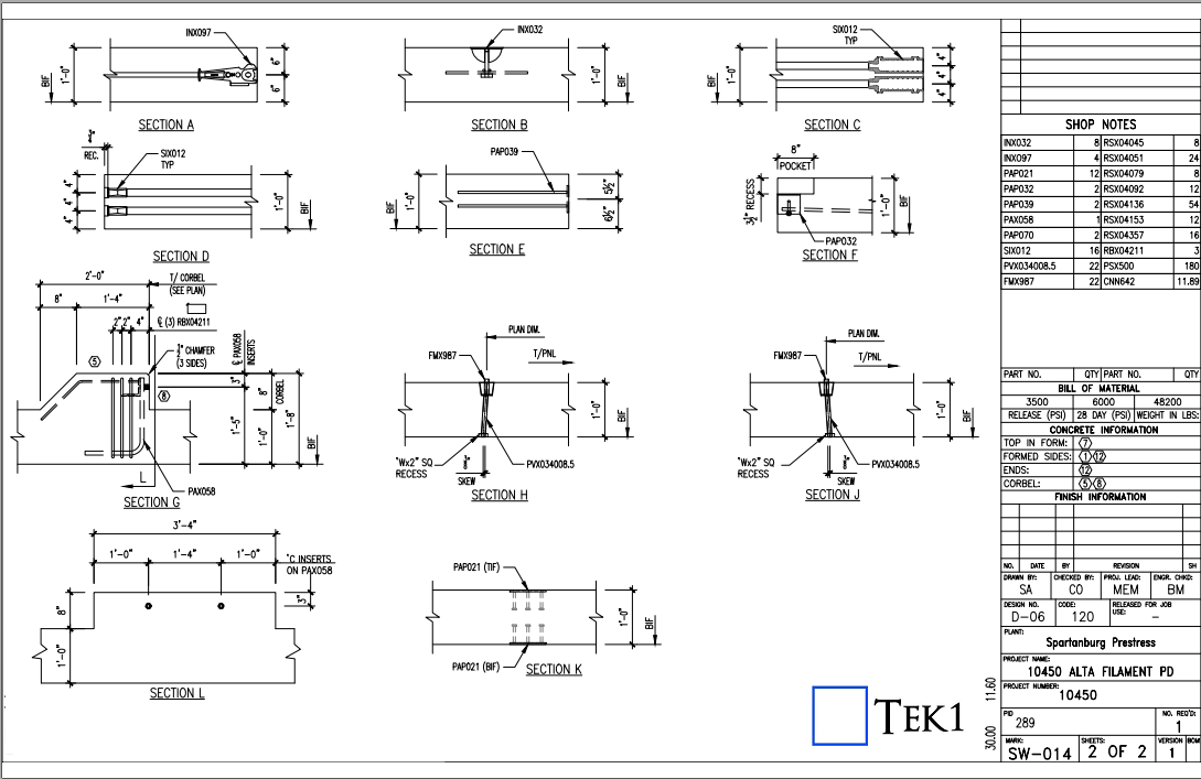
The important things to be considered in lift shop drawings for precast is listed below:
Core Setout.
Door Opening.
Recess at the bottom of lift door.
Landing Call Buttons penetrations.
Controller Box Penetrations.
Service Penetrations and internal platform box.
Lifting Eye Placements & capacity.
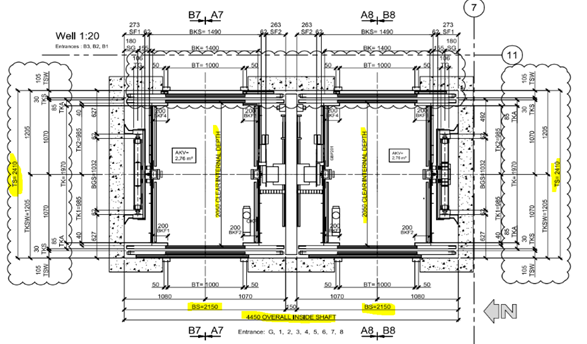
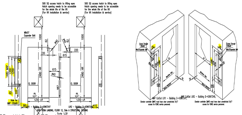
1. CORE SETOUT:
Lift Core Panels Setout in Concrete plan and structural plan should match with lift core details.
If any thickness of panels change keep inside dimensions unchanged, because inside dimensions are dictated by lift manufacturer’s drawings. Panels thickness change must affect only the outside dimensions of lift core.
Propping method – Lift Cores are generally erected first. Higher level slab may not have been poured when lift core goes up. Hence propping of lift core need to have some special attention.
2. DOOR OPENING:
The door opening width and height of lift in lift drawing should match with architect and structural drawings.
Make sure that the height of lift door opening in lift drawing are measured from FFL or SSL.
Minimum Header height should maintained Discuss with interested parities if there any doubt.
Always consider the RL’s difference between FFL and SSL while the opening height are finalized. FFL and SSL are usually different
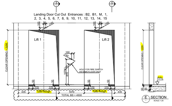
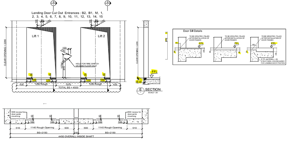
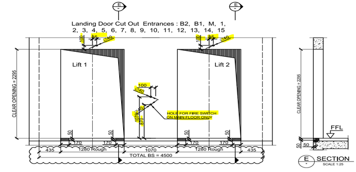
3.RECESS AT THE BOTTOM OF LIFT DOOR:
The recess at the bottom of lift door (as per door sill detail) is provided for door frame installation. Make sure we take this into consideration
The door sill details are not same for all projects we need to confirm the depth and width of recess at the bottom of lift door before start the detailing.
If the door sill height recess is wrongly provided (i.e. Measured from SSL instead of FFL) then there will be a problem in installation of lift door frame.
The provided recess depth should start from the end of clear opening of lift door.
Make sure that the Door sill details provided in lift drawings are measured from FFL or SSL.
4. LANDING CALL BUTTONS PENETRATIONS:
Penetrations for landing call buttons, fire switch and other electrical purpose are to be placed as per lift manufacturer’s drawings.
First confirm the view direction of lift drawing (viewed from landing i.e. Outside) and precast Setout. It will clear the location of the lift call buttons and other penetrations.
Ensure the height of penetrations provided in lift drawings are measured from FFL or SSL.
There will be penetrations of different diameter according to its purpose i.e. call buttons, electrical, fire switch etc. so concentrate more on size and location of penetration while detailing.
Penetration locations and size may vary according to the respective floor entrances so refer the details from correct floor entrance which is given in lift drawings.
5.CONTROLLER BOX PENETRATIONS:
Controller box may need a recess or in some cases could be a penetration.
Ensure the location of the control box from the panel edge, we need to maintain the sufficient gap from the edge of the panel.
Ensure the sufficient cover from reinforcement with the penetrations
6. SERVICE PENETRATIONS AND INTERNAL PLATFORM BOX:
Ensure the Hatch opening / exhaust opening need to be accessible for the whole lift for installation & service.
In some case there will be an internal recess requirement to allow for attaching temporary platforms inside the lift for servicing the lift. Make sure these recesses are same RL and opposite.
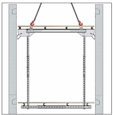
7. LIFTING EYE PLACEMENTS & CAPACITY.:
For the whole lift is closed by 2 types of lids One by cast-insitu lid and another by precast lid. If we have the precast lid, we need to consider the following things
Connection between the vertical precast & lid
Slope for the water drain
Finish of the face of the lid
Lifting Eye & Hooks for the Lift car & accessories fixing
Ensure the Capacity & size of the Hooks from the lift design.
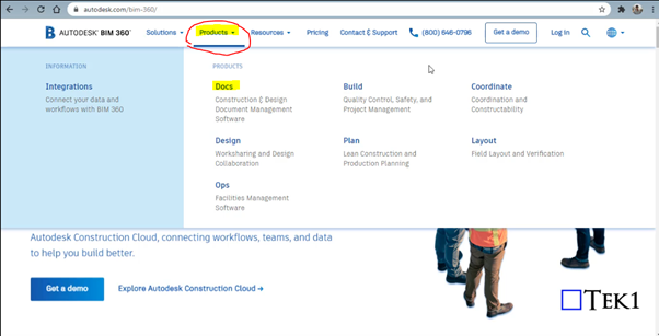
Bim 360 is Construction project management software created by Autodesk. The main intent of using Bim 360 Docs will resolve the following thing
The project status with its workflow with project time frame can be easily tracked by every consultant and organization assigned.
It helps to access the different file formats directly online instead of installing the particular software required
The error can be sorted and make the decision handling by solving the RFI raised to the concerned consultant which can be reviewed and easily sorted by accessing the file / Model directly
Anytime and anywhere access can be easily attained for the projects and their files
The mark-ups review provided by the consultant for the submitted documents can be reviewed and fixed easily
The file can be Access easily frim anytime and anywhere just by login to the Bim 360 in Browser or in mobile
It will make it simple in the documentation handling especially on the revised drawings and tracking the previous submittals history also.
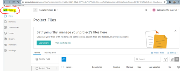
Steps for Creating Project in Bim 360 Docs (Before these steps, log in to the Autodesk account you created in the Bim 360 and select the docs. Click “try now” after that you will see the images shown below
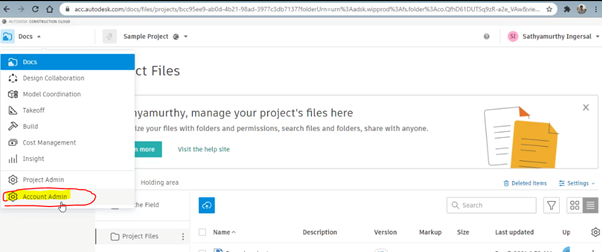
Step 1: Select the “Docs” Dropdown box on the top left corner of the Bim 360 Docs
Step 2: Click on the Account Admin to create a new project
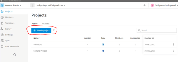
Step 3: Click on to “ Create Project”
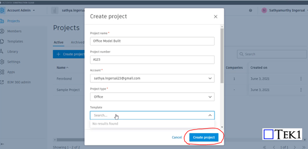
Step 4: Fill the Project Details and Particulars with your Autodesk Email ID and click Create Project
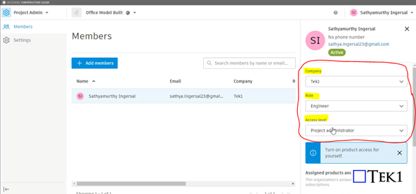
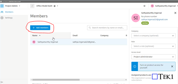
Step 5: Provide your information such as role, access level, and organization on the right-hand side
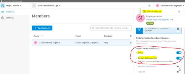
Step 6: Please Turn on the products to be used by moving the scroll down. So that Turned on feature can be accessed as shown in Step 10
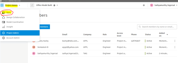
Step 7: Click on to Add member to assign the members who are going to involve and access the files in this project
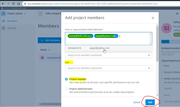
Step 8: Assign the members by adding their Autodesk email with organization name and their role and select as project member and click Add
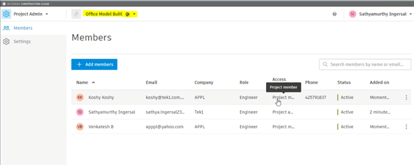
Step 9: After adding the member you can see their active status and details under the project we assigned
Step 10: As we turned on the following highlighted things in step 6. So that now we can access the following by Selecting the Dropdown and click on the docs to upload the file
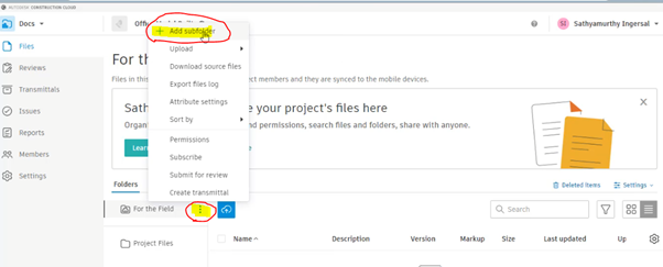
Step 11: To create Subfoler and folder click on to the highlighted below and select Add subfolder
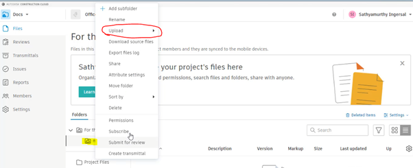
Step 12: After creating and naming the folder right-click to it and click on the upload and file. then drag the file and start upload
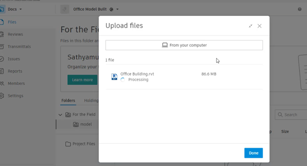
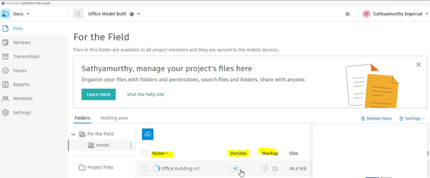
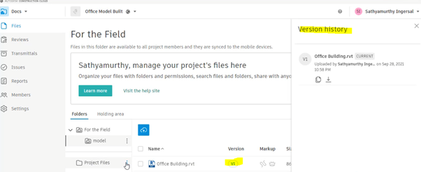
Step 13: The file with its details and version, Mark-ups status will be displayed once the above steps are done
By clicking on to version you can review the history of the file from start to upload till revised. The file model can be review online itself by clicking on Filename
This video explains how to create Layer property filters and layer Group filters for Autocad. nano cad should be same. My nanocad Lic is not yet installed. Using layer filters is a great help to manage your cad files.
Help on Autocad commands are right there at the command line. However, too many times new users ask questions. Not just new users, experienced users as well get used to some way of working and stay there without checking out the full documentation. This video show where the command is available