Category: Projects

  • Tekla Part Mark Issue with 1° Rotated Slotted Holes

    Tekla Part Mark Issue with 1° Rotated Slotted Holes

    This article explains the Tekla Part Mark Issue with 1° Rotated Slotted Holes and provides a practical solution.

    One common issue in Tekla Structures is assigning the same part mark to different-looking plates.

    This occurs when two plates have identical dimensions, thickness, material, and slotted hole size.

    One plate contains a standard horizontal slotted hole.

    The other plate has the same slot rotated by only 1°.

    Although the slot orientations differ, Tekla evaluates both plates using its 1 mm geometry tolerance.

    The 1° rotation creates a geometric difference within this tolerance.

    Therefore, Tekla considers both plates identical.

    As a result, Tekla automatically assigns the same part mark.

    The Tekla Part Mark Issue with 1° Rotated Slotted Holes occurs because Tekla compares geometry using its default tolerance.
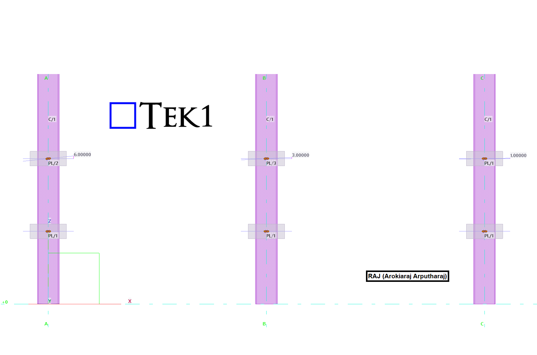
    Please see the attached snapshot. Tekla is assigning different part marks to plates even though the only difference is that the slots are rotated by 1°. This results in additional time and cost for both the detailing and fabrication processes.

    This behavior can create confusion during detailing and fabrication.

    Detailers may expect different part marks because the slot directions are different.

    Fabricators may struggle to identify the correct plate for each connection.

    The issue can also affect CNC data generation.

    Quality inspections may become more difficult.

    Site assembly can also be affected when slot orientation is important.

    Solution to Resolve the Part Mark issue Between Plates with Horizontal Slots and 1° Rotated Slotted Holes

    Understanding the Tekla Part Mark Issue with 1° Rotated Slotted Holes helps detailers avoid unnecessary part variations.

    A simple solution is to standardize the slot geometry.

    Avoid creating separate plates with slightly rotated slots.

    Instead, use a larger diameter horizontal slot for all similar plates.

    The larger diameter slot accommodates the required installation tolerance for the 1° Rotated Slotted Holes.

    Every similar plate then shares the same geometry.

    All plates also receive the same part mark by design.

    This approach removes unnecessary part variations.

    It also maintains the required functionality and installation fit.

    By following this method, you can permanently resolve the Tekla Part Mark Issue with 1° Rotated Slotted Holes.
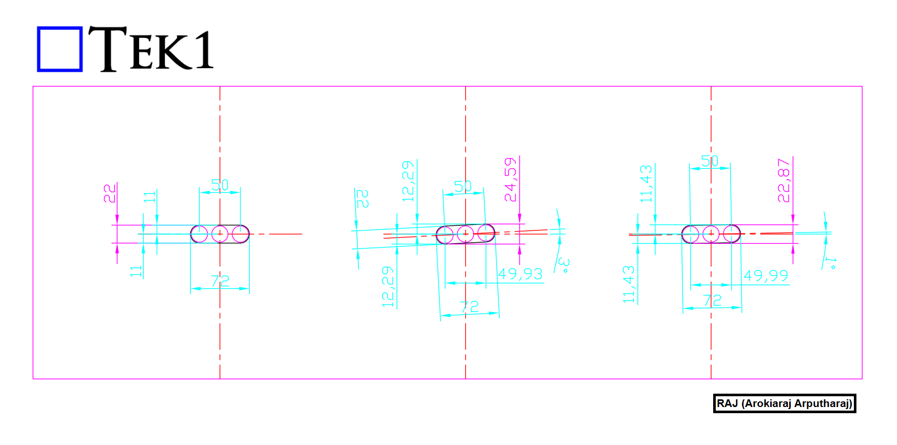
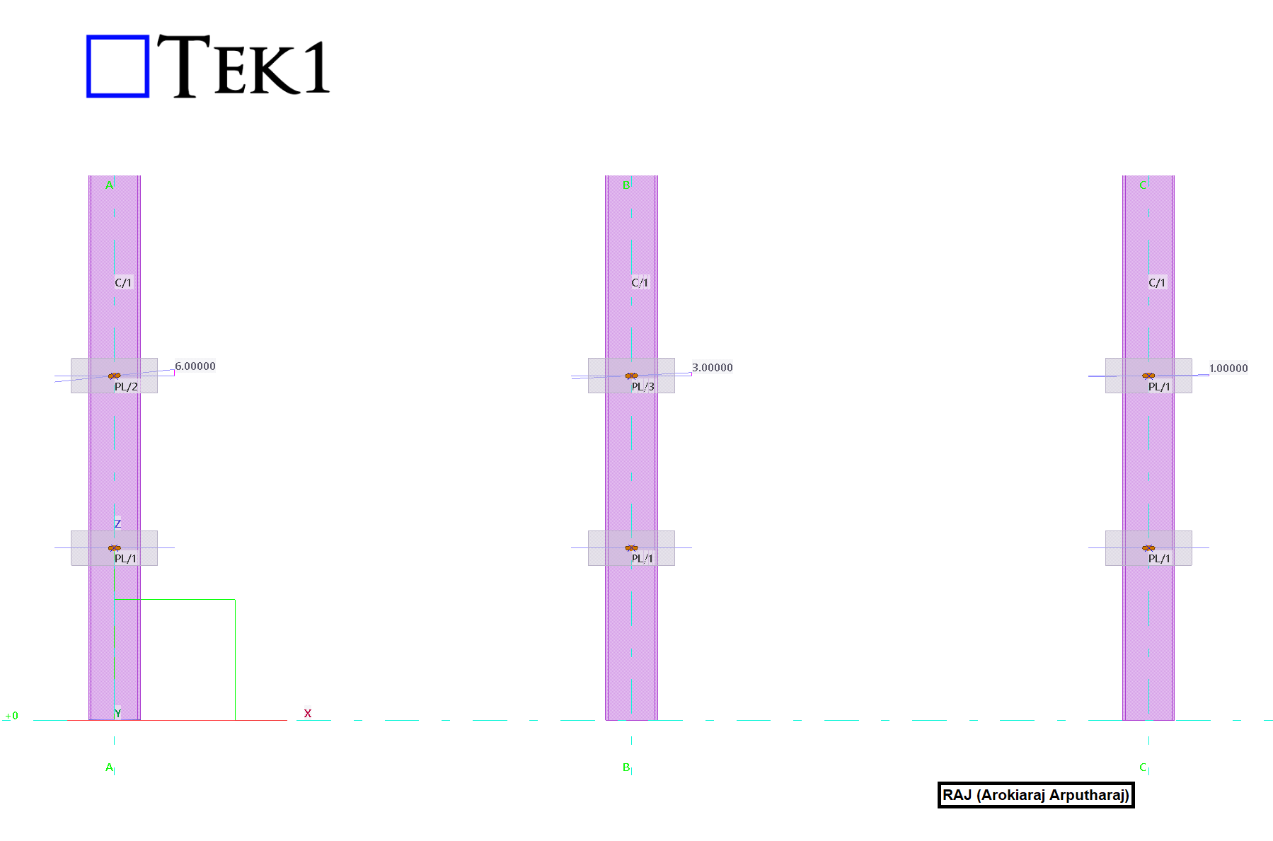
    Please see the attached snapshot. When comparing the overall height of the standard horizontal slot with the slot rotated by 1°, there is only a 1 mm difference. Therefore, we can increase the standard horizontal slot diameter by 1 mm so that the same slot size can be used for both situations. This will allow us to assign a single part mark to all identical plates, simplifying both the detailing and fabrication processes.

    Standardizing slotted holes provides several additional benefits.

    It reduces the number of unique parts in the model.

    It simplifies detailing and drawing production.

    Fabrication becomes easier and more consistent.

    CNC programming also becomes simpler.

    The risk of manufacturing errors is reduced.

    Assembly errors are less likely to occur.

    Inventory management also becomes easier.

    Fewer unique plate types need to be tracked.

    This method is considered a best practice whenever extra slot tolerance is acceptable.

    Always verify that the larger diameter slot meets project requirements.

    Confirm compliance with engineering specifications before implementation.

    Also ensure the connection design remains unchanged.

    Using standardized slots creates cleaner Tekla models.

    It improves fabrication efficiency

    and reduces unnecessary detailing work.

    also eliminates part mark conflicts caused by minor slot rotations.

    By following this method, you can permanently resolve the Tekla Part Mark Issue with 1° Rotated Slotted Holes.

    Key Benefits

    • Eliminates duplicate part mark issues.
    • Standardizes plate geometry and fabrication.
    • Reduces the number of unique plate types.
    • Simplifies detailing and CNC programming.
    • Improves manufacturing efficiency.
    • Prevents confusion during production and assembly.
    • Helps maintain a cleaner and more consistent Tekla model.

    We hope this guide helps you solve the Tekla Part Mark Issue with 1° Rotated Slotted Holes in your future Tekla projects.
    Read more Tekla tips and technical guides on our Blog

  • Park Street-L7 Framing

    Park Street-L7 Framing

    Expert Detailing of high end Residential Buildings

    Longstanding Client puts their faith again in Tek1 – and we deliver with NIL errors and smooth project management.

    (more…)

    Expert Detailing of high end Residential Buildings

    Longstanding Client puts their faith again in Tek1 – and we deliver with NIL errors and smooth project management.

    (more…)

    Expert Detailing of high end Residential Buildings

    Longstanding Client puts their faith again in Tek1 – and we deliver with NIL errors and smooth project management.

    (more…)
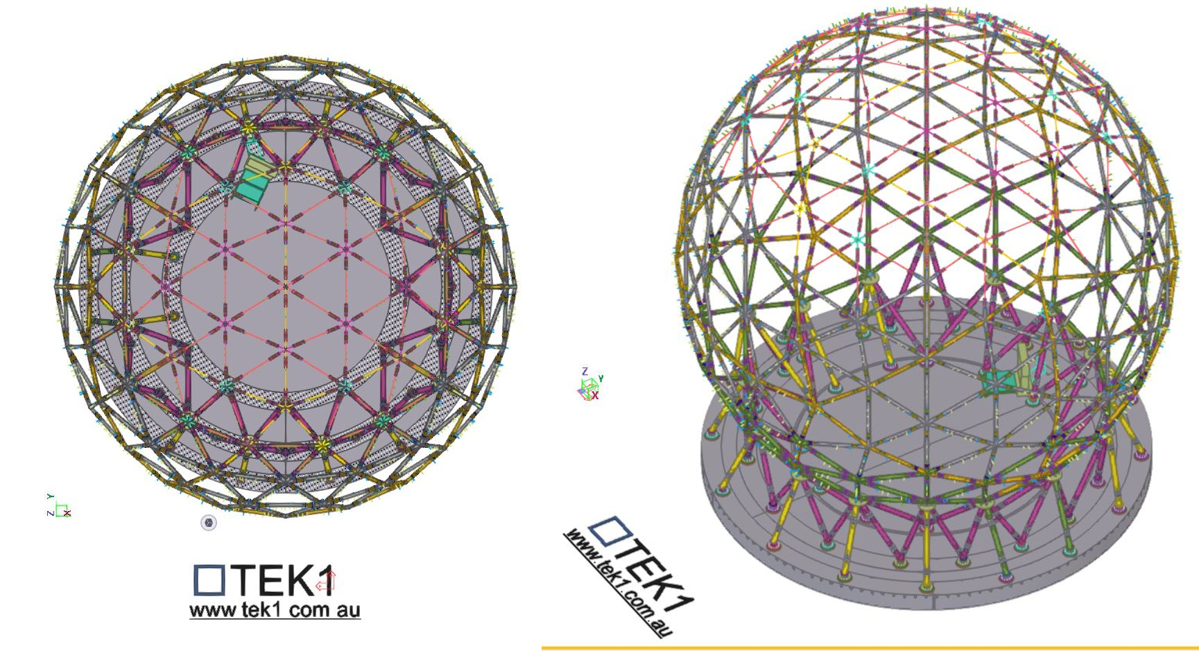
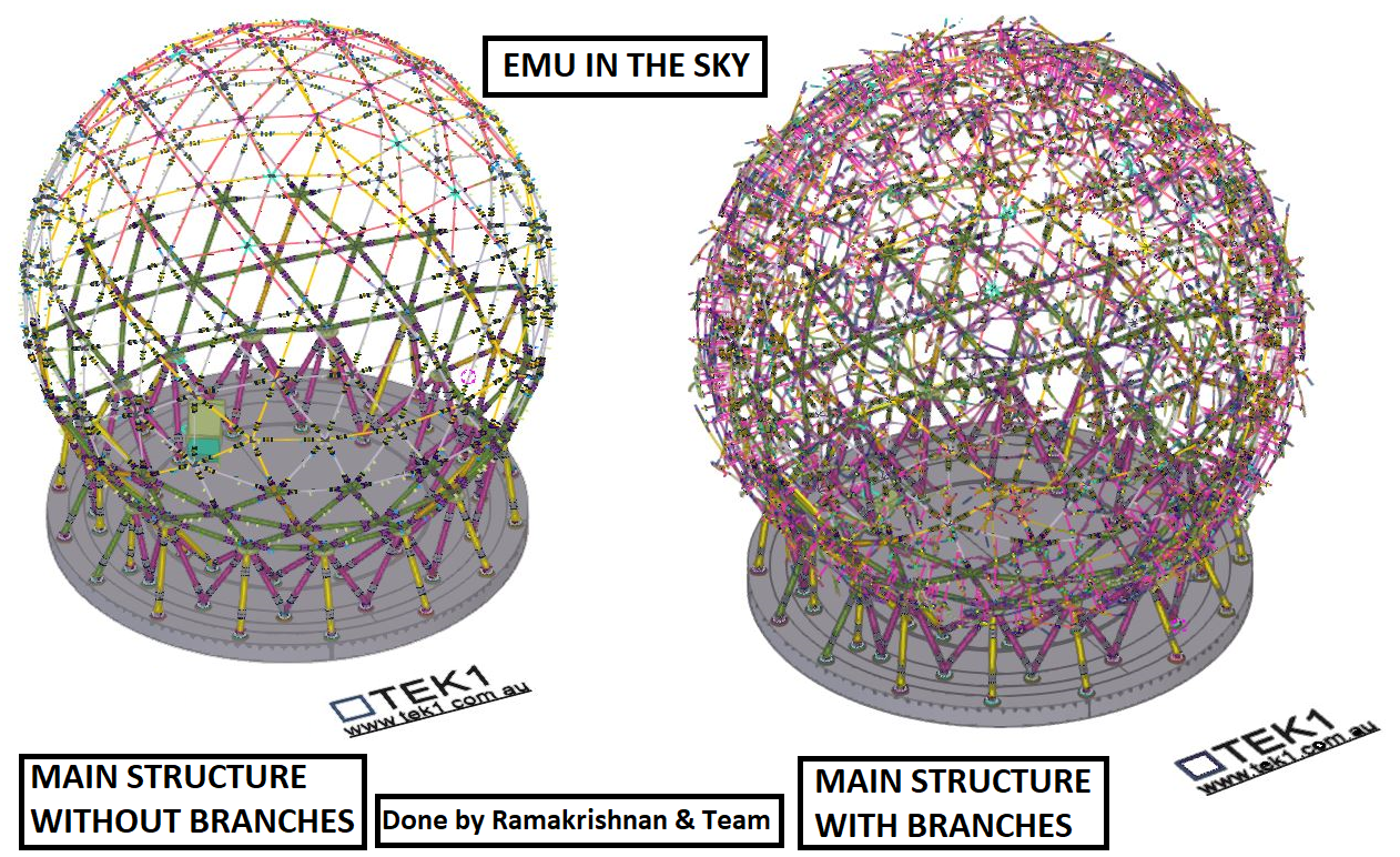
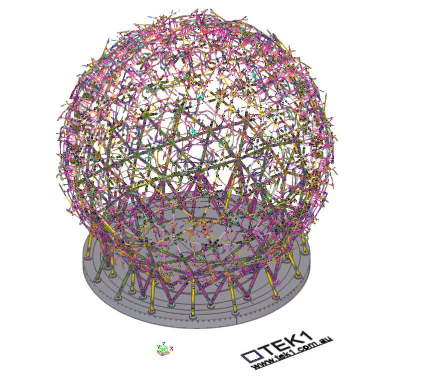
  • Complex Tekla Model – Emu in the Sky

    Complex Tekla Model – Emu in the Sky

    The Client

    Chess Industries was the client here. We were ably guided by Mohan and Mike on this project. We also put in our two cents worth cutting costs, eleminating problems before they crystallized.

    Jigs

    The jigs and tooling required was thought about even before we started. We have proposed certain tooling, which Chess have made some slight modifications. The tooling was part of the modelling, which simplified the fabrication of the entire job.

    Connection Design

    We have taken the concept design. Identified problems with the design which could make fabrication erection extremely difficult. Chalked out certain proposals. Mohan and Mike expanded on our ideas came out with a proposal which all were happy to work with. The result is easy fabrication and assembly.

    Tekla Model

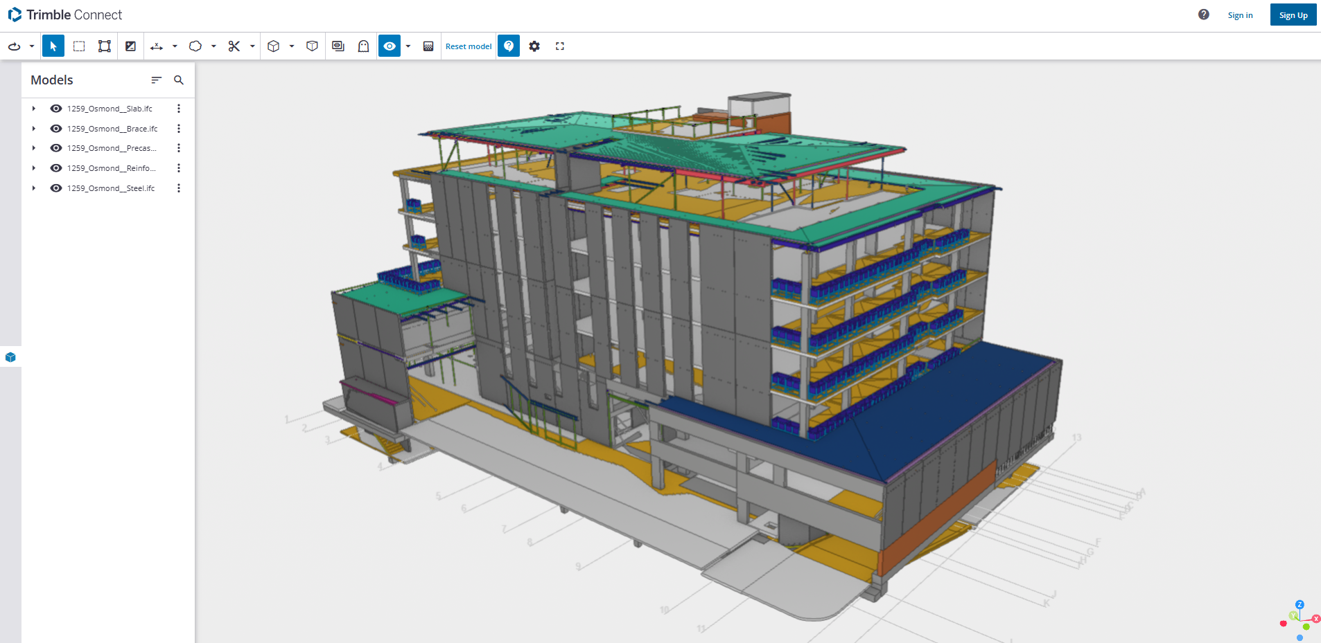
    You can view the trimble connect Tekla Model at this link

    Emu in the Sky

  • Steel Detailing Projects | Melbourne | Sydney | WA

    Steel Detailing Projects | Melbourne | Sydney | WA

    • Prefab concrete industrial unit -South grafton

    • Steel Detailing Tips – Things to Watch out for when Steel Interfaces with Precast Panels

    • Steel Detailing |NSW|AUS|

      Accessible Amenities

    • Steel Detailing |VIC|AUS|

      Show Room Extension

  • Ringwood Fire Station

    Ringwood Fire Station

  • pedestrian over pass

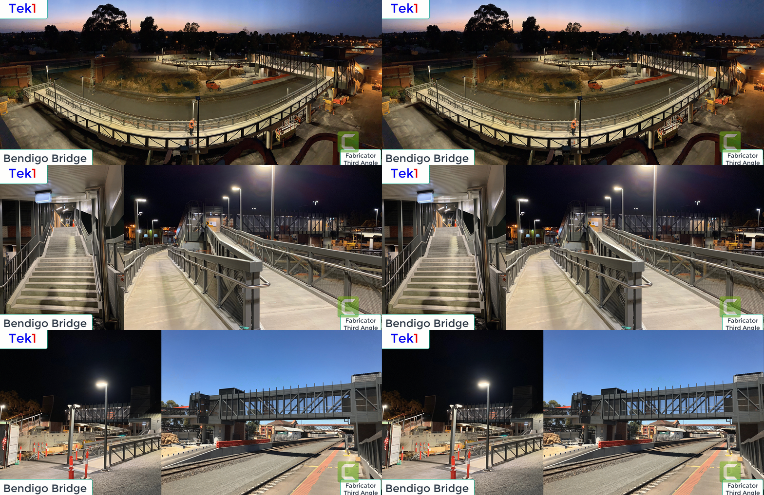
    Bendigo Pedestrian over pass

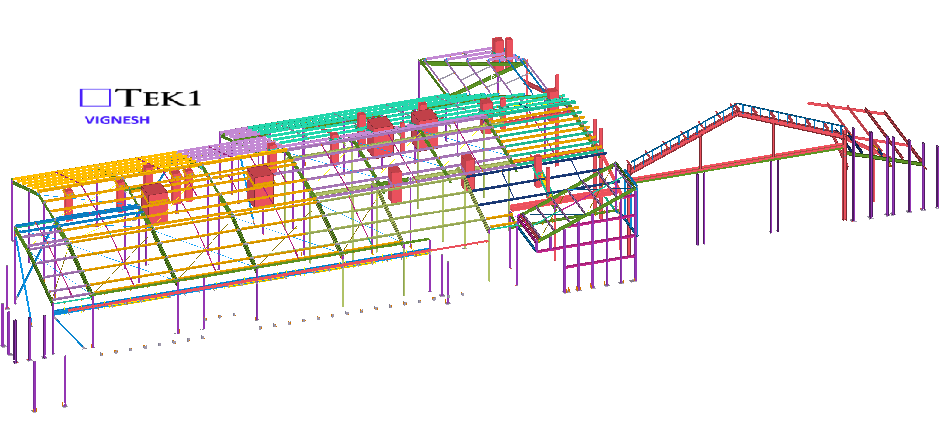
    Just revisiting some old projects. This project was fabricated by Third angle, Detailed by Tek1. One of the early pedestrian bridges detailed by Tek1.

    Many more followed after this.

    Bendigo pedestrian Bridge
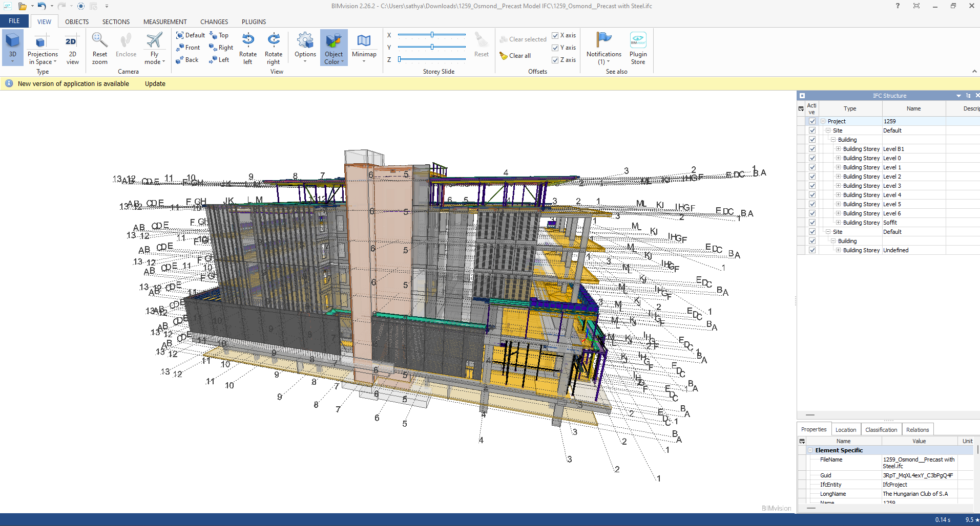
  • TYPES OF MODEL VIEWERS FORMAT , PURPOSE AND ITS BENFITS

    A. IFC Mode

    Industry Foundation Classes (IFC) is an open file format developed by Building Smart Alliance. It is an international data exchange standard for exchanging building information across different software platforms. An IFC Model is just a model of a building or a construction project with all geometric, structural, and semantic information.

    Key Features of IFC Models:

    • Open Standard: IFC is vendor-independent, i.e., any software that supports it can be accessed, without regard for the vendor.
    • Static Data Exchange: It is mostly utilized for data exchange between software tools, data import, and export. For instance, an architect can create a model using Revit and export it as an IFC file, which can then be imported into structural engineering software like Tekla or SAP2000.
    • Limitation of Real-Time Coordination: IFC files are representations of the model at a specific moment. Changes in one application are not duplicated in another except where the file is re-exported and re-imported.
    • Use Cases:
    • Exchange of models between stakeholders with various software.
    • Ensuring interoperability in interdisciplinary projects (e.g., construction, engineering, and architecture).

    Advantages of IFC Models:

    • Encourages collaboration and interoperability in BIM workflows.
    • Reduces errors by making sure all stakeholders are working from the same information.
    • Allows clash detection and coordination between different disciplines.

    B.  Live Link Model Viewer

                      A Live Link Model Viewer is software that enables real-time sharing and visualization of BIM models on various software platforms. Unlike IFC models, which are pre-exported static files, a Live Link Model Viewer enables multiple users to work on the same model at the same time using different software programs. Common examples of Live Link Model Viewers are:

    Revit Live: A cloud-based collaboration platform by Autodesk.

    Trimble Connect: A BIM data management and sharing tool.

    Key Features of Live Link Model Viewers:

    1. Real-Time Collaboration: One software application’s changes are reflected immediately in the model viewer and other linked applications.
    • Dynamic Data Sharing: Unlike static IFC files, Live Link Model Viewers offer dynamic, real-time linking between software applications.
    • Multi-User Collaboration: Multiple stakeholders can view and edit one model at the same time even though they are in different software.
    • Use Cases:
    • Real-time collaboration among architects, engineers, and contractors.
    • Collaborative design review and clash detection.
    • Smooth communication between teams working on different software platforms.

    Advantages of Live Link Model Viewer Benefits:

    • Make collaboration more effective and faster.
    • Eliminate the need for repeated file imports and exports.
    • Enhance accuracy by getting the entire team to work on the current version of the model.

  • How TEK1 Solved the Complicated Star Node Puzzle in Great EMU in the Sky

    How TEK1 Solved the Complicated Star Node Puzzle in Great EMU in the Sky

    At TEK1, we believe great detailing is more than just precision—it’s about understanding real-world challenges and turning complexity into clarity.

    The Challenge

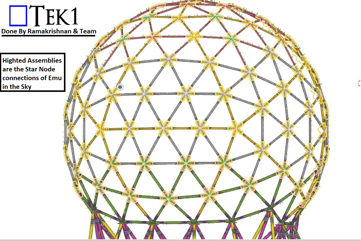
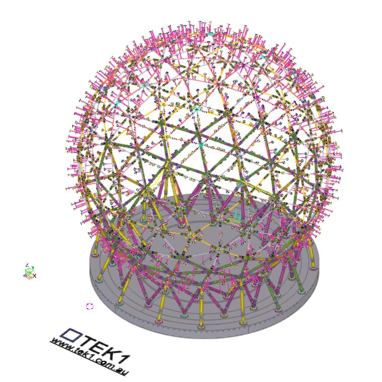
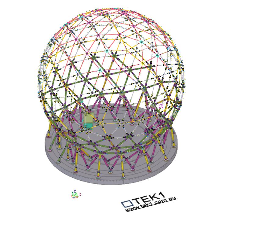
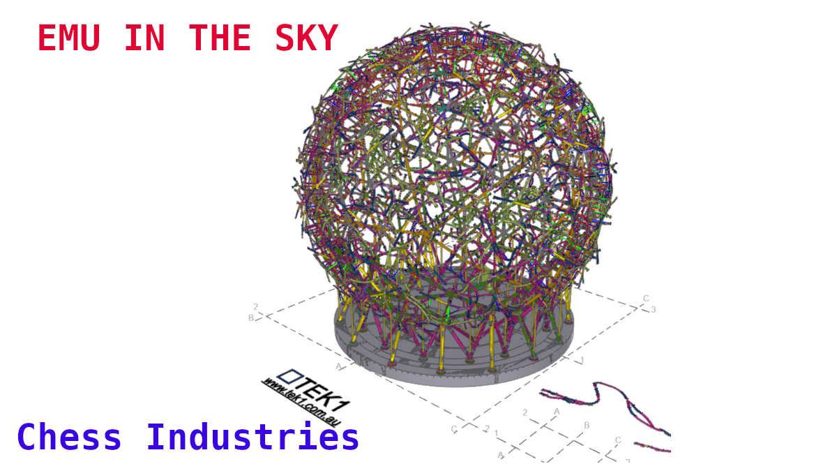
    The Great EMU in the Sky project presented one of the most unique and technically demanding structures we’ve ever worked on—a 30-metre-wide globe made up of 128 intricate “star nodes” connecting the bracing members.

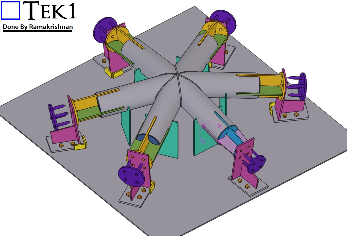
    These nodes weren’t ordinary joints. Each featured 5 or 6 connection points and came in three different CHS sizes, with every arm set at unique, non-repeating angles.

    For the fabrication team, this posed a significant challenge:

    • 128 Complex Star Nodes, each with custom angles
    • Inconsistent geometries
    • Time-consuming and difficult to fabricate accurately

    Even with precise 3D modelling, the practicality of fabrication was proving to be a serious bottleneck. Something had to change.

    The Turning Point

    That’s when TEK1 took the initiative.

    Rather than simply delivering a model and walking away, we engaged directly with the fabricator to understand the issue from their perspective. We realized that even the most accurate detailing wasn’t enough—what the team needed was smarter, fabrication-friendly solutions.

    The Solution

    Our detailing team re-engineered how the star nodes were documented, presented, and ultimately fabricated. Key solutions included:

    • Custom fabrication jig design: We developed a dedicated jig that allowed star nodes to be fabricated with greater ease and precision, regardless of the angle configuration.
    • Standardized node sub-groups: We grouped similar nodes together to reduce variation and streamline production.
    • Detailed templates: For common angle types, we provided accurate templates to guide fabrication.
    • Visual fabrication aids: Clear drawings showing exact cuts, welds, and orientations for every node.

    The Result

    • Faster fabrication times
    • 🎯 Improved accuracy and alignment
    • 🔁 Reduced rework and error rates
    • 🤝 Stronger collaboration between design and workshop teams

    Most importantly, the fabricators were able to work with confidence, knowing each node would come together exactly as intended.

    Taking Detailing to the Next Level

    This project reinforced one of TEK1’s core values: true excellence in detailing comes not just from precision—but from empathy. When we truly understand the needs of the people building the structure, we unlock practical, buildable solutions.

    The Great EMU in the Sky is more than a globe—it’s a powerful example of what happens when detailers and fabricators work together as one team.

    📢 Call to Action:

    🚀 Have a complex structure or fabrication challenge? Partner with TEK1—where technical expertise meets buildability.

  • TEK1 Brings the ‘Great Emu in the Sky’ Sculpture to Life for Sydney’s M12 Motorway

    TEK1 Brings the ‘Great Emu in the Sky’ Sculpture to Life for Sydney’s M12 Motorway

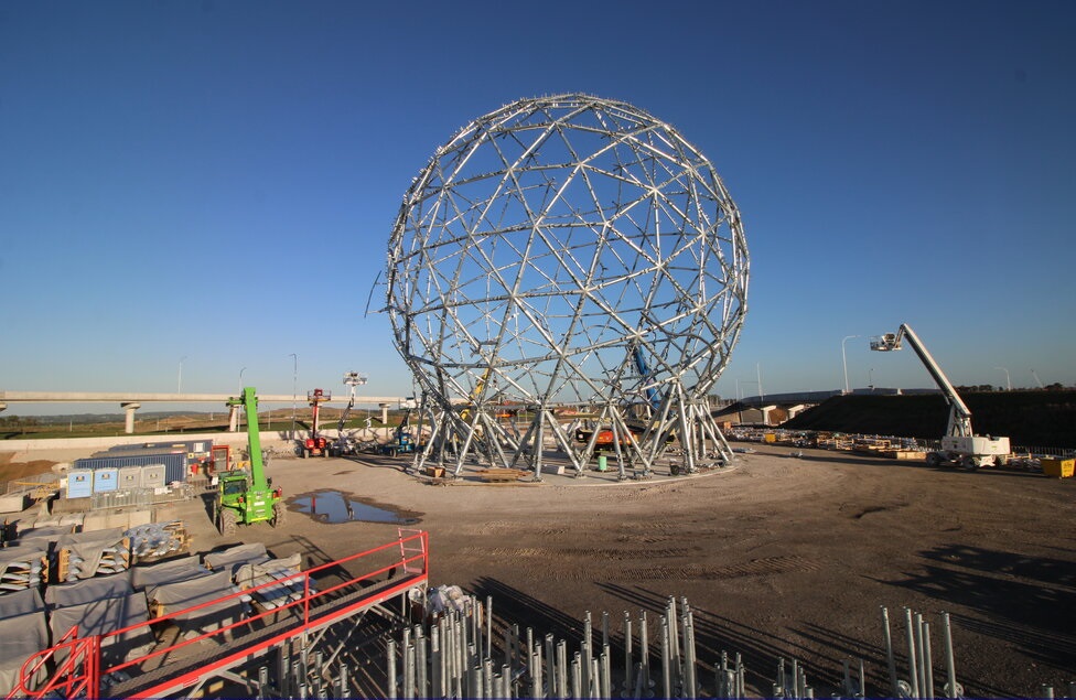
    TEK1 is proud to be part of an iconic project—the ‘Great Emu in the Sky’ sculpture, a monumental 30-meter-high emu nest that will stand as a cultural landmark along Sydney’s M12 Motorway.

    A Symbol of Dharug Heritage

    The peanic structure celebrates the Dharug Community’s sacred creation story of the Great Emu constellation.

    A Landmark Visible from Land & Sky

    Positioned for maximum visibility, the sculpture will be seen by:

    • Road users
    • Pedestrians
    • Sydney Metro passengers
    • Even planes approaching and departing Sydney Airport

    Blending Art, Culture & Engineering

    The steel artwork will take on different forms depending on the time of day and viewing angles:We look forward to seeing this one-of-a-kind sculpture take its place in Sydney’s landscape, honoring history while welcoming the future.

    • By day, it will resemble an emu nest, crafted from signature steel “sticks” that reflect the natural landscape and traditional materials of the Dharug people.
    • By night, it will illuminate and reveal two emu forms, visible only from certain perspectives—mirroring the Great Emu constellation as it shifts throughout the six Aboriginal seasons.

    TEK1’s Role in Detailing the Sculpture

    A lot of technical challenges were navigated to ensure that this complex structure, could be fabricated and erected, cheaply and efficient. We will document this on our blog if you’re interested.

    Please refer to the below video which represents the various stages of on-going erection