Dowel bars:
- Dowels are short straight steel bars and also cogged bars, used to provide mechanical or structural connection between two precast elements or in-situ to precast elements.
(Refer Fig.01)
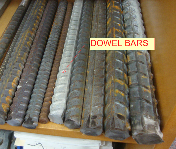
(Fig.01) Dowel bars
Purpose of Dowel bars:
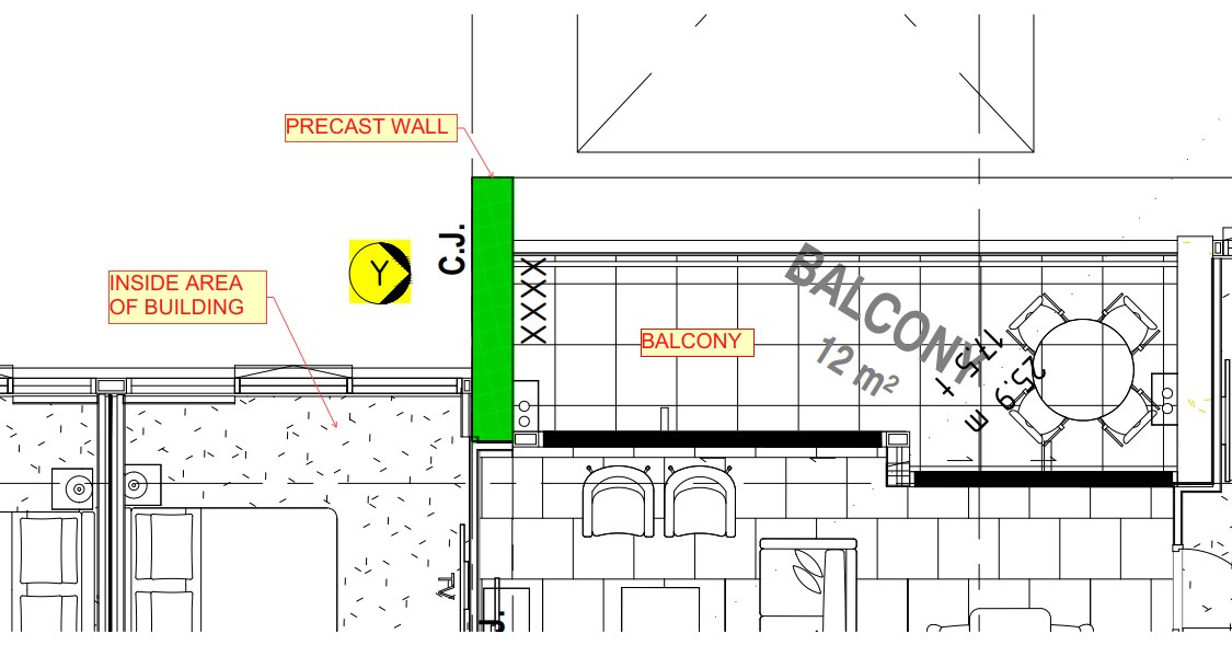
- Dowel bars used to maintain the horizontal and vertical alignments of slab and precast panel. (Ref Fig.02)
- Dowel bar connection used to transfer the loads between two concrete elements or two precast elements or precast to in-situ elements. (Refer Fig.03&04)
- Dowel bar is used to extend the structure easily with small drilling to insert the steel for the extension of the structure.
General details for Dowels:
- Dowel bar is a steel rods with spiral outer design. (Refer Fig.01)
- Used in all the locations where Grout tubes are required.
- Selection of Dowel based on Engineer requirement.
- Dowel can either be black finish or galvanized finish.
- Black finish for load bearing dowels and galvanized finish for NLB (non-load bearing) dowel. (It may be varied).
- Alternatively, bars connected into NMB splice sleeves can be used. Also, starter bars can be casted into panel.
- Plastic tube will be placed over upper half of dowel. And 20mm compressible cap will be placed over the top of the dowel bar for NLB (non-load bearing) portions whereas grouting material will cover the entire dowels for LB (Load bearing) conditions.
- Dowels must be positioned within Grout Tubes with minimum amount of clearance on precast walls or slabs.
Advantages:
- It is reducing the corner cracking.
- It will reduce joint faulting.
- Dowel bar is also used to reduce the deflection and stress.
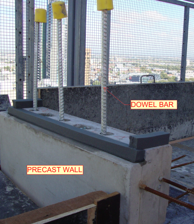 (Fig.02) Precast wall connection
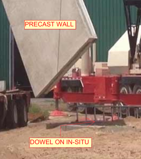 (Fig.03) – Precast to in-situ connection
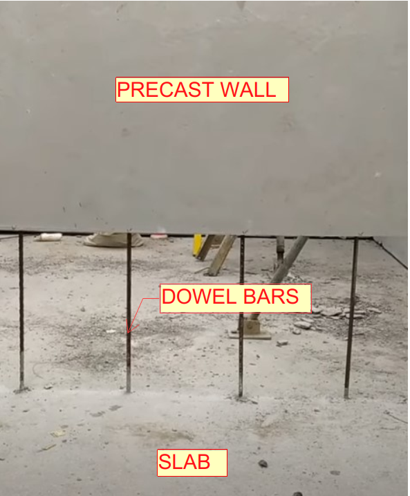 (Fig.04) – Precast to slab connection
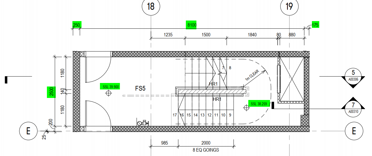
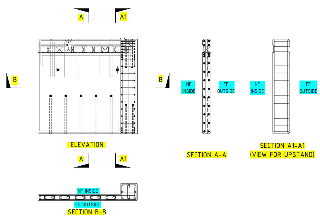
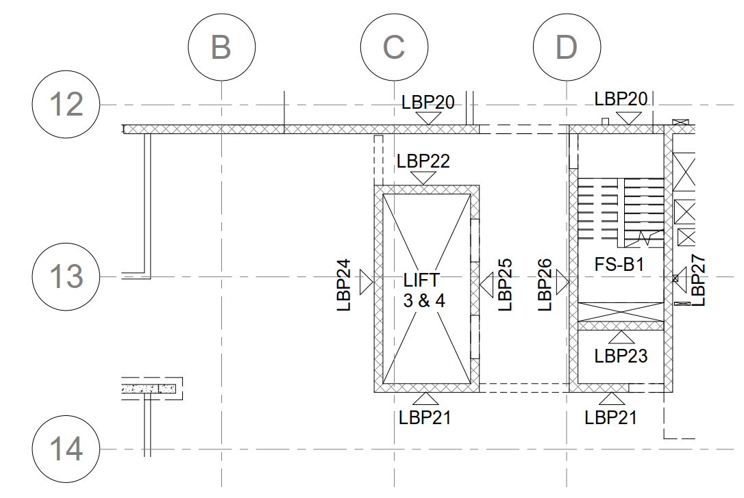 (Fig.01) SAMPLE CORE KEY PLAN
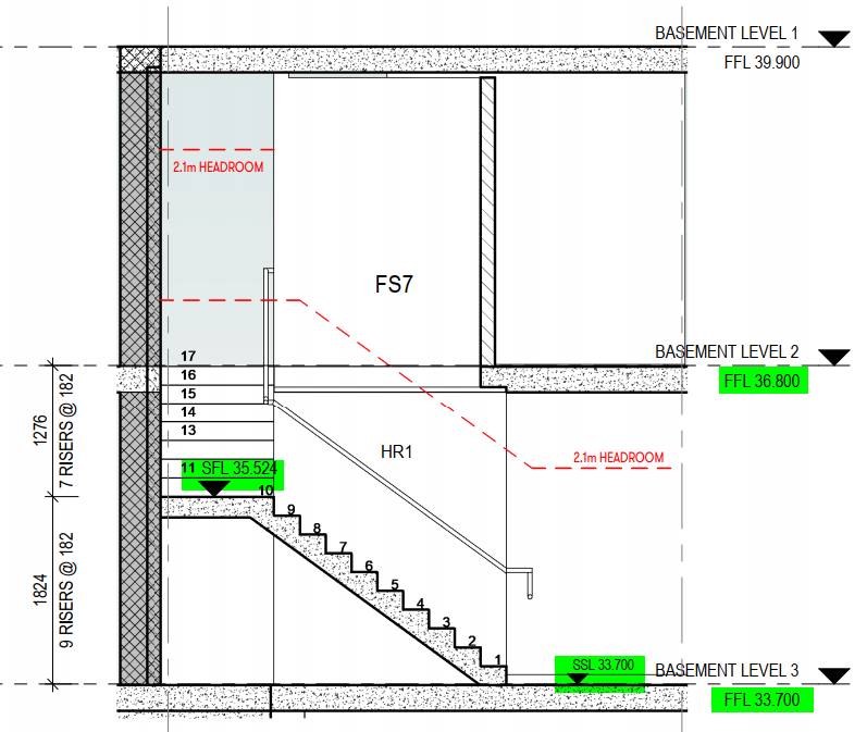
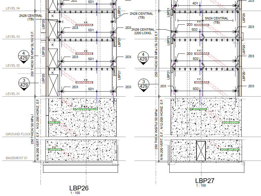 (Fig.02) SAMPLE CORE ELEVATION