Cloning of Assembly Drawings in Tekla is the Smartest Way to Improve Detailing Efficiency

In structural steel detailing, efficiency and accuracy are critical to delivering projects on time. As projects grow larger and more complex, detailers must find smarter ways to manage repetitive components and maintain consistency across drawings. One powerful feature that helps achieve this in Tekla Structures is Assembly Drawing Cloning.
Cloning assembly drawings is a highly effective method that allows detailers to duplicate an existing assembly drawing and apply it to similar assemblies within the model. Instead of creating drawings from scratch every time, detailers can reuse a well-configured drawing layout, saving significant time while maintaining uniform standards across the project.
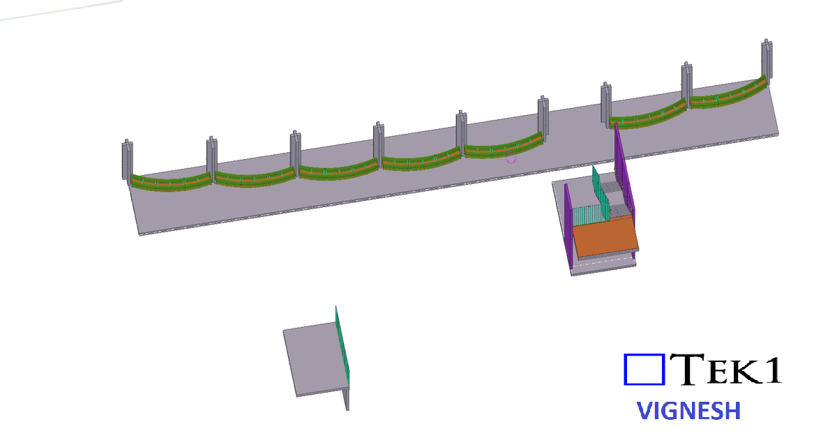
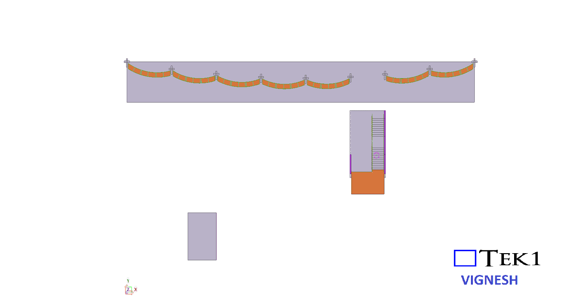
In steel structures, many assemblies such as beams, columns, bracing members, and connection components often share similar configurations. When these assemblies are modeled with comparable geometry and detailing requirements, cloning becomes an invaluable tool. By copying an existing drawing and adapting it automatically to another assembly, Tekla helps detailers maintain consistency in dimensions, views, marks, and annotations.
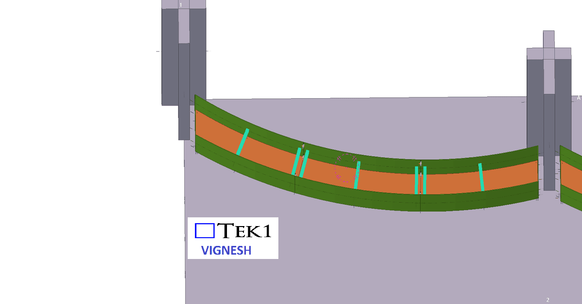
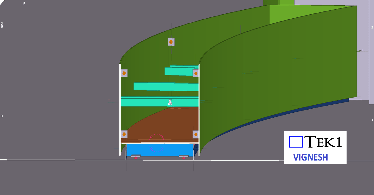
Another advantage of cloning is its ability to intelligently adapt to small variations between assemblies. Tekla automatically adjusts views, dimensions, and annotations to match the geometry of the new assembly. This allows detailers to reuse drawings even when there are minor differences in member length, hole positions, or connection details
Please refer to the video below, which elaborates on the cloning process and the working method in Tekla Structures