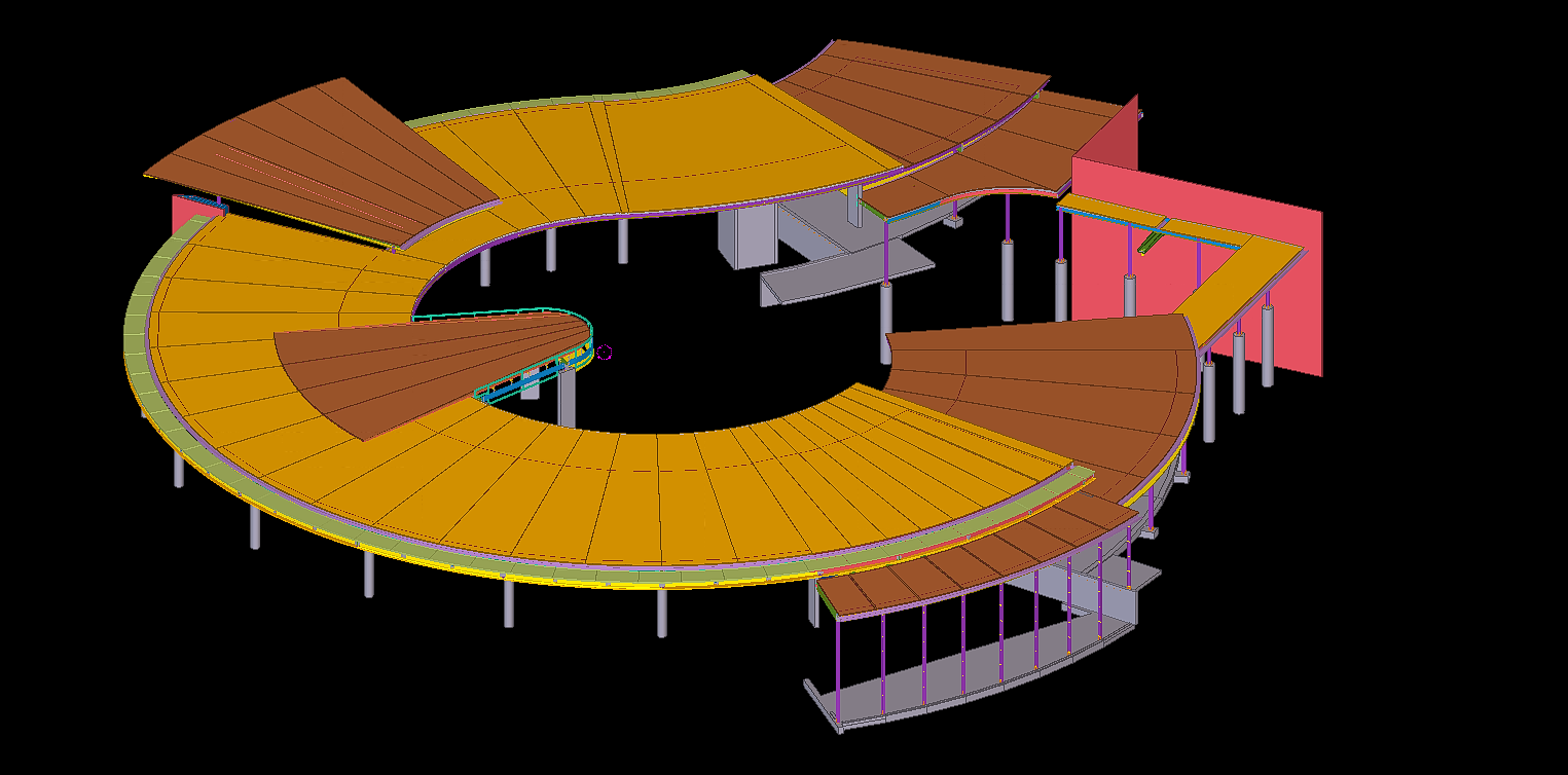
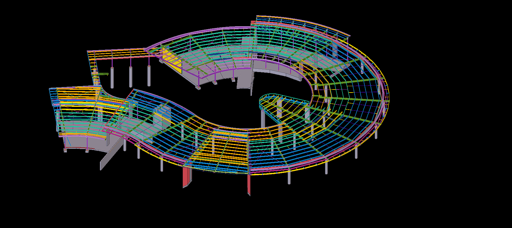
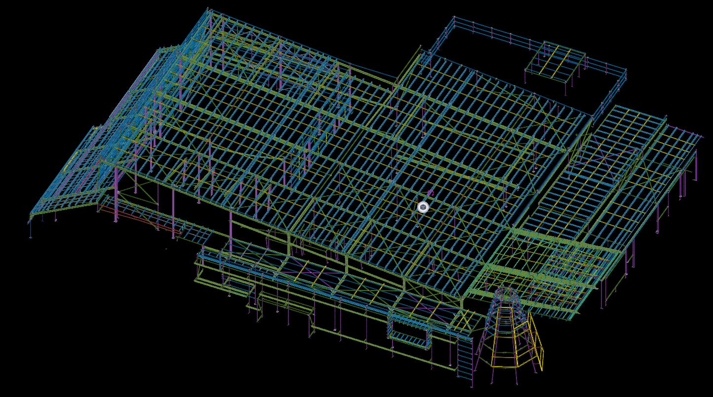
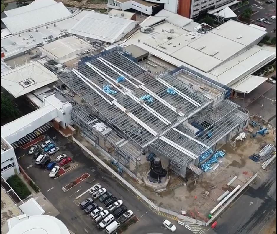
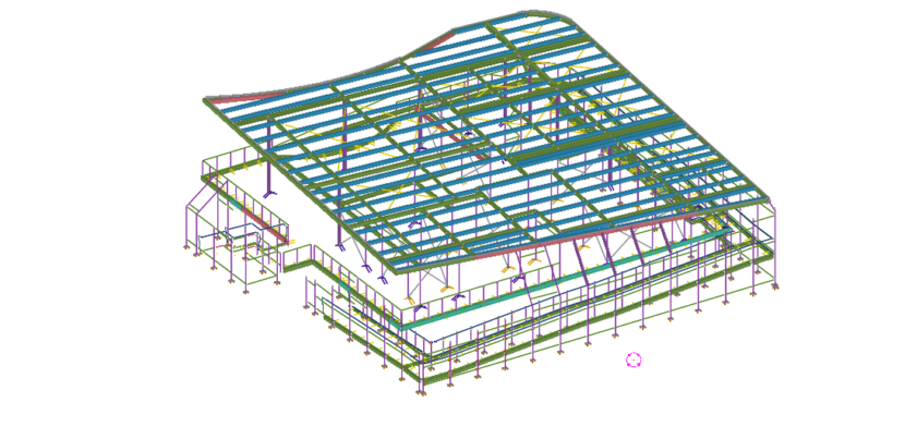
We are proud to be a part of the team in Macarthur Anglican School project. The tapered roofing, windows and cladding makes the steel work complex. Yet we are proud to say that we have done the job efficiently with client satisfaction.
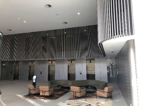
3D – Flyover of MacArthur Anglican SchoolSnip From TeklaSnip From Tekla – Main SteelSnip taken On-Site
Blog by Bharath – Tek1 Pvt Ltd. Visit www.tek1.com.au for further enquiries.
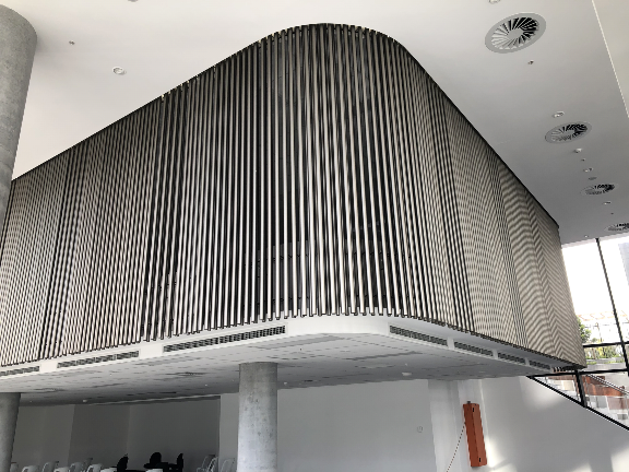
This is a complicated project, but it came through. Our Scope was Hanging Balustrade around the Ground Floor Lobby. We need to provide those balustrade in numerous panels. This requires much time to complete the model. But we used our modelling techniques to complete it in a much shorter timeline.
Design wise, We have faced a lot of problems in this job. Especially, The site was existing, so we weren’t able to transport the fabricated panels to the site. Luckily, we found this issue in the initial stages and we informed this issue to the Client. Hopefully, Gonzo Engineering was able to fabricate the panels on site. So that they avoid a lot of Time & Cost.
This was drawn by Tek1 (Vignesh), if you want shop drawings for a project you are working on, feel free to call Koshy on: (03) 9560 6397.
Liverpool Catholic Club is in Hoxton Park Road, Liverpool West NSW 2170
Author: Ramakrishnan L
Tek1 has completed this rather complicated project “Liverpool Catholic club”, for Gonzo Engineering, Simon Hatton as the Lead Estimator for Gonzo Engineering & the builder in this instance was Kane Constructions
The project was complex demanded a very high level of detailing Knowledge. We have put our best guys on this job. They have done wonderfully well in completing this project without a hitch.
If you want steel shop drawings for a project you are working on, please feel free to call Koshy on: (03) 9560 6397 / +61 3 9560 6397
This Diamond Creek Netball Pavilion is a building in Victoria. The pavilion is built next to 8 netball courts. Diamond Creek Netball Association owns this.
Building Summary:
The total built up area – 1088 sq.m Total steel weight – 40 ton.
The ground floor of this building is reserved for parking. The first floor has dressing room, 2 change rooms, kitchen , 2 amenities, umpire room, a large multipurpose room etc. The main building in the first is surrounded by corridor from where support could watch the sport. It has a stair and a ramp to access the first floor. The roof is large and is inclined diagonally.
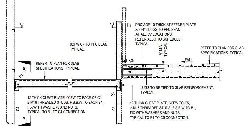
One special thing about the design is the ramp and first floor slabs are concrete but are laid between perimeter steel members. Refer below image.
Supply and Schedule:
This project was undertaken by us during April & May 2020 which was global lockdown period. The project was bit urgent from the client side. After all RFIs, approval submissions, comment implementations, the full pack was submitted by mid of May 2020. We completed it by the desired date even with lesser man power available during lockdown. The project was submitted part by part as requested by the client.
First supply – Pack for Ramp steel and fence steel Second supply – Pack for Stair steel, first floor cast in PFCs and balustrades. Third supply – Pack for columns, lintels and roof members.
A proper coordination between site and detailing team was required as works were undergoing simultaneously. When ramp steel was supplied and they laid concrete, we had to submit the first floor cast in PFCs, cast in plates and balustrades and these must be fabricated before the ramp concrete in done curing. We maintained the schedule properly and no delay happened in the site.
Here is a sample Steel Estimation Report showing, hot rolled, cold rolled and bridging list. If you are accepting the order, then sometimes you will want to make sure that the final drawing does not include extra steel over what you quoted.
If you take a quote from us for detailing and then award the detailing work to us, then our standard procedure is to check the tender drawings against construction drawings to make sure nothing extra is slipped in.
Here is a sample of bridging list we provide with Take off. We provide the length and the quantity for accurate estimation. The model also shows the bridging.
Contour Marking: It is an information written in an NC file that passes information to the NC machine on the layout and the parts that are welded together.
Requested from client
Tek1 do care about every client so we thought of seeking the help of Trimble Connect warehouse and found an plugin suiting the criteria.
Convertor plugin found on Warehouse
How the Convertor Works
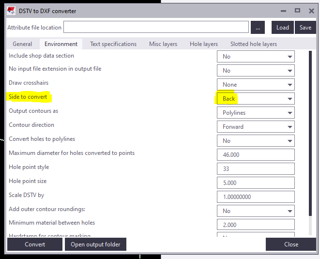
The convertor converts all the NC files to DXF. By default it converts the members in Front View. To obtain the contour marks that are available at the back face few changes had to be done on the convertor setting for efficient changes.
DXF converted output of members with front face weldedDXF converted output of members with back face welded
SETTINGS TO CHANGE FOR EFFICIENT EXPORT
Change “side to convert” under Environment tab as Back in the convertor to create DXF with contour marks at Back view.
Snip from the convertor
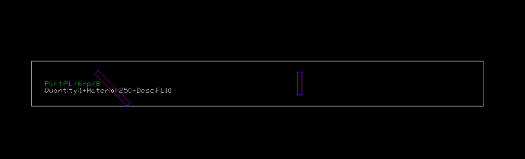
For plates if Back option is chosen you get DXF Files converted like below images. So few advanced settings has to be done.
Snip of Plate profile with Back option chosen
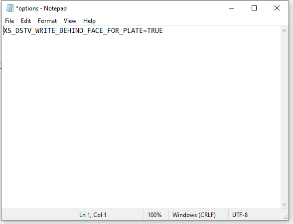
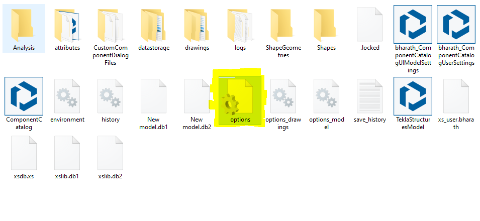
For plates members follow the below steps: 1) Open the model folder 2) Create a new text document 3) Type “XS_DSTV_WRITE_BEHIND_FACE_FOR_PLATE=TRUE“ 4) Save the document as “options.ini“ Refer below snip for Clarity
Snip of NotepadSnip of the File in model folder
Now repeat the conversion the convertor works efficiently providing a quality output.
While working in a project called Bateman Bay, TEK1 came across a situation where PFC members are provided to support glazing. PFCs are laid flat, a 50mm U channel is run along the PFC which supports the glass. The below image is the cross section across the glazing and it elucidate the set up.
Problem 1:
These PFCs are connected to columns by 10mm end plate & 16dia 8.8s bolts. The problem arose here as the bolt head of 8.8s bolt would clash with the glass. Refer below image for clarity.
Hence, TEK1 raised a query as to whether they can cut the glass where ever bolts clash or use CSK bolts. The structural engineer changed the 8.8s bolts to CSK bolts.
Problem 2:
Another problem came as the PFC web is just 4mm whereas the CSK head is 8mm. The bolt head will still clashes with glass.
Then we proposed to weld an 8mm plate under the PFC and CSK drill is to be made together. The proposal is accepted. The below images show that the glazing runs without any hinderance.
TEK1 detected the issue earlier which saved cost in cutting the glass at site. Structural engineer often do not consider these kind of clashes and it is the duty of the modeler to find this out and make this to structural engineer’s knowledge.