Category: Steel Detailing Blog

This page show cases some of the Steel Detailing projectgs completed in Melbourne, Sydney, WA, Brisbane Tek1 has completed

  • Can you spot the Problem#7

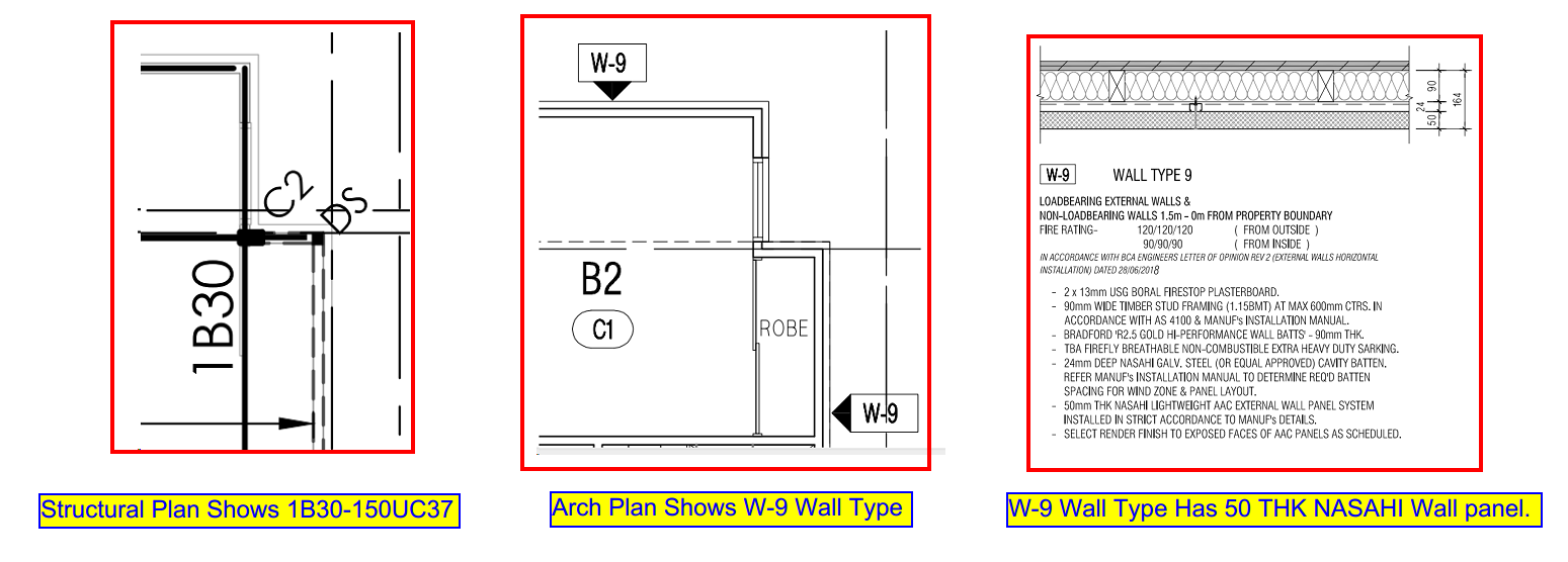
    When we place a beam, we need to consider several factors. The major one is to ensure that the beams do not clash with any of the aesthetical members such as the Cladding, Roof sheets, wall panel etc.
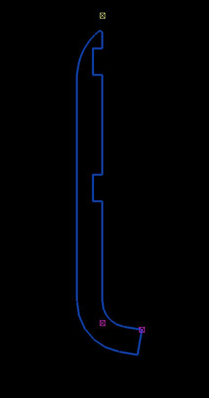
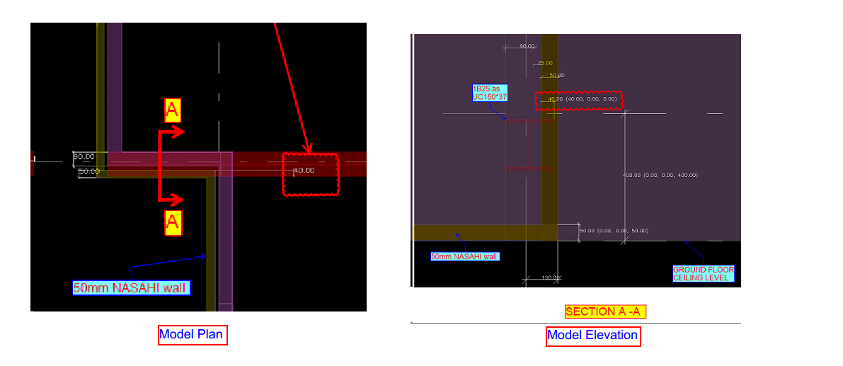
    In this figure.1 The engineer has provided a UC150*37 beam as 1B30 to support the external beam at perimeter and stud wall. If we fix the beam as per the architects specified location it will clash with the external wall finish (NASAHI WALL) by 40mm which is shown in Figure.2. We can not move this beam from its location because the supporting columns are hidden inside the walls for the aesthetic purpose by Architect.

    Engineer provides 150UC37 AS 1B30. Also, Architect prefers 50 thick NASAHI wall finish at the Perimeter.
    Model Snaps Shows the beam Clash with NASAHI wall.

    So we have no choice but to rather change the beam profile, This condition was explained to the Engineer and Architect by our detailer.
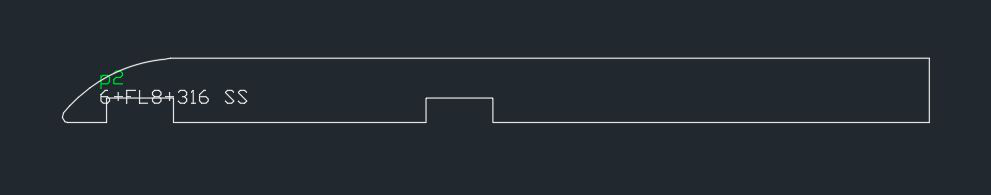
    The requirement was to change beam profile to be concealed and at the same time support the framework, thus was modified to PFC 200*75.

    As we change the beam profile the clash was eliminated

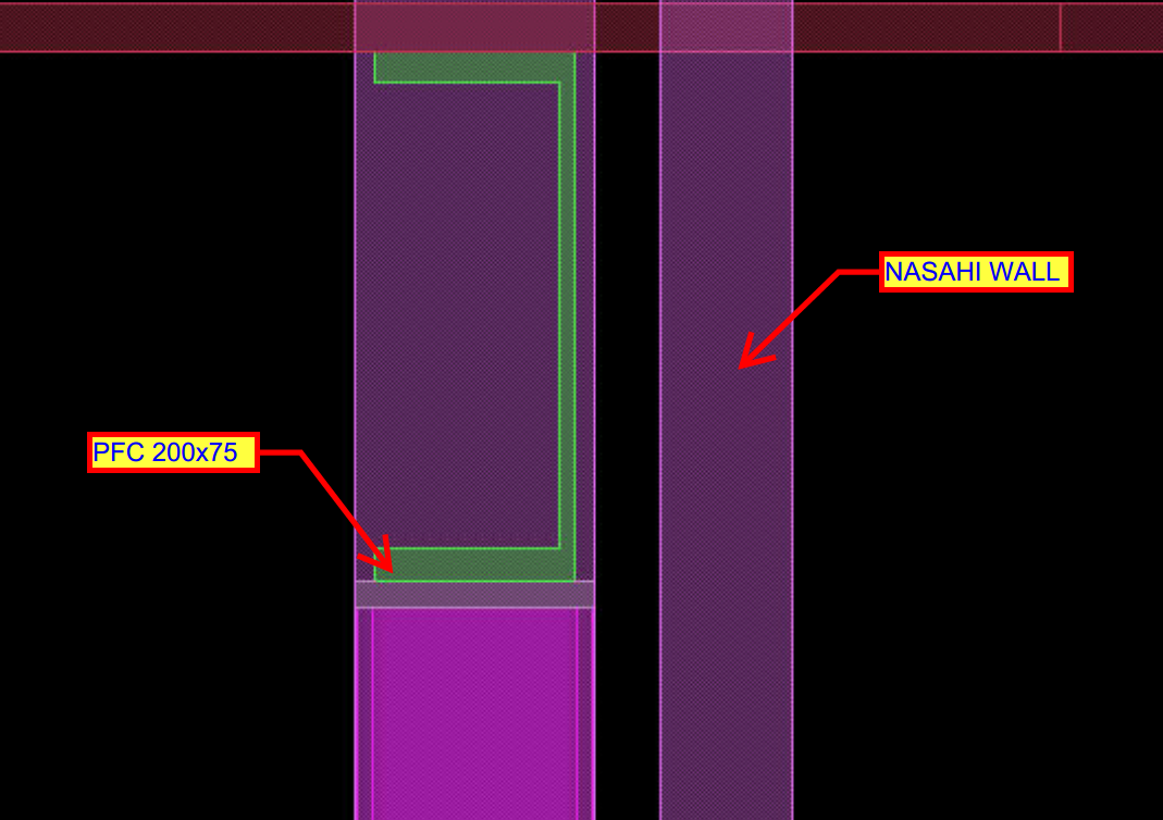
    Always be vigilant about these factors to avoid major mistakes.


  • HAVE YOU TRIED IN AUTO CAD #1: CUSTOM TOOL PALETTES

    Many of the time we use same commands and a set of procedure to work in drafting which consumes time we get used to it over time. For example: to insert a section tag we always need to use insert command and find the block and specify the scale and insert it eventually we need to consider scale of the view port which we are going to present the drawing.

    Instead of doing the same insertion every time we could customize a tool palette so that we could have a tools we use frequently.

    For example we need to label the members with its name in the layer “TAG” and color “GREEN”. We need not edit the property of the text every time. We can create a source file and save it on a common location (so that all the Auto CAD users can use the same file) and have the text in that file. And we could create a custom tab in the tool palette where we could just drag and drop and use it in all other files we work on. It will carry the general properties such as layer, color, line type and line type scale etc.. we could use the same for blocks, dimensions and all geometries as well.

    Notes:

    1. To view tool palette we could use command “TP”
    2. Create a source file in some network drive location with all the blocks so that it is easy for other users to fetch them.
    3. To create a new tool palette right click on the header then customize tool palette.
    4. In the customize window right click on the palettes list and create a new palette. We could do the same by just clicking on new palette option when we right click.
    5. Then we could just drag and drop the entries like blocks into the palette and now we are done with the loading part. We could use the same in any other drawings. It makes the work so easy and also helps by saving a lot of time.
  • Can you spot the problem – #6

    It’s one thing to model something on your computer. It is yet another thing to fabricate what’s drawn in 3d-land. Given the designs that we seen come through, I doubt very much whether the modern day architect has ever stepped foot in a workshop, or has fabricated anything in their lives.

    Consider the below example and see if  you can find any issues that should be blaring at you like a fire alarm.

    Pop quiz: What’s wrong with this?

    Something's not quite right.
    What’s wrong with this?


    What’s wrong here?


    Answer:

    • I think you might struggle to build it. I don’t think you can curve a PFC125 x 75 with a radius of 125 mm.
    • Can you think of an alternate solution?
    Ok, here's how we can fix the problem.
    Ok, here’s how we can fix the problem.


    Written by Gopal D.

  • .dwg based Take off with custom Plug ins

    Tek1 has developed .dwg based plugins which talk to Tekla to carry out take-off efficiently

    Take off is completed in .dwg based Cad systems very similar to modeling in Tekla. For BIM model the model is converted to Tekla

    Reports can be taken either from .dwg system or Tekla. Right now reports are being taken out of Tekla. Our next effort is to develop a plugin which will convert the .dwg model into an IFC model.

    If anyone is able to help us in this developing the plug int convert .dwg based model to an IFC model we will be very interested.

    Here is a sample file.

    Queens Cliff Estimation Model
    Tak off model
  • How to do material take offs cheaply

    Take offs needn’t be expensive. If you want accurate reports and a good IFC model you can spin around, you can get it done easily, with some custom software. Now you can get your take-offs done cheaply, and with the quality being just as good.

    Check out this video, which explains it all:


    How we do Material Take-offs – Tek1 from Tek1 on Vimeo.

  • DXF problems when using Polybeam “L” shape plates

    The DXF format is a CAD data file format developed by Autodesk to allow data interoperability between AutoCAD and other CAD programs.

    Issue: One issue we faced when using the polybeam comments feature in Tekla is that if we used the feature to add comments on a DXF file imported into Tekla, then the output drawing will render the proper shape.

    See the image below for the plate shape.

    Try a contour plate.
    This won’t work. This is best modelled as a countour plate.


    See the below for the DXF output shape. The bending portion will not appear properly.

    DXF – this is output. It won’t work with polybeams.


    Solution:

    Don’t use poly beam comments in Tekla model to the “L” shape plates.

    Instead, use the Contour plate comment to make the “L” shape plate in model.


  • IntelliCad based Tools to support Material Take-off

    You don’t need to spend $30,000 p/a on Tekla licenses. You can estimate steel based on IntelliCad based software. Here’s some software I wrote to make this happen:


    How to Model Beams on Intellicad based software from Tek1 on Vimeo.


    Demo: Create beam and Create Beam Lines from Tek1 on Vimeo.

  • Liverpool Catholic Club | Sydney Project

    Liverpool Catholic Club | Sydney Project

    Sydeny Fabricators trust in Tek1

    This is the first project we have detailed for Gonzo Engineering many years back.

    Gonzo is still one of our top clients.

    Many sydney fabricators have put their trust to use tek1 for their major projects

    View this article to see the Emu In the sky, detailed by Tek1 for a major Sydney fabricator

    Emu in the Sky | Sydney

    Tek1 has completed this rather complicated project with support from a brilliant detailing team. The project was complex demanded a very high level of detailing knowledge. We have put our best guys on this job. They have done wonderfully well in completing this project without a hitch.  The builder in this instance was Kane Constructions. The fabricator Gonzo engineering.

    You may visit our Services page for more information for the type of work we doe

  • Working with Site Measurements

    WORKING WITH EXISTING STEEL

    There are big risks involved with working with existing Steel
    Things to note.
    RL /Height Measurements.
    You probably will have to give careful consideration as to what was site measured and what references were used.
    Most common errors
    1. Heights measured from Floor to underside of beams. But the floor is sloping
    2. Beam Cols side or centerline used as a reference. But Size and Orientation of beam not confirmes. Both Size and Orientation should be confirmed
    3. The measurement from a wall given. But the wall does not run parallel. By the time the measurement comes to the level we need, measurements are out.
    4. References are taken from something which we cannot reproduce accurately on our drawings.
    5. Site measurements do not add up to the overall. (This is common.) You have to ask which references we should be using and use the same references to set out the members.
    6. Measurement errors could create erection problems. Analyze potential problems and counter for that.
    7. Be extremely careful when the site measure is not from the total station. Most of the errors we see are from site measures taken with handheld lasers and measuring tape.
    Points we have to take care of.
    1. Understand site measure clearly.
    2. Understand Rls and setout which can affect our steel, for example beam, and col size, orientation, Sloping floor. Non-parallel beams.
    3. ASK FOR PICTURES. PICTURES WILL TELL A LOT. ASK FOR VIDEOS TODAY CREATING VIDEO ON THE MOBILE PHONE IS EXTREMELY EASY SO ASK FOR IT