Here is video on how to create unequally spaced gridlines in Advanced steel
Category: Steel Detailing Blog
This page show cases some of the Steel Detailing projectgs completed in Melbourne, Sydney, WA, Brisbane Tek1 has completed
-
How to create a 4 line unidirection grid in Advance Steel
This video explains how to create a 4 line unidirectional grid in Advance Steel
Please watch the video and practice it until you understand it. Any questions pls talk to me.
-
advancesteel-Switch on tool palettes
I struggled a bit on finding the tool palette and switch it on and off. But once you know it is a no brainer. Here is a video on how to switch on and off the tool palette in advance steel
-
Can it be built? Holes near the flange
Erection Feasibility must always be considered when creating shop drawings. Consider the diagram below:
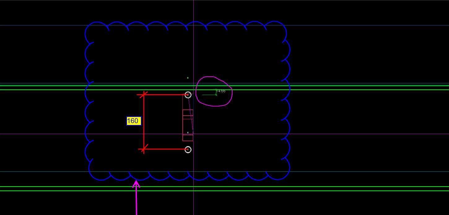
Can you spot the problem with this drawing? This is meant to be a side-on view of a beam. The green lines represent the flanges of the beam. The white circles represent holes to be drilled. What is the problem here? Consider the distances highlighted. Pop-quiz: What is wrong with the above drawing?
(Scroll down for the answers)
(Scroll down for the answers)
(Scroll down for the answers)
The Answer:
Drilling a hole so close to the flange is not easy, neither will it be easy to pass a rod through when it is so close to the flange. You only have 14 mm till the edge of the flange. What if you used the standard pitch of 160 by route – but you’ve also got to consider erection feasibility!
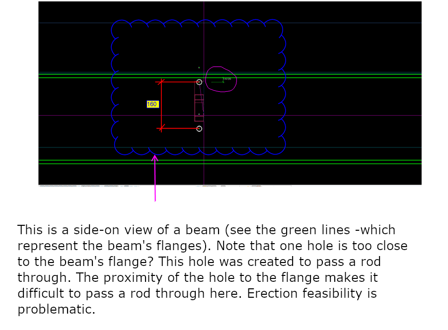
Placing a hole so close to the flange will not work. -
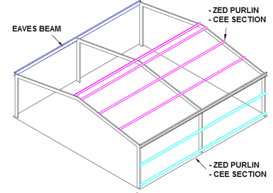
Which way should the purlin be oriented? (Detailing Tips: No. 5)
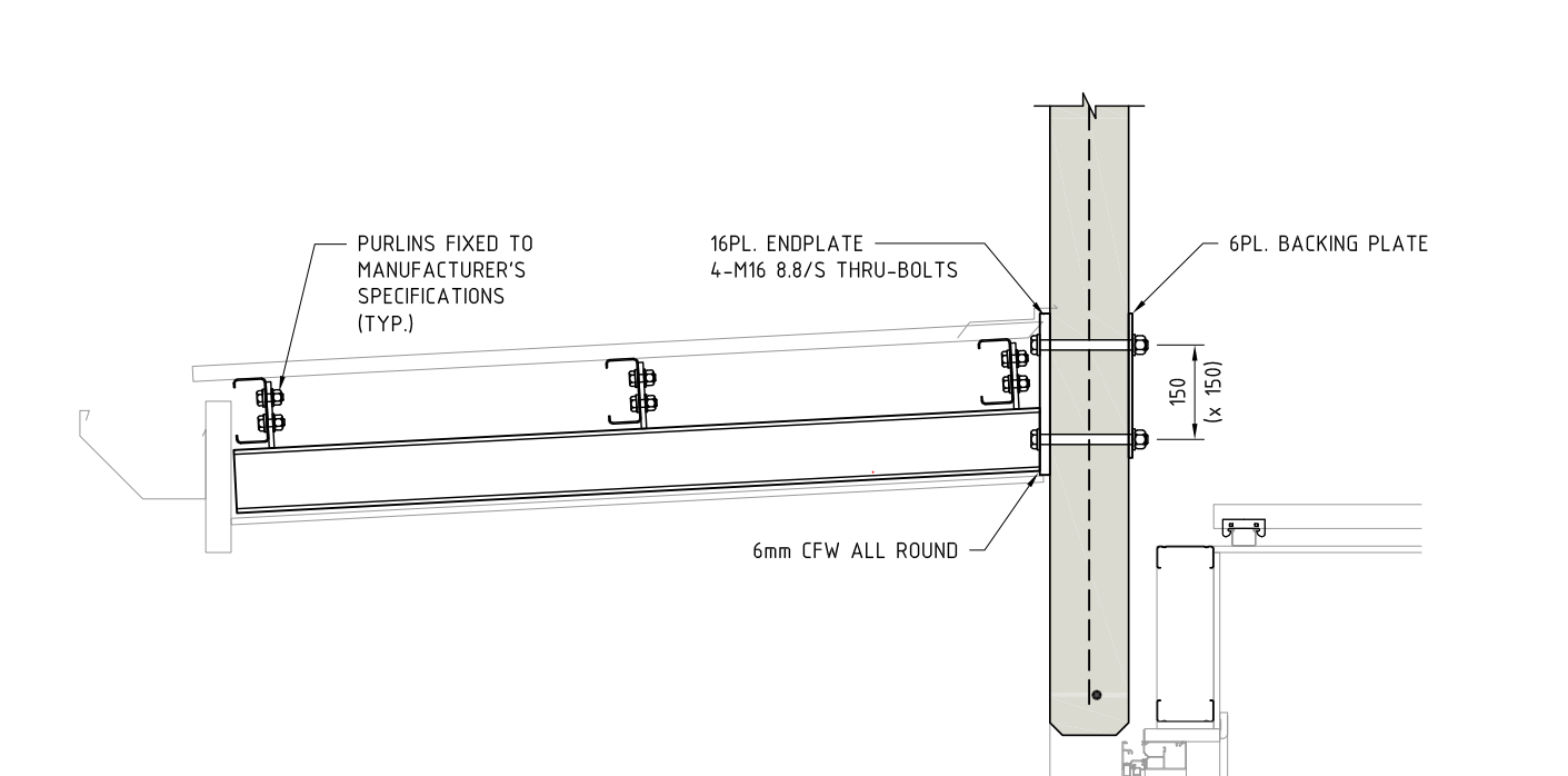
Consider the above drawing (Section View)? Have the purlins been placed correctly? Have you ever considered a purlin’s orientation while detailing?
Pop-Quiz:
In the pic above, the structural engineer shows the purlin direction along the roof slope. Is this the correct way of orienting the purlin? i.e. Has the engineer made a mistake, and if so, why? (Answers below)
(Keep scrolling down…)
(Keep scrolling down…)
(Keep scrolling down…)
(Keep scrolling down…)
Answer:
Definitely, this is an error on the structural drawing. Generally, detaliers have to consider a purlin’s orientation before placing it. Why? When the load applies on roof sheets , a twisting moment will occurs on the purlins. If we place the purlin direction along the roof slope then it will cause instability. So, the purlin direction should be always kept against the roof slope (as indicated in pic), even if the design indicates along the roof slope. Keep that in mind when you are detailing your next job. It’s a subtle but very important tip.
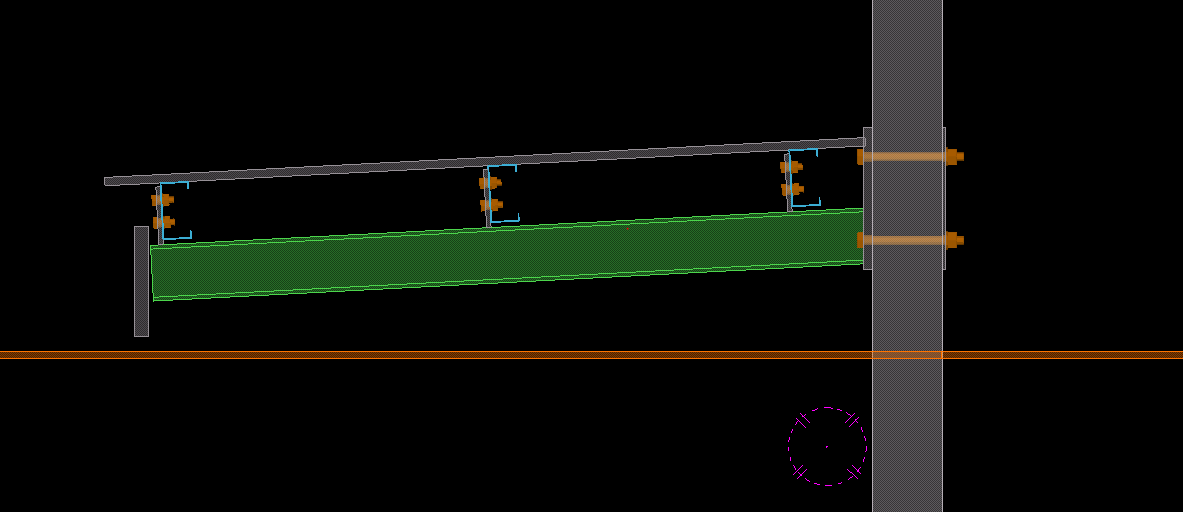
Notice how the purlins are oriented against the roof sheet? -
How to Export a Tekla Drawing to PDF (Using the PDF Forge’s PDF creator) (Detailing Tips: No. 4)
To export Tekla drawings to PDF, various converter applications are available in the market. One of them is PDF creator by PDF forge. This is a free product and can be downloaded and installed directly to your system.
The following is the step by step procedure for pdf creator which can be used to set up your export files directly to a specific location.
- Open the application PDF creator (should be already installed onto the system).
- Select Options:
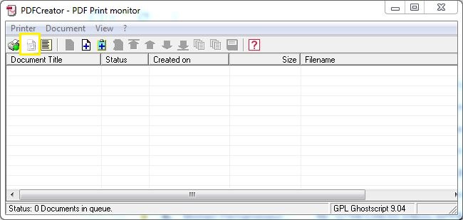
This is the UI. Selection Options (see what’s highlighted) - Now select and use Auto-save.
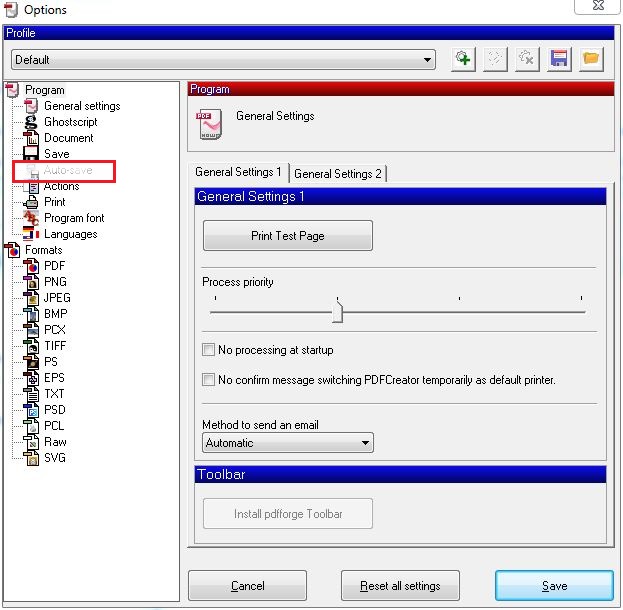
Select Autosave - Provide file name to <Title>. Provide the directory location where you require the pdf’s:
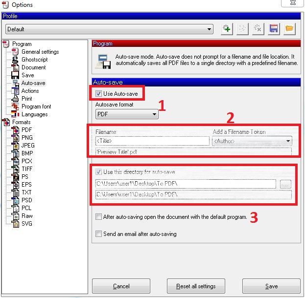
- Save and close the Dialog box.
- Now you can print to pdf using the PDF creator application.
You can download the free product from the following link: http://download.pdfforge.org/download/pdfcreator/PDFCreator-stable
(But be careful what you download: you do not want to get an internet transmitted disease by downloading from an irreputable source. Practice safe downloading: use anti-virus protection! Don’t hold me to account for that link).
-
BIM review from Strumis (Detailing Tips: No. 3)
BIM review from Strumis
BIM review is a desktlop software application by Strumis. It is similar to to Trimble’s Tekla BIMsight, having features such as: (i) clash checking capabilities, (ii) camera path viewpoints, and multiple format are supported including ifc xml step etc.
However we have to work to our clients requirements and at many instances they may not have access to Tekla BIMsight which is our standard protocol for model review. That can directly affect us.
Thus an simple installation of the BIM review application and Tekla plugin for extraction of BIM review compatible files may be necessary.
The BIM review application is a free product and can be downloaded and installed directly with an active internet connection.
Installation Procedures:
- Install the application STRUMIS/BIMREVIEW to Tekla Structures Plugin from tekla warehouse. Download and install the version of tekla you are using.
- Once installation is completed you can open your tekla project and go to Component catalogue (ctrl+F).
- Search for BIMReview and the following items will be shown.
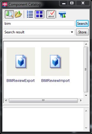
Search for Bim Review in the Component Catalogue. - Select BIMReview Export plugin and following window will be shown.
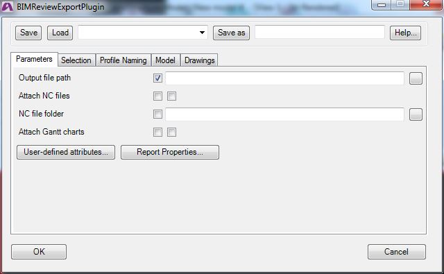
This will be the window shown when the Bim Review plugin is selected. - Provide the output path and turn on/off the attach NC files and File location.
- Other tabs leave as it. I am still in progress of identifying each purpose.
- Select the objects you require to be added and click OK.
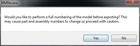
Select the objects you require and you’re off to the races! - Preferably you can do numbering as per your standard procedure, and provide No to any numbering changes.
- Your Export will start now.
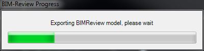
An export progress bar will show. - Export completed notification with warning if any will be shown.
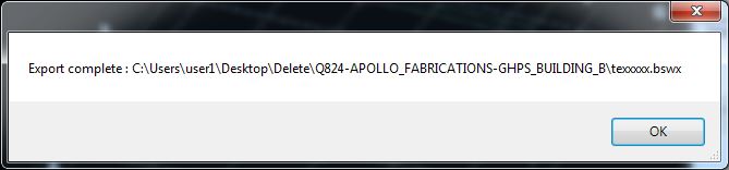
- Your .DSWX file will be created at your requested location.
- You can now view the exported file on BIM review application which can be downloaded at the following link.
http://www.bim-review.com/essentials.php
I hope this helps!
-
Is it supported? (Detailing Tips: No. 2)
We continue our “Lessons learned” series. Can you spot the snake in the grass, in the following problem?
There are a million gotchas when detailing, which can trip up even the most experienced detailer. Here’s an issue that snagged us. Hopefully you can learn from our cock-up.
Showing building supports. Generally, roof sheets are provided by the roof sheet erectors. But they want supports for the roof sheets from steel which given by steel detailers. Structural engineers will not give details for roof supports all the time. Sometimes they will miss it, or they will leave it to detailers. If that occurs, detailers must come with their own design (but, must get approval by struct engineers).
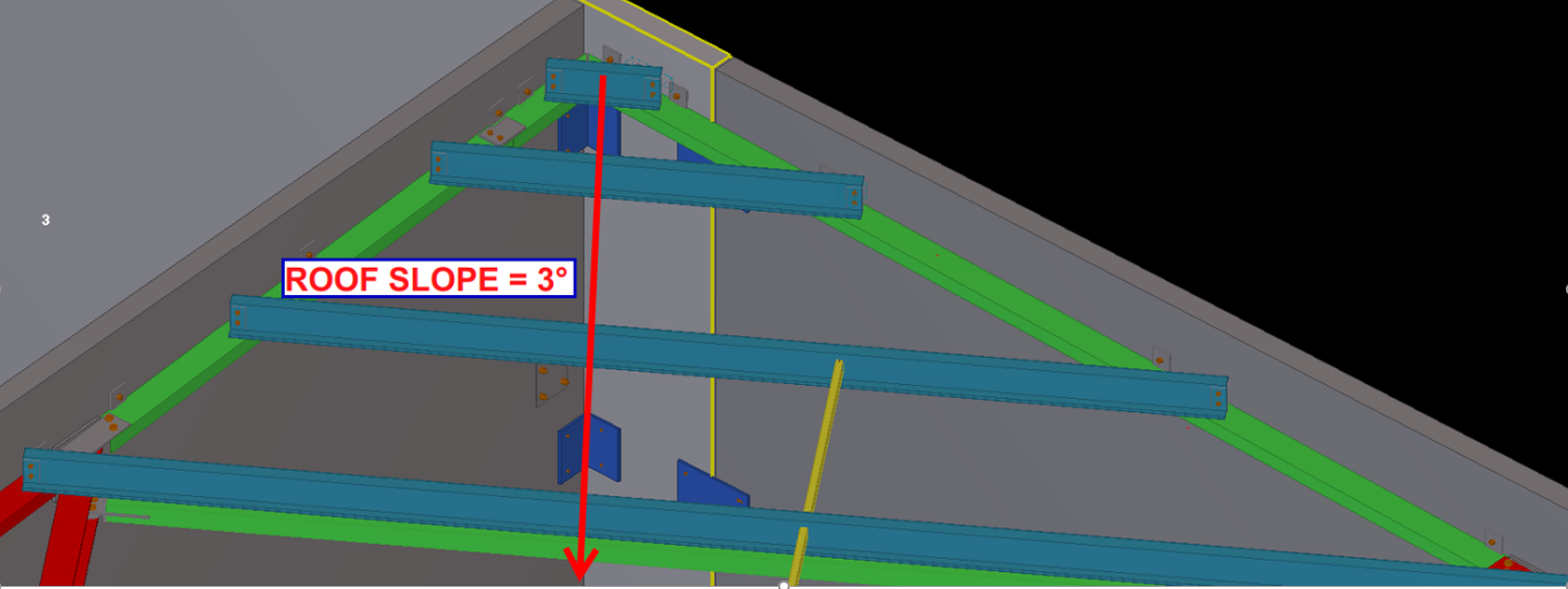
Showing the slope of the roof. There are purlins in this picture to support the roof sheets. Detailers did their job as per structural documents. So that detailer’s work is finished. Pop quiz: the detailer’s work is finished, right?
If you think like this, then you are wrong. Have a deep look into that: there are no supports for roof sheets around the perimeter of the roof.
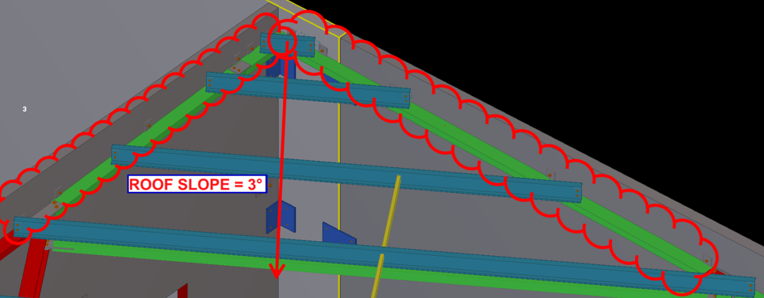
The supports are missing, around the perimeter. So at this situation detailers must check whether there is support for roof sheets at every ends. If there is any conflict found, you must need to provide steel for roof perimeter supports. Refer below images.
Here are the steels that are provided by our detailers. This can prevent site issues. Rectification on site is extremely costly, and worse, it’s extremely time consuming. You can avoid nasty delays by some carefully investigating the drawings, and avoiding dangerous pitfalls early on.
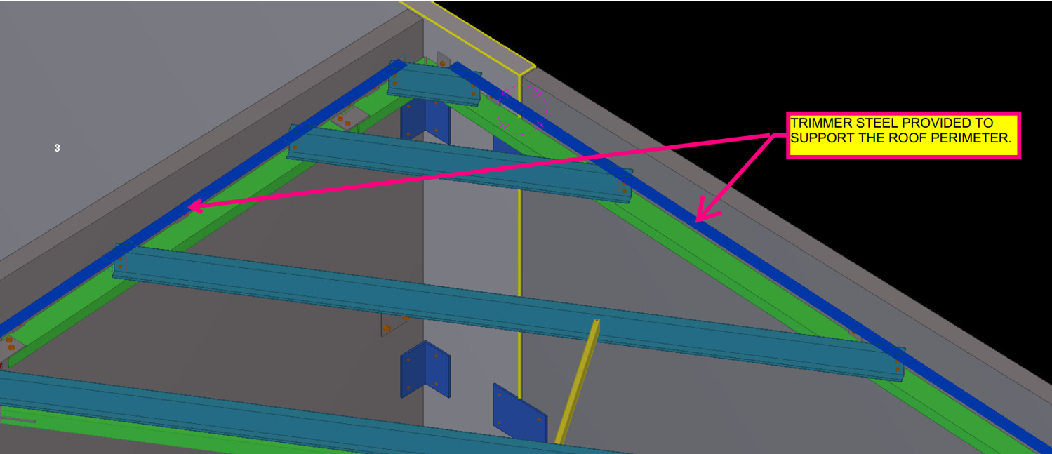
The supports are now drawn. Site issues are avoided. -
Does it Fit? An Example of an Erection feasibility check against particular steel profiles (Detailing Tips: No. 1)
As a detailer, we should constantly inspect and second guess the drawings and the details given to us by engineers and architects (well, mostly architects, because as a general rule, engineers are competent).
The Pop-Quiz
If you wish to engage in a pop-quiz: see the drawing attached here: Spigot Connection. What problems can you see arising if you follow the details put forward. The answers are contained below. Scroll down If you wish to see them.
Scroll down for the answers.
Scroll down for the answers.
Scroll down for the answers.
Scroll down for the answers.
Scroll down for the answers.
….Ok here are the answers:
See the link here: Marked Up Pdf Showing Spigot Connection. The structural drawing details the spigot connection required.
Actually, the Steel post profile size is SHS 89*89*6 and the Steel stub profile size is SHS 75*75*6.
So we will get an overall 2mm allowance between Steel stub and post.
In this case we must consider the nature of the steel profile types.
In the market we are have two different types of profiles, One is Seam SHS and another one is Seamless SHS.
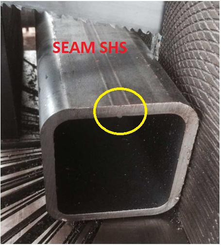
See how there’s a notch here? Ok now we need a bit more clearance. This is because of the process by which this member was created. It starts of like a flat piece of metal, and is basically folded into a square. So the notch will be on the inside, where it is difficult to smooth off. 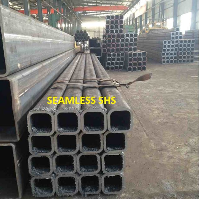
Notice there is no notch inside? The clearance can be a little smaller in this case. If we use Seamless SHS profile, then we can erect the members, Otherwise if the SHS are of the seam profile type then we can’t erect the member – there is not enough of a clearance.
Before carrying on the structural details we must discuss with Client/Fabricators and confirm which type of SHS they are going to use.
If they have Seam SHS only, then we must reduce the stub profile and make more clearance for the easy erection.
Written By Arokiaraj and his team; Our mistake in this regard was helpfully pointed out by Brett Kennard of Apollo Fabrication. Brilliant.