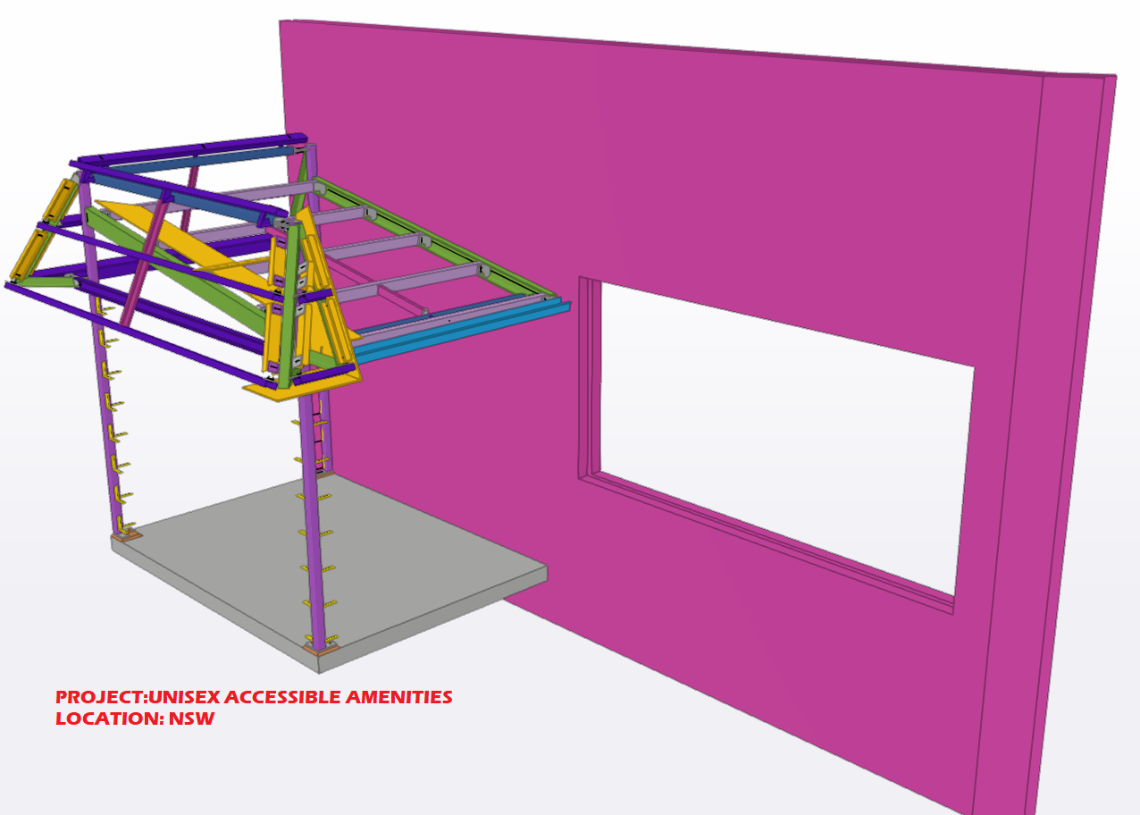
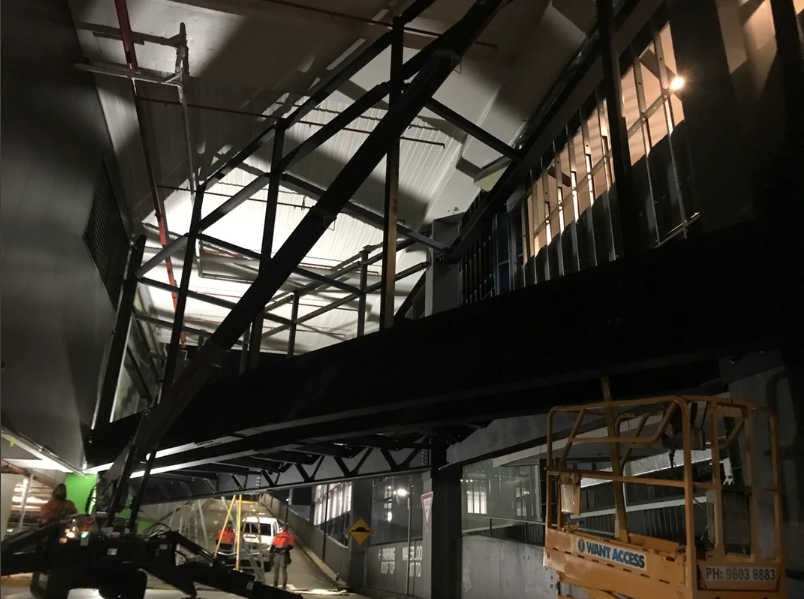
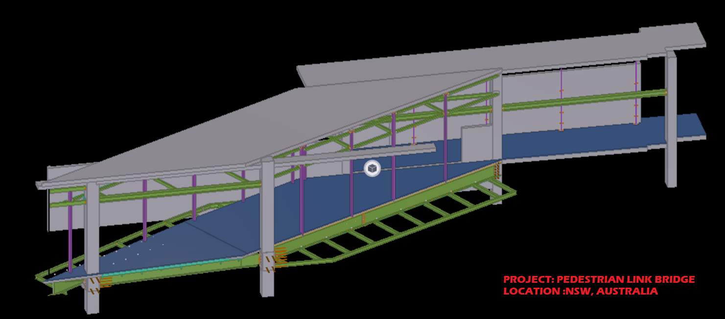
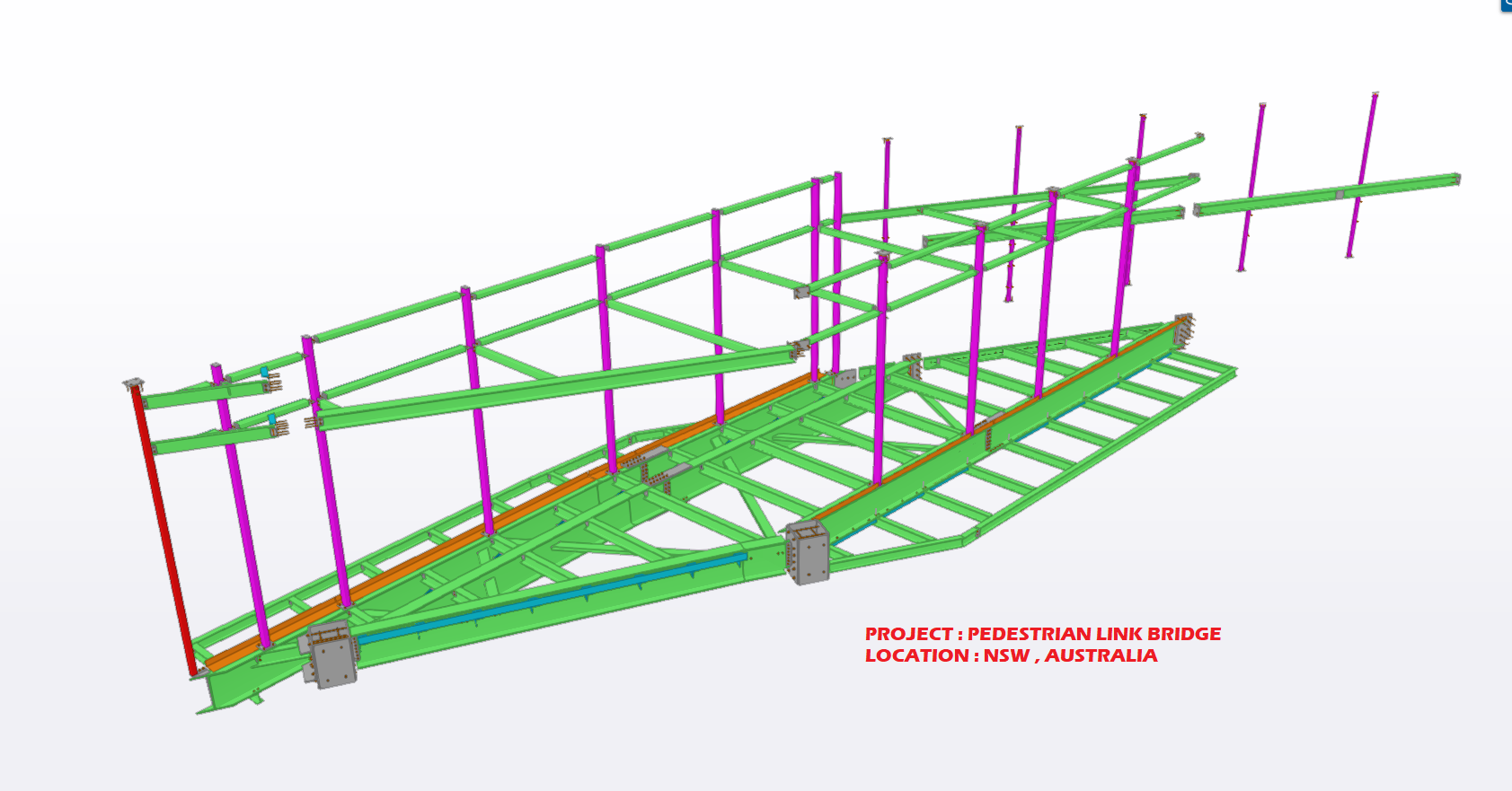
TEK1 done a detailing work for the link bridge.The complication of this project is site measure. We have to co ordinate with the existing building site measure to finish this work.Most of the structural members are connected to the existing concrete.We have coordinated with site surveyor & got the dimension we want to connect the steel.
TEK1 completed this job without any mess.We have provided a good info to fabricator as well as erector to finish this project smoothly.
Precast erection procedure having the set of sequences. When the panel is installed on the slab, props are fixed to stable the panel, then panel was unhooked from crane then the temporary stich plate or stich angles are connected to the next panel through cast in ferrule, which is casted on the precast panel.
The temporary connection is additional support for the precast panel for until grouting the grout tube & slab were connected to the particular panel. The panels are easily leveled up with respect to the connected panel. Minimize the no of brace connections. Easy to maintain the panel gap.
Based on the position of panels & face of the connection it is classified as below,
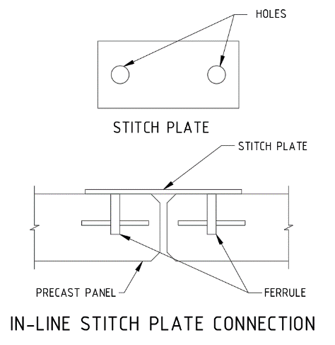
1. In-line stich plate:
When the panel are next to each other the temporary connections are made by the straight stich plate with ferrule as mentioned below picture.
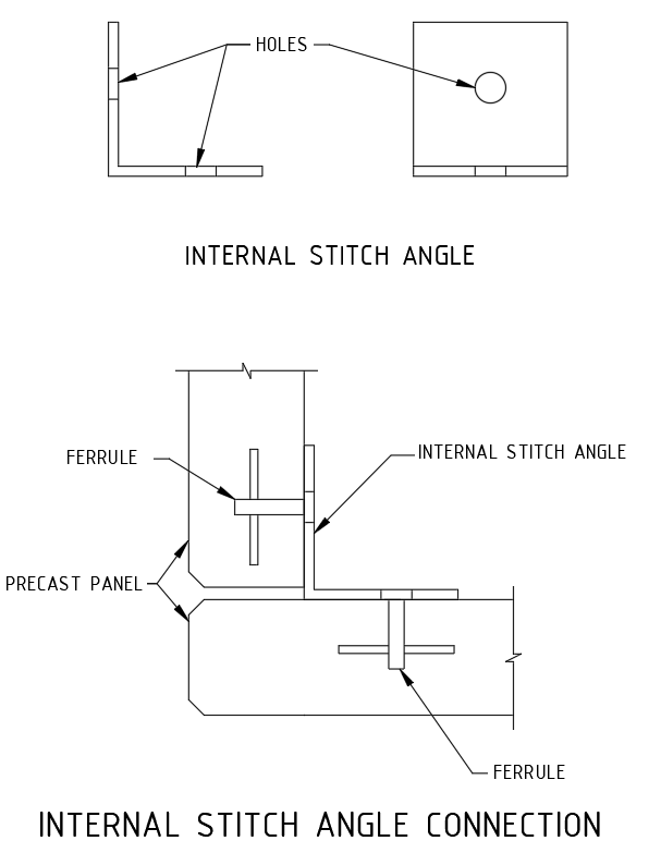
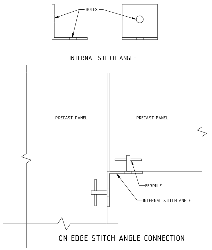
2.Internal Stich angle:
When the panel is perpendicular each other and inside corner is access to perform the connection, the internal angle stich angle is being used.
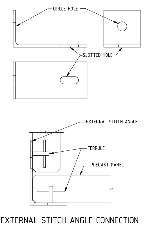
3. External stich angle:
When the panel is perpendicular each other and outside corner alone is access to perform the connection, the external angle stich angle is being used.
4.On edge stich angle connection.
Some cases, same level panels one is erected on top of slab and another one is located on ceiling level is supported by on-edge ferrule mentioned as below picture.
Precast panels are ready made concrete element, which is the part of the building as structural as well as façade panels, which required the surface finish as per the customer or Architect requirements. Various type of finishes are used on the both side of panel and edges according to where the panels are positioned on the building.
Due to the process of precast manufacturing, the finishes are made by replication of table on the one side, and the other side our traditional or conventional methods are preformed after pouring the concrete. As per concern of precast finishes, its classified as
2. Table Finishes.
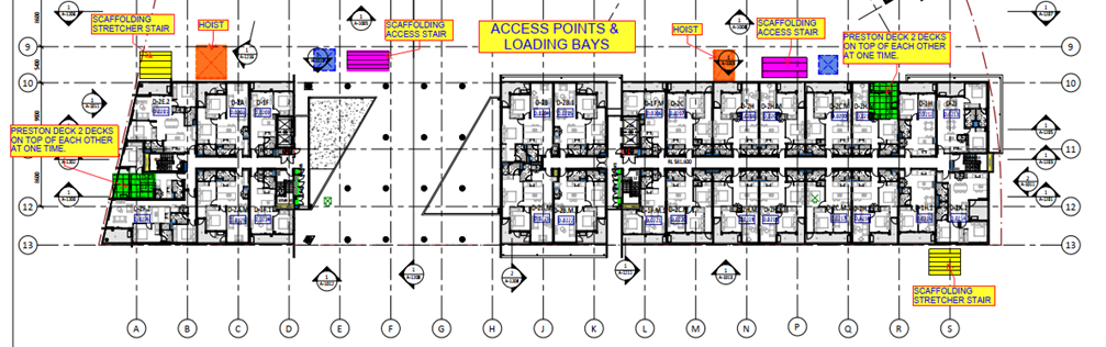
Every multi story buildings typically need the loading bay or hoist for each and every level during construction. A loading bay or loading dock is an area of a building where goods are loaded and unloaded to it from vehicle or site. On hoist or loading area of façade walls is being unbuilt up to end of construction. Final stage of construction only it needs to be built. Refer below picture for different types of loading bays are highlighted.
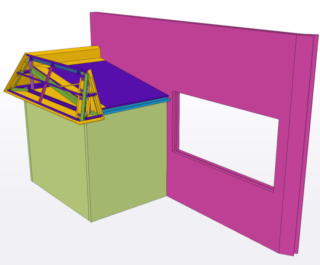
If the rest of the building is constructed by the precast, the hoist area also needs to be covered or fixed by precast panel. This type of covering panels are named post fix panel. Which means the panel will fix on the existing structure after completion of required task.
These post fix panels have different type of erection procedure, connection details compared to the all-other precast panels.
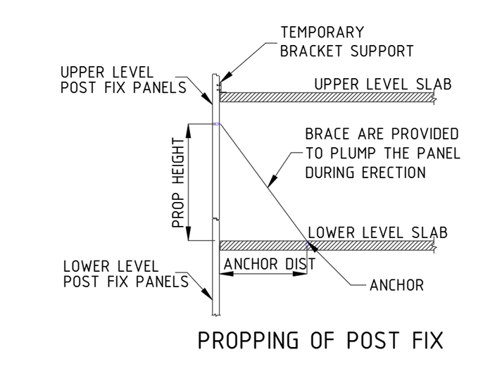
Propping Method for Post Fix Precast:
The temporary bracket connection between panel and to the slab need to be done at the top of the panel. The rest of the panel hanging below slab where braces are connected to plumb the panel as well as support. That the brace is anchored below level slab. The bottom of post fix panels is connected with dowel & grout tube arrangement to the below level precast panel. Refer the propping snap.
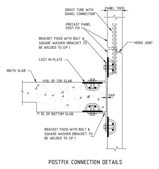
Permanent Connection of post fix panel:
The grout tube with dowel connection between the panels are only resist the horizontal movement, the additional permanent connection is made between panel and the slab through cast in plate and weld on site at both top and bottom the slab. The structural connections details are need structural engineer approvals. Refer below picture for typical connection details.
Demoulding of precast member without damage to either the components like lifter or mould is critical to successful replication process for the particular complicated design. During mould design, the designers concentrate to make minimum draft (nearly 10 ) on mould to wherever the possible to minimize demoulding force and resultant stress on lifters and prevent on weaker part of the precast member.
For Example,
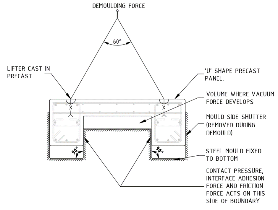
CONTRIBUTORS DURING DEMOULDING WITHOUT SLOPE
The above picture shows influencing factors for demoulding force. In this case the resultant DEMOULDING forces like vacuum & friction (Area of contact, Coefficient of friction & Normal contact Pressure) along with self-weight of precast will increase demoulding force. If the demoulding force exceed the lifter capacity limit leads to fail the lifters. So, we can’t able to lift this precast member. To eliminate this type of failure. We need to provide slope where contact pressure or interface adhesion develop.
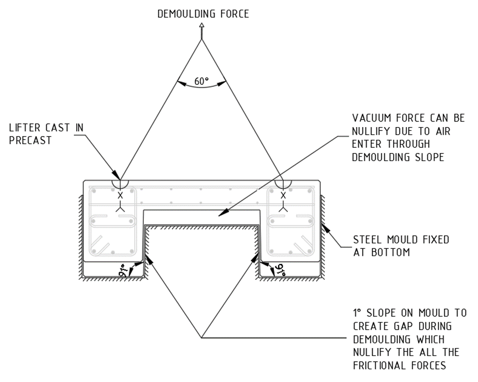
CONTRIBUTORS DURING DEMOULDING WITH SLOPE
The above picture shows the effect of demoulding slope. Where the 10 slope didn’t affect too much the original shape of precast, but considerably minimize the demoulding force. The slope reduces the frictional force & provide passage to air enter where vacuum force develops.
CONCRETE:
(AS 1379 Specification and supply of concrete) A mixture of Cement, aggregates and water with or without the addition of chemical admixtures or other materials.
Cement: (AS 3972 Portland or blended cement) A hydraulic binder composed of Portland or blended cement used alone or in combination with one or more supplementary cementitious materials.
Concrete is defined as follows,
Concrete in the state between completion of mixing and initial set as defined in AS 1012.18 Methods of determining setting time of fresh concrete, mortar and grout by penetration resistance.
Concrete after initial set, as represented by test specimens that have been subjected to a specified process and duration of curing.
Concrete that is specified primarily by a standard compressive strength grade up to 50 MPa and otherwise in accordance with Clause 1.5.3.
Concrete that is specified to have certain properties or characteristics different from, or additional to, those of normal-class concrete and otherwise in accordance with Clause 1.5.4.
SPECIFICATION OF CONCRETE:
Concrete shall be specified,
(a) as either
(1) Normal-class(N), or
(2) Special-class(S), or
(b) By strength grade or other readily verifiable parameter by which compliance with the specification can be assessed.
NOTE: Standard strength grades should be specified wherever possible.
Normal-class concrete shall be specified only by the parameters given in Clause 1.5.3.2(Basic parameter), and shall have the following attributes:
NOTE: This maximum value of 1000 × 10−6 is consistent with the use for design purposes of a median basic shrinkage strain value of 850 × 10−6.
Basic parameters of normal-class concrete:
The following basic parameters shall be specified by the customer:
NOTES:
NOTE: If unspecified, it will be assumed that project assessment is not required.
(2) SPECIAL- CLASS CONCRETE:
Concrete other than normal-class concrete shall be specified by the customer as specialclass and, if applicable, by strength-grade. The parameters and attributes that should be specified for special-class concrete should be as set out listed below with reference to Appendix B and Table B1 on AS1379.
Special-class concrete commonly has the same basic parameters as normal-class concrete with some additions and(or) exceptions. Parameters or attributes that are different from, or additional to, those of normal-class concrete should be included in specification below. If the requirements of specification for any concrete are inconsistent with those for normal-class concrete then the requirements of specification take precedence for that concrete.
Where any parameter other than strength grade requires the specification of a special-class concrete, or the proportions of the mix are specified, the concrete should be identified by an appropriate code agreed to between the supplier and customer that identifies that particular mix.
Basic parameter for specification of special-class concrete:
S, for compressive strength grades;
SF, for flexural strength grades; or
ST, for indirect-tensile strength grades.
Where concrete is special-class and any property other than strength grade is Specified as the principal criterion, or the proportions of the mix are specified, it is designated by an appropriate alphanumeric code, agreed between the supplier and the customer, to indicate the criterion.
NOTE: A summary list of several such parameters, some or all of which may be specified for the production of special-class concrete for a project, is given in Appendix B on AS 1379.
Here is a quiz that Bharath has written. Very relevant.
Engineers Architects are trying to wriggle out of their responsibilities by stamping “VIEWED” or “No COMMENT”. They do not want to stamp approved for fear of any error in the document could come back and bite.
Insurance companies on the other hand are trying to minimize their risk when they provide insurance to detailers by explicitly stating, they will not cover the detailer unless the drawings are stamped for approval by the engineer and architect, and anyone else.
To cut the discussion short, if the detailer issues without approval then the detailer will put everyone at risk because there will be no insurance cover. Detailers are the smallest in the chain. Try to litigate against the detailer is unlikely to get any good result. They could simply windup.
Now here is the quiz
https://docs.google.com/forms/d/e/1FAIpQLScspZzCdNBlwVb4FJcB3rUebNuaZHBk28goPcUBHGFXz-aQiA/viewform
We comply to Australian Governments privacy policy as in the URL given below
https://www.oaic.gov.au/about-us/our-corporate-information/key-documents/privacy-policy/