Tag: Bubble deck

  • Bubble deck Slab

    What is Bubble deck Slab?

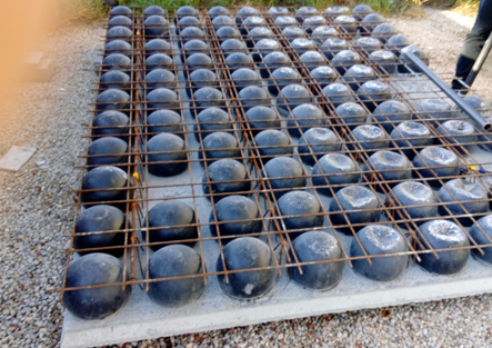
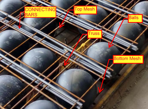
            The slab that comprises of plastic void balls in middle which are sandwiched between top and bottom mesh to reduce the dead weight act on the slab

            It is a biaxial hollow core slab where the concrete which is not performing any structural function are eliminated lead to reduction in 30% to 50% of its slab weight

    Principle:

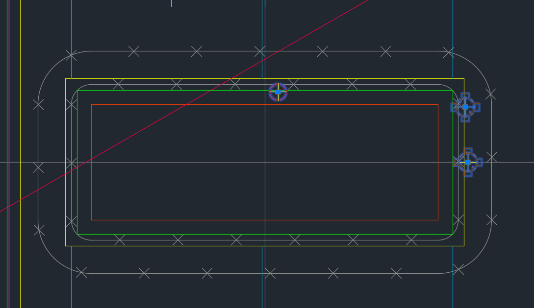
         The Hollow plastic balls clamped with the top and bottom reinforcement are placed in the thin concrete of 60mm with max length and width of 10m x 3m to form a precast setup will be done in factory. After that the setup will be installed on site with connecting rods and by pouring concrete

         The 35% saving in concrete composition was achieved by the ratio of Plastic ball diameter to the thickness of the slab depth

      The reduction in slab weight leads to achieve the Load bearing capacity at a smaller slab thickness result in saving 40 to 50% of material consumption per Floor level.

    Materials for Bubble deck slab:

    Concrete

    • Standard with max aggregate size of 20mm
    • No plasticizers needed for concrete mix
    • Grade of concrete must be above M30

    Reinforcement

    • Grade Fe-600 strength or high
    • Top mesh and Bottom Mesh reo of N12 bars max
    • Truss arrangements for vertical support of balls. Truss height depends on slab depth

    Plastic Balls

    • Hollow sphere Plastic balls made of Polyethylene
    • Diameter of balls are depends on the Slab Depth. Ball sizes are 180mm, 225mm, 270mm, 315mm and 360mm.

    Applications of Bubble deck Slab

      Superior Architectural Design

    • Free choice of shape
    • Large corbels
    • Large spans and cantilever
    • No beam and fewer column results in flexibility
    • Interior design can be easily being altered.

    Advantages:

    Structural

    • Reduce the foundation size since 50% of the dead weight is already reduced by the slab.
    • Increased Strength due to biaxial Loading.
    • Longer spans are supported since no bean is required.
    • Column count can be reduced.
    • Excavation required less work.
    • Conduits and openings for service ducts can be easily incorporate in factory.

    Construction

    • Less equipment is required due to light in weight.
    • Less work on Site construction.
    • Shuttering work and its Dismantling is not required since the 60mm concrete biscuit will act as shutter.
    • Construction hours and time taken is very less compare to conventional Slab

    Engineering

    • High resistance against explosion due to biaxial flat slab system.
    • High Resistance to earthquake due to slab acts as elastic vertical structure.
    • User friendly to Post tensioning if running through slab.

    Environment

    • CO2 emission due to concrete manufacturing quantity are reduced
    • Less material consumption
    • Less energy consumption
    • Less wood as no horizontal scaffolding

    Economy

    • Sustainable for easy installation
    • Made to measure and saving material
    • Fast Implementation and construction
    • Reduction in Transportation Loading cost.
    • No shuttering  and its cost needed

    Disadvantage

    • Deflection will less higher than the Conventional Slab
    • Load carrying Capacity is lesser than the Conventional slab
    • Skilled labour required
    • Shear Load design consideration and its  factor near the column area to slab care is required

  • How does Tek1 do Bubble Deck? Our Shop Drawing Processes

    Sample Drawings

    The best way is via demonstration. Please see some of the video demos we have put together. It is not by accident that our drawings come to you quickly. There are 10 distinct stages. We will upload the rest of the stages as we get and when we get an opportunity.

    The full list is here:

    Many commands do not have any video documentation attached. Some of the ones we have are documented below:

    We have updated our Insert Panel Lifters command:

    Dimension Tooling

    1 – Layout Commands

    enter help info here

    2 – Shop Drawing preparation

    3 – Bill of Materials

    4 – Dimension Panels

    enter help info here

    Insert Blocks

    enter help info here.

    Utilities

  • Jigging with SHIFT, CTRL and Mouse Wheel Functionality (AutoCAD .net API)

    If writing software then make it easy for your users.
    User Input is critical. You gotta make the user experience amazing.

    Any AutoCAD programmer knows that things which an algorithm may take a million years and infinite computational power to do can sometimes be easily done by a human being instantly. In the same way it is sometimes much easier to give a human being the ability to choose: then you can get an optimum result without complex algorithms.

    This post is a code snipped of how you can utilise the CTRL + SHIFT + Mouse Wheel (up/down) mechanisms in order to produce different desired results when operating a custom jig.

    Here is the code:


    So when the appropriate user input happens, then the jig can respond accordingly. Yes it’s true – the OOP purists will say: “you’re passing a concrete type in there” – I can always change it later if I want.

  • Speed up the Shop Drawing Process – Order Dimensioning Tool (Bubble Deck)

    Dimensions are critical
    A nice photo of a scale.

    I’ve made a tool which allows you to order dimensions faster.


    Here it is below:

    Order Dimension Command from Tek1 on Vimeo.


    For those who want to read my philosophy of the benefits of improving productivity and how I approach detailing – see below. If that bores you, then you may safely skip it with no loss.

    An Approach to Detailing: Make things Easier and make them faster

    Productivity is what makes the world go round faster. It’s why you can fly from Melbourne to London in less than 24 hours. 500 years ago it might take you a few months – and that too at a break neck speed. Today, anything over 2 days is a painful delay.

    Improving Shop Drawing Productivity

    It’s the same with shop drawings. We found that our detailers were spending too much time ordering dimensions. That’s something that can be sped up. We want to smash something which had taken over an hour down to 5-10 minutes. And if possible, we want to reduce that time to zero. This allows our detailers to turn around shop drawings quickly to their Precaster – which will in turn massively improve the Precasters turn around time, and working capital situation, and will allow a continual throughput of panels being cast on the factory floor. In other words you will never have a situation where you have 30 guys on the shop floor twiddling their thumbs because their drawings weren’t brought to them quick enough. And if you can get out of a project earlier, that means you can get paid earlier. That in term will allow developers to quickly build and get out of a project ASAP, which would have monumental impacts to their working capital positions and overall profitability. In short, doing things quickly and accurately is worth a lot………………..Time is money.

    Small improvements have big impacts.

    That’s how I approach detailing.


  • Create Truss (Process) – BubbleDeck Detailing

    Not a truss, but it looks good.
    Not a truss, but it looks good.

    A nifty little tool that automatically inserts trusses into bubble deck panels depending on:

    • Their thickness
    • their width

    And also their:

    • specified ball / void spacing.

    Please remember to select all the panel lines.

    You can see a video demo here:

    Create Truss – Tek1 Tools for BubbleDeck from Tek1 on Vimeo.

  • Drawing Metal Edges – BubbleDeck Detailing (+ Video Demo)


    Drawing these metal edges is time consuming and error prone.
    Drawing these metal edges is time consuming and error prone.


    What is the task at hand?

    You have a set of 30 panels. You need to draw metal edges around the edges of all these panels. That’s easy, but it’s subject to certain specific requirements.


    If it’s a Perth job then:

    • The metal edge can only be a maximum of 3.0m long.
    • Minimum distance: 0.4m long.


    If it’s an Adelaide job these are the metal edge requirements:

    • The metal edge can only be a maximum of 2.4m long.
    • Minimum distance: 0.4m long.

    That means you may need to do some maths. And you actually have to draw the things in. It’s a royal pain, and more than likely, you’ll make mistakes.


    Video Demonstration of the Draw Metal Edges Tool

    This tool obviates the need for manual calculations and drawing by hand. Chances of pick point errors and wrongly stipulating an unmakable and unorderable metal edge is there by significantly diminished.


    Here is a video demonstration:


    Draw Metal Edges from Tek1 on Vimeo.

  • Bubble Deck Panel Outline – Fire Collar Clash Check (Precast – Bubble Deck)

    We’ve been noticing an increasing problem in that certain items are clashing with BubbleDeck Panel outlines. In order to eliminate these types of errors we’ve instituted a new check in our procedures. Everyone is now required to specifically check for this type of situation. This adds to our check list which is already quite long. I go into further explanations below in a video.

    Fire Collar Clash Check with Panel Outline. This is becoming a problem so it is now a check against it.


    Bubble Deck – Clash Check With Panel Outline from Tek1 on Vimeo.


  • Finding Blocks “Colliding” with Shear Lig Points (AutoCAD .net, Precast – Bubble Deck)

    Showing Blocks Close To Shear Lig Points

    It’s a common problem apparently. There are far too many block references placed a little too close to those pesky shear lig points. It takes discipline, but when you have 5-10 people all working on the same drawing, with different practices, it’s something that’s really easy to miss, but really expensive to discover.

    So I developed a tool to take care of it.

    Here is the video demo:

    Checks for Clashes against Shear Lig Points from Tek1 on Vimeo.

    Thanks for stopping by!

  • Tek1 Tools – Panel Comparisons (Precast)

    Demo – Tool To Compare Panels and Easily Identify Differences

    Here’s the situation:

    Someone from the factory floor calls in:

    “Hey can you move a cast in plate across panel number ABC123”

    “Sure – let me just check there are no —”

    “GIVE ME THE DRAWINGS NOW!”

    The problem with handing over the drawings without checking the layout is that you might make a big mistake! Or you might forget to ensure the two drawings link up and are the same.

    You need a tool to easily check the panels, identify differences and to alert the detailer. This will also allow you to easily split up work. – you can assign that work to a junior detailer, so he/she gains experience, while it frees up time for you to focus on other things.

    And if you do find a difference, it’s a big ordeal brining the layout up to speed. With this program, it automatically imports the pertinent block/polyline etc. without you lifting a finger.

    The advantages are many. The simplicity is sublime. Enough talk.

    Here’s the demo of the tool. I hope you enjoy it.

    This tool currently works for only Bubble Deck. But I am going to make it work for all clients across a variety of edge cases and am going to speed up the algorithm considerably. I will post the new tool when it is completed.

    Panel Comparison – Tek1 Tools from Tek1 on Vimeo.