Given a Tekla Part (regardless of how it was obtained, we want to obtain the bolt information. We can do so as follows (see the hello world example):

Given a Tekla Part (regardless of how it was obtained, we want to obtain the bolt information. We can do so as follows (see the hello world example):

Reports can be generated fairly easily, manually. But how do you do it programmatically using the Tekla Open API?
Please see below for a code sample:
Programmatically Extracting Report Values

In the last part we left off having obtained all the bolt distance and placing them in a domain object. In this instalment we will try to export all that data into an Excel Spreadsheet. Please note that the following code is untested – unfortunately there was a lightening storm in Melbourne which short circuited my flux capacitor which means I cannot connect to the TeklaServer – so rather than wait, I thought to get this code out to you.
There are many libraries out there: XLS compatible and not:
The consensus is that the worst of the above is still better than using Microsoft’s office interop dll. If you use that approach, you will need to ensure that MS Office is installed in your deployment machine, and secondly, be sure to dispose of all relevant objects. If you forget, then you’ll be leaking memory. This is a very important point.
* A significant change has been made – we are now filtering the SinglePartDrawings based on: (i) whether they are beams or not and (ii) whether they have the relevant profile – a reader wrote an email asking for this version of the code. I have left the previous version out there as well.
* I’m not an expert with ClosedXML – I just wanted to get the code out there. So it’s a very hackish and non-elegant solution, but I hope it serves to illustrate the point.

I wanted to implement a jig for drawing a Line – but strictly speaking I didn’t want the line itself – I wanted its two points, yet I wanted all the features that come with jigging: snaps, polar tracking, and a nice line leading from the base point to the cursor, which shows you where you were, and where you are going. I was originally going to jig it all myself – and all of this to obtain two coordinates in a manner that would allow the user to see what was actually going on. Jiggig takes a lot of effort. It was only then that I realised I could get the same result, but with a massive short cut:
Here is a poor man’s Line Jig – at the end of it, you’ll have the two points you are after, but without the effort. If required, you can encapsulate all the logic in it’s own class, so that the client doesn’t have to bother too much with the implementation details.
[CommandMethod(“GetPoints”)]
public static void GetPoints()
{
Document doc = Application.DocumentManager.MdiActiveDocument;
Database db = doc.Database;
Editor ed = doc.Editor;
PromptPointResult pprOrigin = ed.GetPoint(“Click for point.”);
if (pprOrigin.Status == PromptStatus.OK)
{
PromptPointOptions promptPointOptions = new PromptPointOptions(“Please get secondPoint”);
promptPointOptions.UseBasePoint = true;
promptPointOptions.BasePoint = pprOrigin.Value; ;
PromptPointResult ppr = ed.GetPoint(promptPointOptions);
if (ppr.Status == PromptStatus.OK)
{
ed.WriteMessage(“Congrats!”);
}
}
}
This is a tricky little problem and I could not find a solution on the forums. So I resolved, upon discovering the solution, to oblige posterity and the public, to publish my findings.
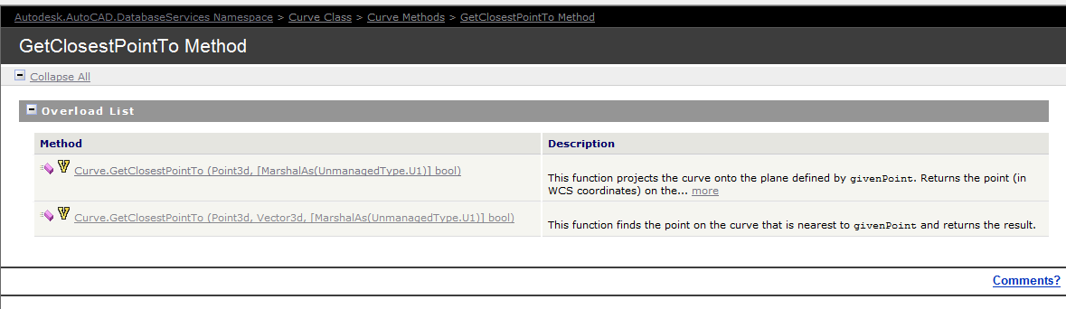
Now the following code has been generalised to the specific case of Lines and a non-descript curve (which of course is an abstract base class), but the general principles can be applied to any type of curve.
Unfortunately, the curve object exposes a method: GetClosestPointTo, which is only overloaded to accept points and not other curves. In order to deal with this rigmarole we’ll have to first, convert the curve to a `Curve3d` object which is a member of the Autodesk.AutoCAD.Geometry namespace as distinct from the Autodesk.AutoCAD.DatabaseServices namespace.
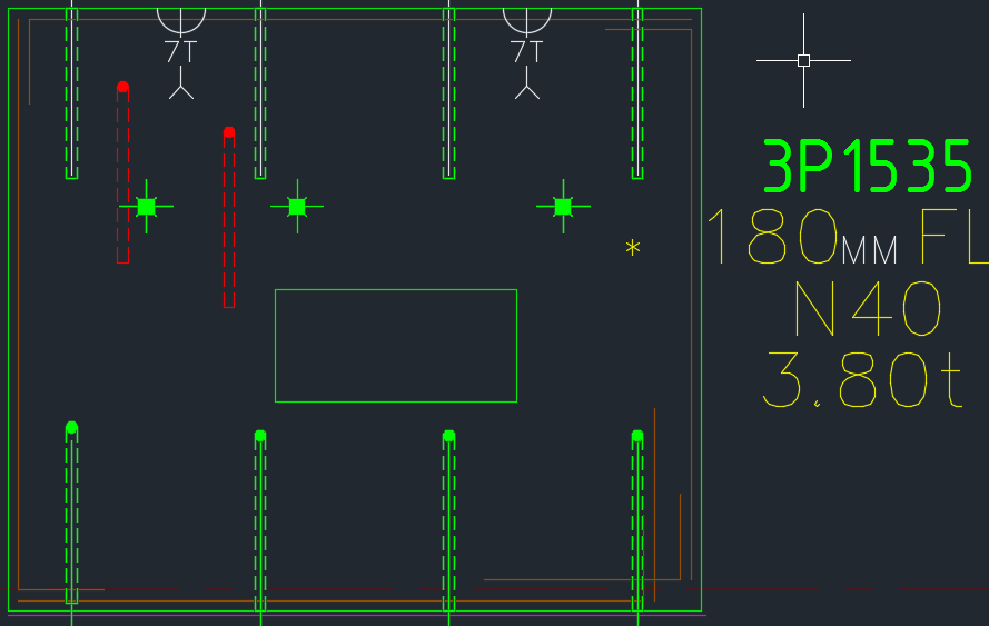
In the last part, we left off having collected the relevant Single Part Drawings that we were after. Hopefully we have applied the correct property to filter out the ‘HEA’, ‘IPE’ and ‘CC’ drawings. We will now focus on part II – extracting the distance of the bolts from the beam’s start position.
I did refactor the code a little bit, so it might not look exactly the same as the last version. The code is pretty self explanatory. But you will note that:
Here is the code in all it’s glory – simply follow the well detailed comments and it should be fairly straightforward. As always, any questions, feel free to ask.
We now have extracted the relevant information. Part III will delve into extracting this data in an Excel format. We will most likely use an OpenXML on other such library for that purpose. That post will come shortly, when I get a spare moment. Till that time, enjoy the following – or perhaps it can be left as an exercise for the user?!
This is big. Huuuuge! I’ve talked before about our ability to easily cross check between the Layout and Shop drawings. Now you can cross check from the other direction – when you are in the shop drawing, you can now check the corresponding panel which exists in the layout.
You can clearly see any differences.
So now if someone moves a ferrule or a cast in plate etc. you will be able to easily see those changes.
It could save you from some expensive errors.
Here is the demo. I hope you enjoy it!
Compare and Import Difference From the Layout Into Shop Drawings from Tek1 on Vimeo.
Features: