Tag: Design Review

  • Step-by-Step Guide to Commercial Stair Detailing (According to AS1428.1 and ABCB Housing Provisions Standard 2022)

    Step-by-Step Guide to Commercial Stair Detailing (According to AS1428.1 and ABCB Housing Provisions Standard 2022)

    If you would like me to assist with your project, please send an email to koshy@tek1.com.au with your project specifications. Kindly use ‘Raj’ as the subject header.

    Overview
    This guide provides instructions for designing and detailing commercial stairs per the Australian Standards AS1428.1 and ABCB Housing Provisions Standard 2022. These standards ensure safe and accessible stairways in commercial buildings, with specific provisions related to the National Construction Code (NCC) and the Disability (Access to Premises-Buildings) Standards.

    1. General Stair Requirements (Non-Spiral Stairs)

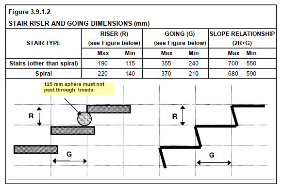
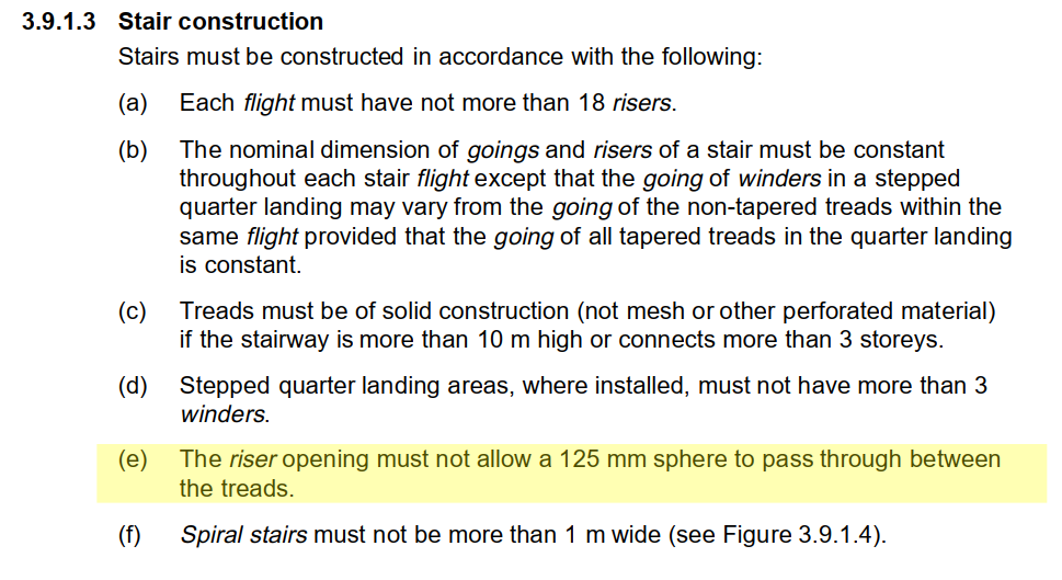
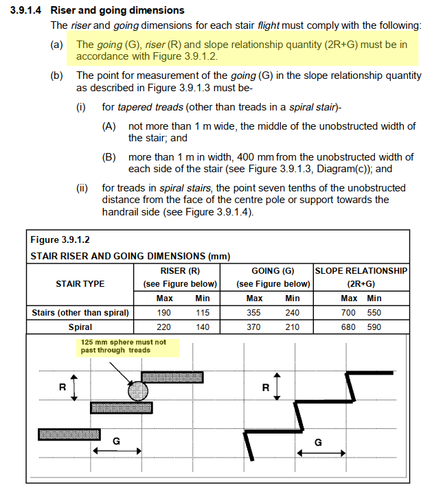
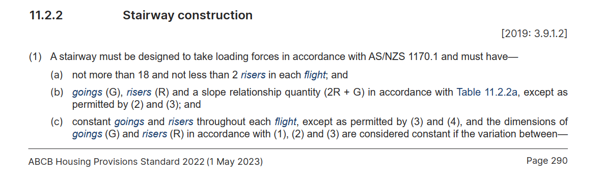
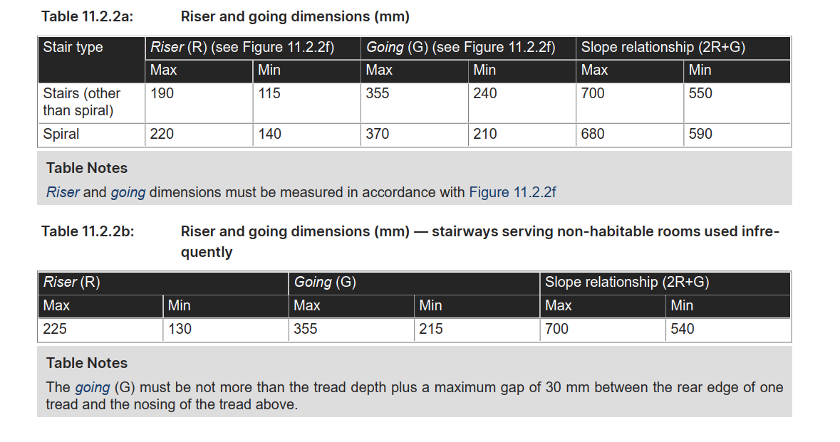
    • Riser Quantity: Each flight should have at least 2 risers but no more than 18 risers.
    • Riser Height: Must be between 115mm and 190mm.
    • Going Width (Tread Depth): Must be between 240mm and 355mm.
    • Stair Slope Rule: Follow the formula 2R+G, where:
      • Minimum Slope: 550mm
      • Maximum Slope: 700mm
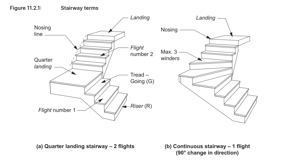
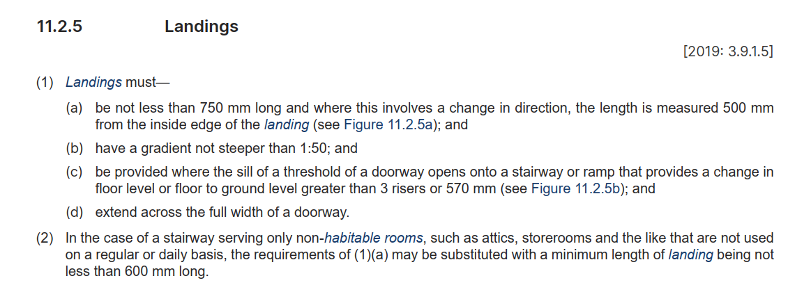
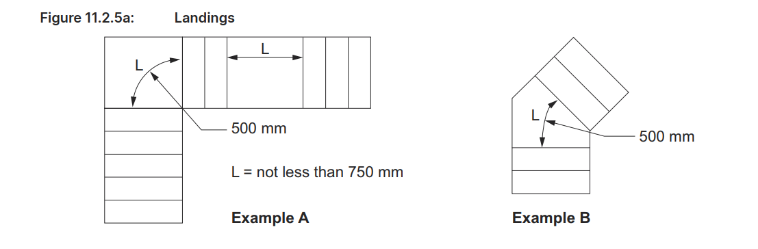
    • Landing Requirement: Landings must be at least 750mm in length. If the landing changes direction, measure at least 500mm from the inside edge of the landing​(abcb-housing-provisions…).

    2. Spiral Stairs Specifics

    • Riser Quantity: Similar to regular stairs, spiral stairs must have at least 2 risers and no more than 18 in each flight.
    • Riser Height: Must be between 140mm and 220mm.
    • Going Width: Must be between 210mm and 370mm.
    • Stair Slope Rule: Use the formula 2R+G with the following limits:

    3. Landings Specifications

    • Minimum Length: Landings must be at least 750mm in length.
    • Directional Change: For landings with a change in direction, measure at least 500mm from the inside edge.
    • Gradient: The landing slope must not exceed 1:50 to ensure levelness while allowing for slight drainage.
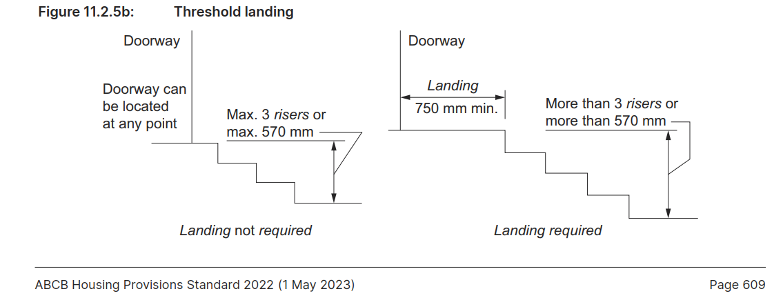
    • Threshold Requirement: A threshold landing is required where there is a floor level change of more than 570mm or three risers​(abcb-housing-provisions…).

    4. Slope and Safety Measures

    • The 2R + G formula is essential for the slope and safety of both standard and spiral stairways, ensuring each stairway is easy to ascend and descend.
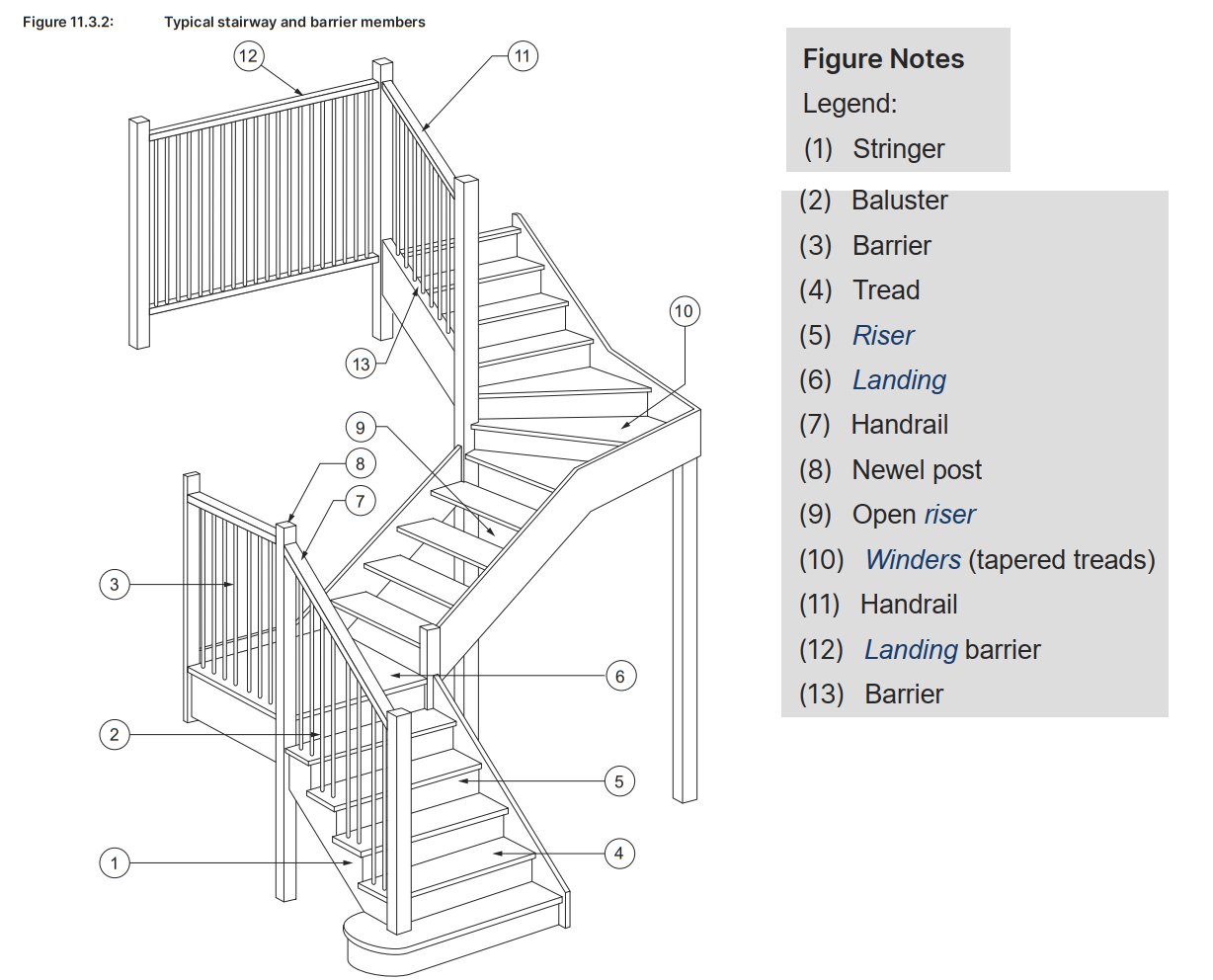
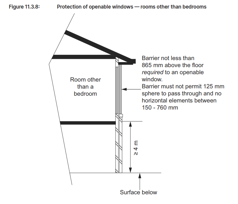
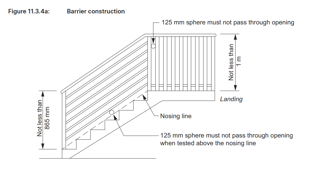
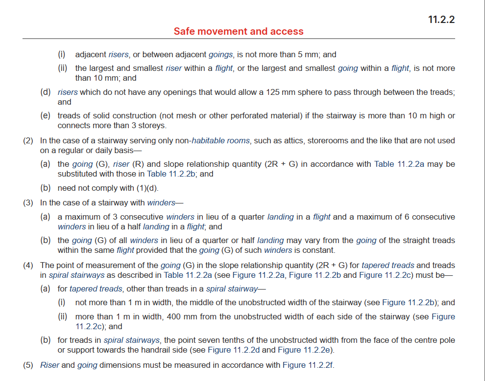
    • Open Risers: Risers must not have openings wide enough to allow a 125mm sphere to pass through, minimizing the risk of small children or objects falling through.
    • Tread Solidness: Stairs that are taller than 10m or connect more than three floors must have solid, non-perforated treads for additional safety​(abcb-housing-provisions…).

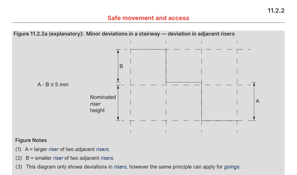
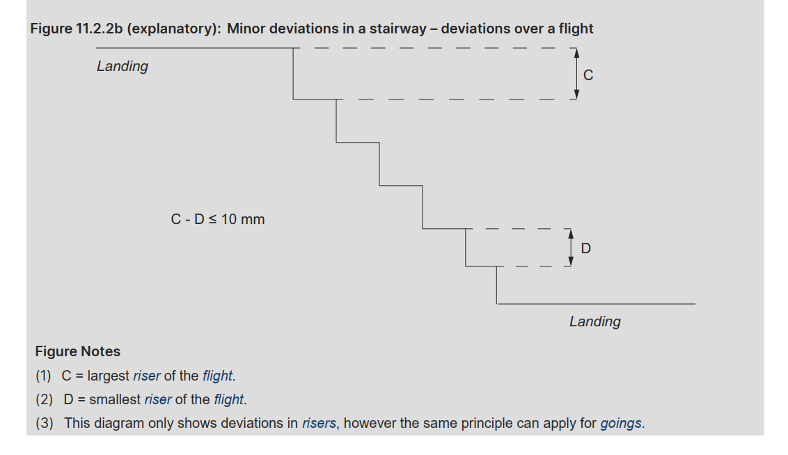
    5. Consistency in Dimensions

    • Uniformity Across Flights: All risers and goings within each flight should be consistent.
    • Permitted Variations: Adjacent risers and goings may vary up to 5mm, but the difference between the largest and smallest within a flight should not exceed 10mm​(abcb-housing-provisions…).

    6. Slip Resistance Requirements

    • Slip Resistance Testing: All treads, landings, and ramps should meet slip resistance classifications as per AS 4586. This includes:
      • Dry Conditions: Minimum P3 or R10 for treads; P3 for nosing or landing edge strips.
      • Wet Conditions: Minimum P4 or R11 for treads; P4 for nosing or landing edge strips​(abcb-housing-provisions…).

    7. Barriers and Handrails

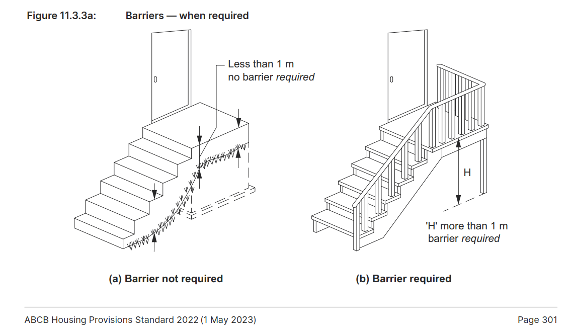
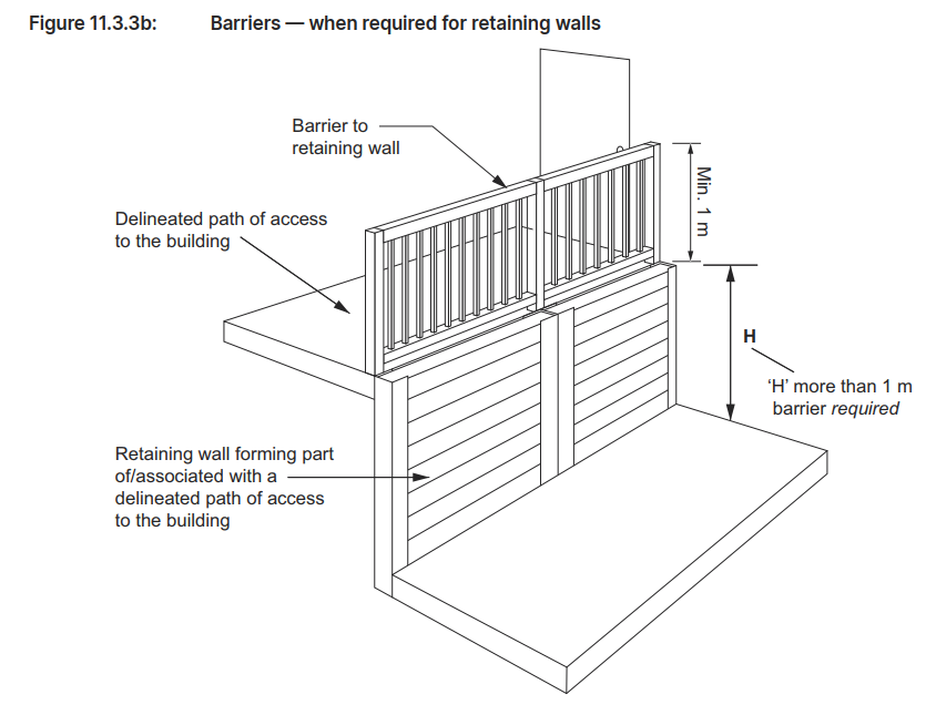
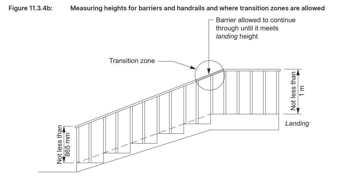
    • Barrier Height: Barriers should be at least 865mm above the nosing of stair treads, and 1m above landings and other access surfaces.
    • Handrails: Must be placed on at least one side of the stairway, running the full length of each flight and at a height of no less than 865mm.
    • Opening Limitations: No opening in the barrier should allow a 125mm sphere to pass through​(abcb-housing-provisions…).

    By following these steps, builders and architects can ensure that commercial stairs meet the safety and accessibility requirements established in AS1428.1 and the ABCB Housing Provisions Standard 2022.

  • Compliance with AS 1428.1 and BCA: Limiting Riser Openings to 125 mm in Commercial Staircases

    Compliance with AS 1428.1 and BCA: Limiting Riser Openings to 125 mm in Commercial Staircases

    If you would like me to assist with your project, please send an email to koshy@tek1.com.au with your project specifications. Kindly use ‘Raj’ as the subject header.

    When performing detailed engineering for commercial staircases and balustrades, it’s essential to ensure that all aspects comply with AS 1428.1 and the relevant provisions from the Building Code of Australia (BCA), particularly those regarding accessibility and safety. Here’s a breakdown of the critical points you must address:

    Compliance with AS 1428.1:
    1. This standard outlines the minimum technical requirements for accessible buildings. Engineers must reference the BCA to align with safety and access provisions. AS 1428.1 directs engineers to follow BCA for detailed requirements related to stair and balustrade design, ensuring all safety standards are met, particularly for disabled access.

    2. BCA 3.9.1.3 – Riser Opening Requirement:
    One of the key safety provisions under BCA 3.9.1.3 is ensuring that the riser openings on stairways are restricted. Specifically, the gap between treads must not allow a 125 mm sphere to pass through. This rule is vital for preventing accidents, such as children slipping through open risers. As a detailed engineer, you must ensure that this riser opening specification is incorporated into the technical drawings and calculations to meet safety compliance.

    3. BCA 3.9.1.4 – Riser and Going Dimensions:
    Further, BCA 3.9.1.4 provides specific dimensional requirements for stair risers and goings, as illustrated in Figure 3.9.1.2. This figure shows the maximum and minimum values for risers (R) and goings (G), as well as the slope relationship (2R + G). Engineers must adhere to these dimensions for both spiral and non-spiral staircases to ensure that the stairs are not only safe but also ergonomically comfortable for users.

    4. Critical Figures:

    Riser (R): Must be within the maximum and minimum values—115 mm to 190 mm for standard stairs and 140 mm to 220 mm for spiral stairs.

    Going (G): Must be within the maximum and minimum values—240 mm to 355 mm for standard stairs and 210 mm to 370 mm for spiral stairs.

    Slope Relationship (2R + G): Must fall between 550 mm and 700 mm for standard stairs and 590 mm to 680 mm for spiral stairs. These values ensure that stairs provide both safety and comfort.

    5. Ensuring Compliance:
    As part of the detailed engineering process, it’s your responsibility to ensure that all specifications, such as the 125 mm riser opening limit and the exact riser and going dimensions, are strictly followed in the drawings, materials, and construction processes. This involves validating these measurements on-site and ensuring they are reflected accurately in both the design and construction stages.

    In conclusion, the detailed engineering process must ensure compliance with AS 1428.1 and the BCA, particularly regarding the requirement that the riser opening must not exceed 125 mm, as outlined in BCA 3.9.1.3. Additionally, the riser and going dimensions must conform to the standards specified in BCA 3.9.1.4. By adhering to these standards, you will ensure that commercial stairs and balustrades are safe, accessible, and compliant with Australian building regulations.

  • Safety Standards in Building Design – Key Requirements for Barriers, Handrails, and Fall Prevention

    Safety Standards in Building Design – Key Requirements for Barriers, Handrails, and Fall Prevention

    If you would like me to assist with your project, please send an email to koshy@tek1.com.au with your project specifications. Kindly use ‘Raj’ as the subject header.

    1. Barriers to Prevent Falls (Section 11.3.3)

    • Purpose: Barriers are required on various elevated surfaces to prevent falls.
    • Where Required: Install barriers along stairways, ramps, balconies, and any surface where a fall of 1 meter or more is possible. (see Figure 11.3.3a).
    • Exceptions:
      • Retaining walls (unless they are part of an access path). (see Figure 11.3.3b).
      • Certain window openings covered by specific provisions. (see Figure 11.3.7 and 11.3.8).

    2. Barrier Construction Standards (Section 11.3.4)

    • Height Requirements:
      • Stairs/Ramps: Minimum 865 mm above the stair treads or ramp floor. (see Figure 11.3.4a).
      • Other Elevated Surfaces: Minimum 1 meter for landings, balconies, and similar elevated areas. (see Figure 11.3.4a).
    • Design for Child Safety:
      • Openings in barriers should not allow the passage of a 125 mm sphere, the opening is measured above the nosing line of the stair treads, minimizing the risk of children slipping through. (the opening is measured above the nosing line of the stair treads)
      • Avoid horizontal elements between 150 mm and 760 mm above the floor, as they can facilitate climbing​. (see Figure 11.3.4b).

    3. Handrail Requirements (Section 11.3.5)

    • Placement: Handrails should be installed on at least one side of stairways or ramps, providing continuous support along their full length.
    • Height: The top of the handrail must be at least 865 mm above the stair treads or ramp surface. (see Figure 11.3.4b).
    • Continuity: Handrails should be continuous without interruptions, with exceptions for elements like newel posts.
    • Exceptions to Handrail Requirements:
      • Handrails are not necessary for stairways or ramps with elevation changes of less than 1 meter, on landings, or for winders with a newel post for support​

    This guide emphasizes key elements in designing safe, compliant buildings that align with the Australian Building Codes Board (ABCB) standards for fall prevention, especially around barriers and handrails. These regulations aim to protect all building users, especially vulnerable groups such as children, from potential fall hazards.

  • Good Steel fabrication drawings saves $1,000,000: Woolooware Shores Design Review

    Good Steel fabrication drawings saves $1,000,000: Woolooware Shores Design Review

    Issue Identified:

    During the drafting phase of a recent commercial project, I encountered a critical issue involving clashes between downpipes and structural steel due to insufficient space for hydraulic piping routing.

    Discovery and Verification:

    Upon receiving architectural and structural drawings, I began modelled the structure and identified conflicts where downpipes from the gutters intersected with structural steel members.

    Initial attempts to accommodate the pipes exposed them below the ceiling, prompting me to request further hydraulic and IFC models for verification.

    Refer attached Live Model Link:

    https://app32.connect.trimble.com/tc/api/2.0/s/R0fxCRQKZX0BeTwU7YcIZKG_SqdQgG2L4xi9bsUpwwTfHjCi30NREyFv03zEbvOd

    Client Response:

    Upon submitting an RFI, the client confirmed that hydraulic piping routing had not been adequately considered in the initial designs.

    This coordination oversight posed a significant risk to the project’s integrity.

    Solution Implemented:

    To address the issue without compromising building aesthetics, I proposed raising the roof by 300mm after consulting with the client, architect, structural engineer, and hydraulics engineer. This solution was agreed upon to prevent potential wastage (58 Tons for Each Buildings, which costs around $800000 for Main Steel alone. And if we include the Purlins, Erection and other inclusive charges on site, then it will be more than a million dollar loss for both the buildings) and ensure the project’s successful completion for both Buildings (Building-C & Building-D)

    Conclusion:

    We checked the design’s aspects in every possible way to make sure that there won’t be any loss by any means to our clients.

  • Enhancing Solar Chimney Design for New Market S1 Building

    Enhancing Solar Chimney Design for New Market S1 Building

    In the recent New Market S1 building project, TEK1 participated in various design review meetings, provided numerous markups, and involved in finalizing the design. This project involved 11 flats in one of the blocks, each featuring a solar chimney on the backside of the building.

    Amendment 1: Addressing Structural Frame Issues

    Initially, the structural frame for the solar chimney was composed of two PFCs on each side running between level-1 slab & the roof. One PFC was fixed to the masonry wall with chemical anchors at regular intervals, while the other was anchored to the sides of the slabs at two different levels. However, we identified a 195mm gap between the steel PFC and the slab due to varying opening sizes for the chimney in the level-1 and level-2 slabs in the architectural layout. With this gap, it was not possible to anchor the PFC to the slab.

    Through detailed markups and discussions, TEK1 and the structural team agreed to amend the steel frame. UB members were introduced between level-1 and level-2, providing a wider support anchored on top of the level-1 slab. The PFC members were shortened to run between level-2 and the roof, with the PFC and UB connected by splice plates bolted at the top and bottom flanges. This solution effectively addressed the support issue and ensured structural integrity.

    Amendment 2: Refining the Top Frame of the Solar Chimney

    At the top of the solar chimney, the initial structural drawings provided rudimentary details. With 11 solar chimneys of varying heights and only one section view in the architectural drawings, TEK1 proposed several sketches with different options to achieve the required heights. After receiving finalization from the architect, we collaborated with the structural engineer to discuss supporting the top frame to the rafters. Stubs were introduced at the top of the rafter to secure the design.

    Ensuring Smooth Project Flow

    TEK1 ensured that these discussions and iterative markups did not disrupt the project’s workflow. While the solar chimneys were under design review, we focused on detailing other areas and supplied drawings in stages. This approach maintained the project’s momentum and avoided delays.

    If you’re interested in having TEK1 manage your project, please send a quote request to our principal, Koshy, at koshy@tek1.com.au, and specify that you want Dhileepan to manage your project. We look forward to bringing our expertise to your next venture.

  • Ascham College – Streamlining Plant Room Construction for Safety and Efficiency

    Ascham College – Streamlining Plant Room Construction for Safety and Efficiency

    In a recent project, we encountered a challenge with a plant room constructed from SHS members, featuring grating on both the floor and the roof.

    Problem 1:

    The original structural drawings specified vertical splice plates bolted together. However, these splice plates would protrude through the floor & roof gratings, creating a potential trip hazard.

    Upon identifying this issue, we notified the structural engineer, who then changed the bolted connections to site-welded connections. While this solution addressed the trip hazard, it introduced a new problem: site welding approximately 40 splices would be both costly and time-consuming.

    When this issue was discussed with the fabricator, they proposed shop welding the SHS frames into just two large assemblies for the entire plant room which they had the capacity to transport as large units. This approach significantly reduced the number of site welds required.

    Problem 2:

    However, another challenge arose: these large assemblies were to be galvanised and were too big for the galvanising bath. We consulted with the fabricator regarding the maximum size of the galvanising bath and suggested subsequently splitting the plant room assemblies accordingly. This adjustment reduced the number of site welds to around 20, making the process more efficient.

    Two primary problems were identified and solved:

    1. The bolted splice causing a trip hazard: Transitioning to welded connections resolved this safety concern.
    2. Assemblies larger than the galvanising bath: Adjusting the assembly size to fit the galvanising bath ensured the integrity of the galvanising process.

    By identifying and rectifying these issues at the planning stage, we saved significant time and money.

    If you’re interested in having me (Dhileepan) manage your project, please send a quote request to our principal at koshy@tek1.com.au and mention that you want Dhileepan to manage your project.

  • Change in Structural Design: Adapting to Highway Sign Board Challenges

    Change in Structural Design: Adapting to Highway Sign Board Challenges

    A recent project involving the installation of a static sign board on a highway required a significant change in structural design. The task involved detailing steel frames for supporting different sized sign board. However, a particular challenge arose when one of the static sign boards exceeded the maximum size allowable for its designated steel frame type.

    INITIAL DESIGN

    We promptly raised a query regarding this discrepancy with the structural engineer. The project was subsequently put on hold to address this critical issue.

    The structural engineering team responded by revising the original frame design and also the sign board’s size. This adaptive approach ensured that the structural integrity and safety of the sign board were not compromised. The revised frame design was then implemented, allowing the project to proceed smoothly.

    NEW DESIGN
  • Proactive Solutions Save Time and Money at Surry Hills Village

    Proactive Solutions Save Time and Money at Surry Hills Village

    Tek1’s proactive approach played a pivotal role in saving time and money on site by effectively addressing challenges before they escalated. When detailing a stair in an already constructed building at Surry Hills Village, Tek1 requested site measurements and images of the existing structures. Analysing the received site images, Tek1 identified potential clashes, such as the extension of an existing beam conflicting with a new column and the roof of a nearby block encroaching on the new stair’s landing.

    With this foresight, Tek1 proposed the removal of the conflicting portions, mitigating potential disruptions to the workflow. By identifying and resolving these clashes early on, Tek1 ensured a smoother construction process, preventing costly delays and rework. This proactive approach not only saved valuable time but also optimized resources, demonstrating Tek1’s commitment to delivering efficient and cost-effective solutions to its clients.