Drawings are always submitted for approval before fabrication. When any changes are given by the structural engineer or the architect, after implementing the changes, the drawings must be submitted again for 2nd approval so that the structural engineer & the architect will review & approve the drawings.
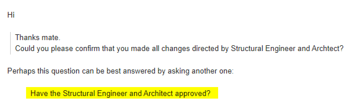
In some cases, the architect & the structural engineer skip their duty of reviewing & question the detailer whether the detailer has implemented all the changes. Refer below image for an example.
In such cases answering with a “yes” might cause trouble to the detailer & the corresponding concern in he future.
Rather than answering the question, the detailer can pose a question to the question asked like “Have the Structural Engineer and Architect approved?”. By such way, the detailer has attended to the structural engineer or the architect and also the duty to review the drawings has also been assigned once again to him.
When you are dealing with 100s, and perhaps even up to a 1000 panels per building, this can become extremely cumbersome and time consuming. Why not automate the entire process? This allows you to do things faster, to get the drawings out faster, and (hopefully) to build the panels faster, and ultimately the building faster. Speed is absolutely paramount! The faster a builder can get on and off of a construction site, the faster they can get paid. This lowers their working capital needs, and accordingly, their financing costs (however that may arise). Speed is king!
Considerations When Transporting Panels to Site
Every truck has a:
Size limitation (both length and height), as well as a:
Weight limitation (there is a maximum capacity).
Secondly, trucks have different limitations, depending on where they are transporting a panel. E.g.
Trucks passing through the CBD (central business district) have different: length/height and mass requirements compared to those that are not, furthermore, these requirements are different depending on whether the truck has a permit or not.
Let’s suppose you have the following hypothetical situation – take out a sheet of paper and pen and try and solve this by hand:
Truck A
Length limitation: 6 m
Height limitation: 3 m (but a height limit of 2.5 m in the CBD; and a height limit of 3.2 m with a permit)
Weight Limit: 12 tonnes.
Truck B
Length limitation: 4 m
Height limitation: 4 m (but a height limit of 2.5 m in the CBD; and a height limit of 3.2 m with a permit)
Weight Limit: 18 tonnes.
How on earth are you going to work out, quickly and efficiently, whether your fleet can transport the following panels:
ABC1 – Mass: 13 tonnes, Length: 5 m, Height 3 m
ABC2 – Mass: 10 tonnes, Length: 3 m, Height 2 m
ABC3 – Mass: 12 tonnes, Length: 4 m, Height 2.5 m
Problem
Are you able to transport your panels by any of the trucks in your fleet?
Which of your trucks can you use to safely transport a particular panel?
How was this particular problem was solved using the AutoCAD .net API?
I created a data structure for each of the limitations imposed by a truck.
Similarly, I created a data structure for each of the limitations imposed by each panel.
And very simply asked whether a truck and lift a panel? The output was compiled and put into an Excel report. They key method tying this all together is the `CanLift` method on the Truck class.
I used ClosedXML to combine it all together to produce a report.
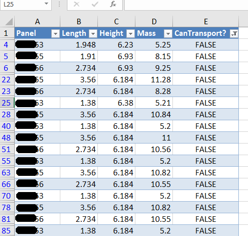
Here is an example of the results:
A sample of the report produced when running the command. This is showing all the panels that failed.
Here are the key server classes:
Summary
Tek1 has the resources and expertise in order to do Precast Panelling jobs fast and
Accurately
These are just the tip of the ice burg in terms of the checks and processes we employ.
Drawing these metal edges is time consuming and error prone.
What is the task at hand?
You have a set of 30 panels. You need to draw metal edges around the edges of all these panels. That’s easy, but it’s subject to certain specific requirements.
If it’s a Perth job then:
The metal edge can only be a maximum of 3.0m long.
Minimum distance: 0.4m long.
If it’s an Adelaide job these are the metal edge requirements:
The metal edge can only be a maximum of 2.4m long.
Minimum distance: 0.4m long.
That means you may need to do some maths. And you actually have to draw the things in. It’s a royal pain, and more than likely, you’ll make mistakes.
Video Demonstration of the Draw Metal Edges Tool
This tool obviates the need for manual calculations and drawing by hand. Chances of pick point errors and wrongly stipulating an unmakable and unorderable metal edge is there by significantly diminished.
How are you going to identify one duplicate in a sea where everything looks the same?
Duplicates are a problem – an expensive problem, especially if you are dealing with hundreds and perhaps even over a thousand panels. Somebody cocks up – usually on the client side – but how are you meant to identify it?
You could manually do it, but then that will more than likely take a long time. Or you could just employ Tek1 to do that sort of thing for you. Here is a video demonstration:
It can work for all clients with only very minor modifications. Very well abstracted out in the code.
It is super fast. Comparing the thousands of elements in each drawing takes a bit of computing power – but with smart algorithms, you can cut down the time.
It can work in the marking plan and elevation or layout. The same code, the same command, but x3 the power.
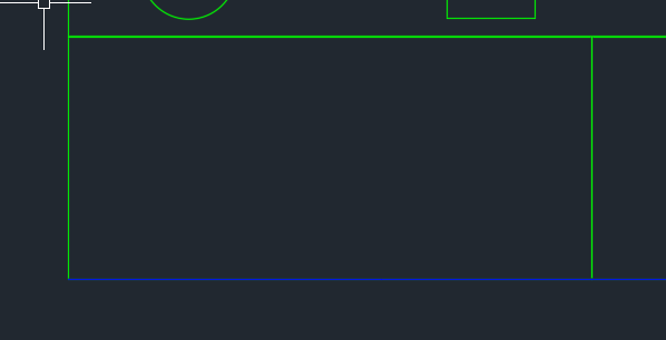
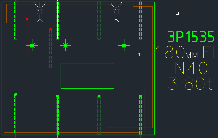
Showing a sample elevation panel with deliberately misplaced panel elements.
This is big. Huuuuge! I’ve talked before about our ability to easily cross check between the Layout and Shop drawings. Now you can cross check from the other direction – when you are in the shop drawing, you can now check the corresponding panel which exists in the layout.
You can clearly see any differences.
So now if someone moves a ferrule or a cast in plate etc. you will be able to easily see those changes.
It could save you from some expensive errors.
Here is the demo. I hope you enjoy it!
It can work for all clients with only very minor modifications. Very well abstracted out in the code.
It is super fast. Comparing the thousands of elements in each drawing takes a bit of computing power – but with smart algorithms, you can cut down the time.
It works for all sorts of edge cases – what if the panel was made up of arcs, polylines and straight lines – this plugin can handle all sorts of things. It can also handle voids.