Tag: panels

  • Checking the Transportability of Precast Panels – Using the AutoCAD .net API

    Checking the Transportability of Panels – Using the AutoCAD .net API

    It is one thing to build a panel. It is another to ensure that:

    1. It can be lifted, and
    2. It can be transported to the site.

    Here is a video demo explaining everything:

    Can a precast panel be safely transported? from Tek1 on Vimeo.

    A short primer on the importance of efficiency

    When you are dealing with 100s, and perhaps even up to a 1000 panels per building, this can become extremely cumbersome and time consuming. Why not automate the entire process? This allows you to do things faster, to get the drawings out faster, and (hopefully) to build the panels faster, and ultimately the building faster. Speed is absolutely paramount! The faster a builder can get on and off of a construction site, the faster they can get paid. This lowers their working capital needs, and accordingly, their financing costs (however that may arise). Speed is king!

    Considerations When Transporting Panels to Site

    Every truck has a:

    • Size limitation (both length and height), as well as a:
    • Weight limitation (there is a maximum capacity).

    Secondly, trucks have different limitations, depending on where they are transporting a panel. E.g.

    • Trucks passing through the CBD (central business district) have different: length/height and mass requirements compared to those that are not, furthermore, these requirements are different depending on whether the truck has a permit or not.

    Let’s suppose you have the following hypothetical situation – take out a sheet of paper and pen and try and solve this by hand:


    Truck A

    • Length limitation: 6 m
    • Height limitation: 3 m (but a height limit of 2.5 m in the CBD; and a height limit of 3.2 m with a permit)
    • Weight Limit: 12 tonnes.


    Truck B

    • Length limitation: 4 m
    • Height limitation: 4 m (but a height limit of 2.5 m in the CBD; and a height limit of 3.2 m with a permit)
    • Weight Limit: 18 tonnes.


    How on earth are you going to work out, quickly and efficiently, whether your fleet can transport the following panels:

    1. ABC1 – Mass: 13 tonnes, Length: 5 m, Height 3 m
    2. ABC2 – Mass: 10 tonnes, Length: 3 m, Height 2 m
    3. ABC3 – Mass: 12 tonnes, Length: 4 m, Height 2.5 m


    Problem

    • Are you able to transport your panels by any of the trucks in your fleet?
    • Which of your trucks can you use to safely transport a particular panel?

    How was this particular problem was solved using the AutoCAD .net API?

    • I created a data structure for each of the limitations imposed by a truck.
    • Similarly, I created a data structure for each of the limitations imposed by each panel.
    • And very simply asked whether a truck and lift a panel? The output was compiled and put into an Excel report. They key method tying this all together is the `CanLift` method on the Truck class.
    • I used ClosedXML to combine it all together to produce a report.

    Here is an example of the results:
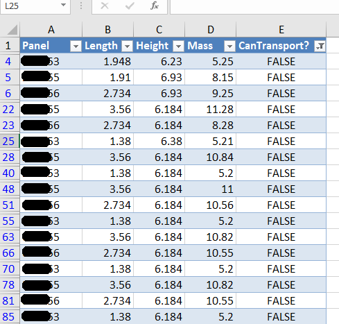
    panels that failed the transport check
    A sample of the report produced when running the command. This is showing all the panels that failed.

    Here are the key server classes:

    Summary

    • Tek1 has the resources and expertise in order to do Precast Panelling jobs fast and
    • Accurately

    These are just the tip of the ice burg in terms of the checks and processes we employ.
  • WPF User Interface for Precast Panel Comparison

    This utilises WPF to compare panels, isolate changes and make better decisions.


    See below for a demonstration:

    WPF – Eliminating Errors using Cross Checking from Tek1 on Vimeo.


  • Demo – Create Revit Panels Directly From AutoCAD Panels (Precast)

    Demonstrates the ability to transform 2D AutoCAD files into a native Revit format.

    This is a demo of my latest plug-in which demonstrates a proof of concept – i.e. a MVP (Minimum Viable Product). The programming was a little trickier than normal – because we are not using the .NET API, but the COM Interop API and the Revit API – something which I have not really explored prior to this post.

    What does it do?

    If you have drawn some panels in AutoCAD, this plugin allows you to quickly and accurately convert those panels into Native Revit walls. You can then give Architects and builders those Revit files –  otherwise it will be very difficult for them to work with AutoCAD files.

    This gives you a competitive advantage over your competition, because you can quickly and easily do it – and it makes the job of architects and builders easier – especially given the rapid push everyone’s making into BIM technologies.

    Enough talk. Here is the demo. Enjoy:

    Create Panel Walls in Revit Directly From AutoCAD – Demo from Tek1 on Vimeo.

    (I’ve made the command so that it works even when you have AutoCAD open. This allows detailers to quickly switch to Revit and AutoCAD and to delete and restart if need be. Also requiring that AutoCAD be open ensure that detailers know exactly what file they are working with and what files they are converting. It eliminates a whole lot of errors.)

  • The Signficance of the “Mould” Face in Precast Panel Detailing

    The Mould Face

    This post attempts to explain the following two questions, for those starting to learn the precast trade:

    • A lot of fancy words are thrown around. Near face. Far face. And mould face. What does it all mean?
    • How should shop drawings be marked vis-a-vis the mould face, and why should they be marked as such?

    What is a precast panel?

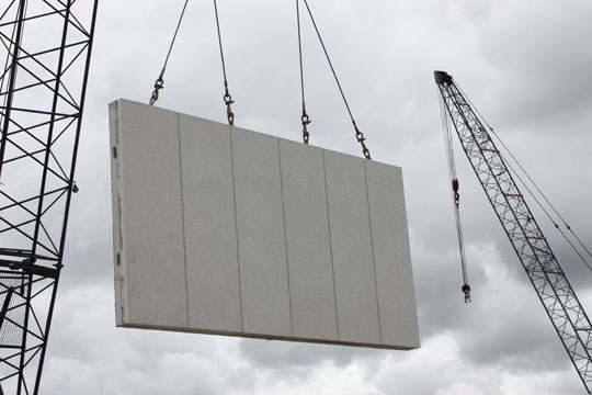
    These my friends are precast panels:


    What panels look like.


    • You can build things quickly and cheaply, if you build with precast panels. Your other option is to fabricate on site. The problem with this is that it: (i) is more expensive, and (ii) the construction is a lot slower.

    What is the mould face?

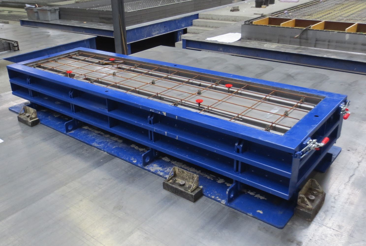
    • First you have to understand how the panels are “fabricated” (i.e. how they are made). Concrete is poured into a mould, on a table. It looks something like this:


    Showing a panel on a table, in its mould.

    So then what is the near face / far face / mould face?

    • The near face is the side of the panel which is exposed to the air. This is the face of the panel which you can see.
    • The far face (or mould face), is the face of the panel which is lying on the table.

    What is the significance of the mould face?

    • The mould face has a smooth finish (or should have one).
    • You do not want a building which has the ugly face of a panel exposed for everyone to see. The architect will be baying for your blood, and moreover it is a very costly remedy. Some precasters, in order to avoid this problem, “trowel” the near face (i.e. the face which is exposed to the air). “Trowelling” is when you smooth the surface of the panel with a tool so that it looks nice.

    When you draw a panel, you want to indicate on your drawings that the mould face is on the building exterior.

    • Why? So that the smooth side is seen by people and the ugly side is hidden from view.
    • “But won’t people on the inside of the building also see the ugly side of the panel?” you ask. Not necessarily. Most of the time, the panel is not visible on the inside of the building because the architect will put up plaster or there will be something hiding the panel from view.

    Standard Shop Drawing Practices

    • People draw elevations assuming they are looking at the near face first, rather than the far face.


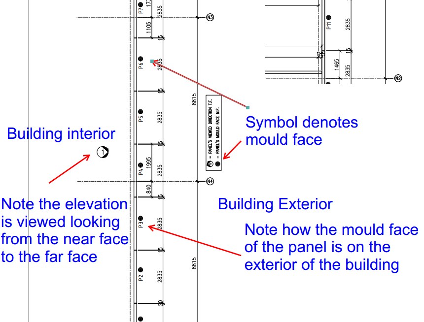
    This diagram should certainly clear things up for you:


    Shows the near face and far faces on the marking plan – also notes where the exterior of the building is.


    I hope you learned something. Any questions, please ask.

  • Transportation Issues to be aware of when detailing precast panels

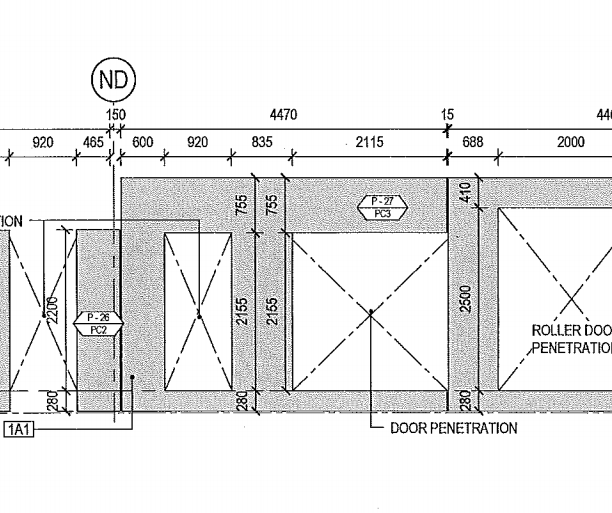
    This is a first in a series of articles I will be writing about the process of precast detailing. Suppose you get a drawing like the one below.

    Any problems you notice here?
    Any problems you notice here?

    Question: Is there anything that strikes you? That might be a potential concern?

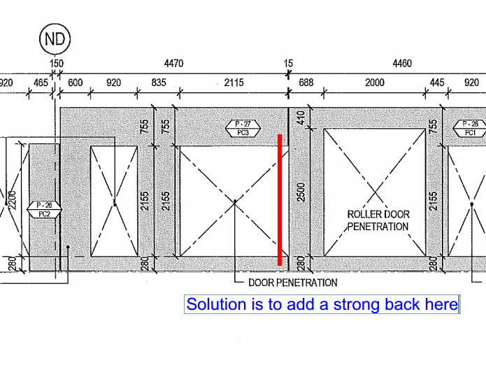
    • Take a look at Panel P – 27. And note that it kinda looks like an arch flipped on it’s side. So what’s the problem with that, you ask?
    • There is a potential issue: the panel might break. Why? Because the right hand side of the panel has no real support. If you try and put the lifters on the left hand side of the panel, when you’re trying to lift it off the table, the “legs” of this panel could break, given the size of the panel notwithstanding its reinforcing.
    • If you put the lifters on top of the panel, then the breakage issue remains – even if you do manage to successfully lift the panel without it breaking, what about lowering it into position?
    Legs of a panel. They can break off easily.

    What then is the solution?

    • Simply use a strongback. If you don’t know what a strong back is, it is simply a beam which can be used to add support to the legs. This will give the right hand side of the panel some support and sturdiness so that it will minimise the chance of breakage.
    A strong back is needed
    A strong back is needed

    Hope you learned something!