Tag: Precast Detailing

  • Changes in Consultant drawings between Quotation stage to the Project stage? You must check: here’s why…

           It is essential to cross-check the revised consultant drawings we receive against the original drawings from the Quotation stage before commencing the project because this may affect prices.

    For example, the panel break up, or the panel specs might have changed. If they have changed, this might have a material impact on price such as concrete and reinforcement cost.

    What should we do when they make changes?

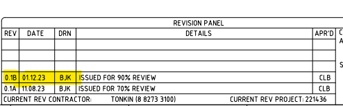
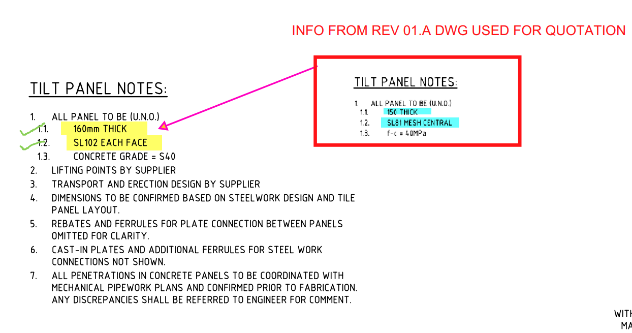
    1. Check the consultant drawing revisions and their date (between the quotation and the current stage).

    For example:

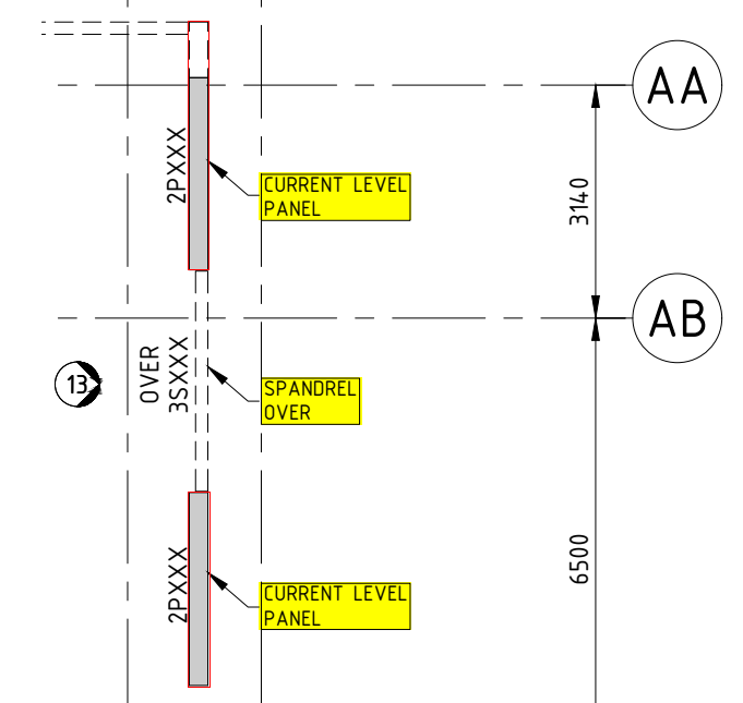
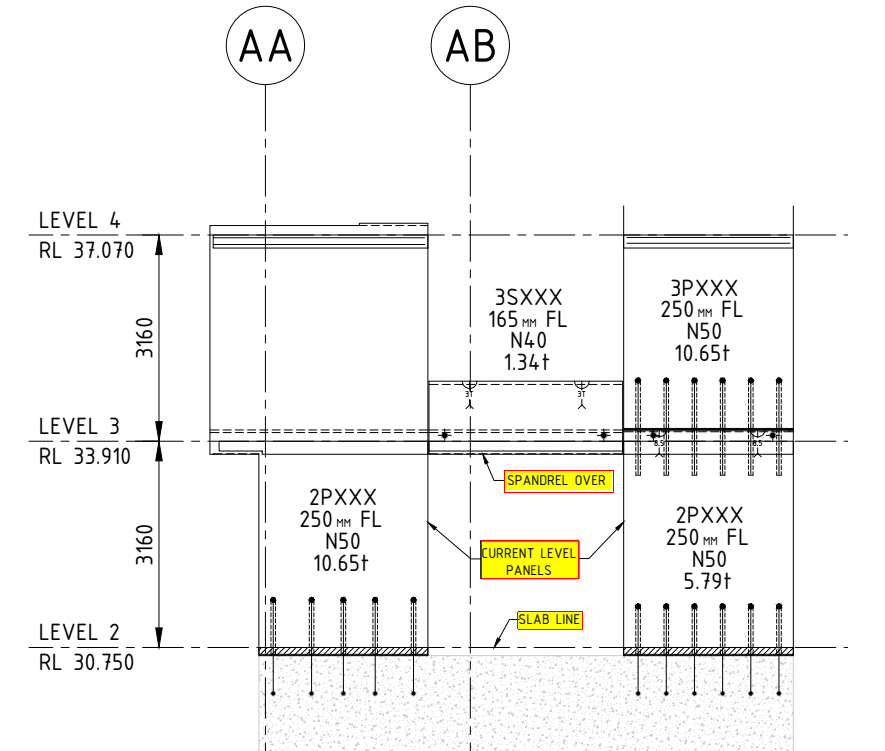
    2. Highlight the changes that occurred and mark them down in the latest structural PDF.

    For Example:

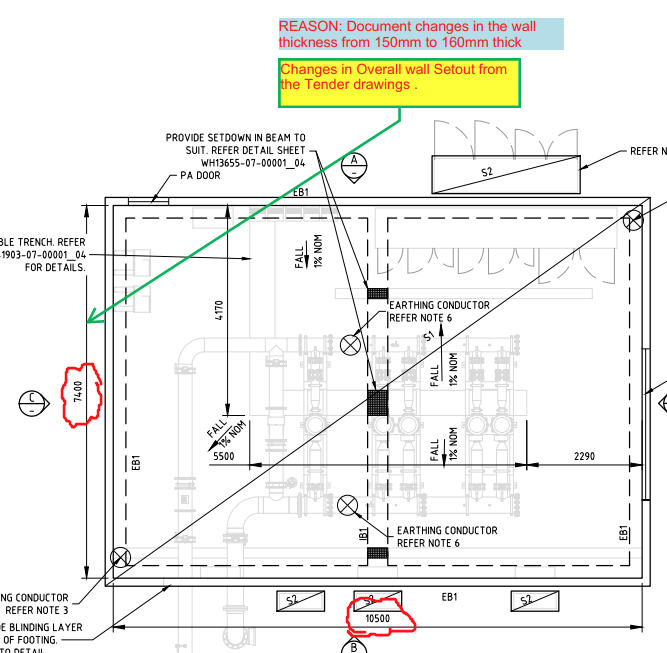
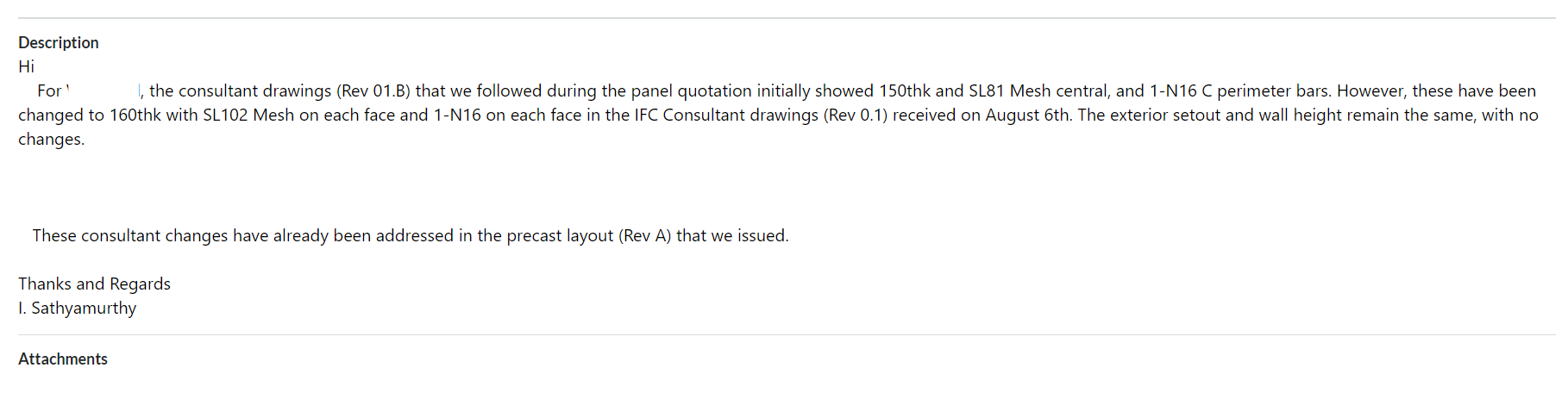
    3. Prepare a summary document report outlining the modifications.

    For Example:

    4. Inform the precast manufacturer and builder about these changes by sending the relevant information via email.

    For Example:

    Why do we need to check the consultant drawings?

         This verification process will enable the precast manufacturer and builder to re-evaluate the timeline based on the information that was previously quoted. This allows potential Cost issues that could cause confusion or delays in the project timeline to be identified and resolved early on such as

    • Cost estimation of individual precast panels, including their respective panel areas and concrete volumes, for manufacture.
    • Cost estimation of approximate reinforcement and mesh weight requirements.
    • List of cast-in items and loose items required, approximate quantities.

    What are the key factors that need to be verified in the consultant drawings from a precast perspective?

    1. Panel Thickness and Types: Verify the panel thickness and types used, as specified in the Structural Drawings.

    2. Panel Count: Confirm the panel count based on the panel split, as detailed in the Structural Drawings.

    3. Panel Transportability and Tonnage: Conduct a transportability check and verify the tonnage of the panels from our end.

    4. Panel Reinforcement:

    • Perimeter bar diameter
    • Mesh type used and its placement
    • Additional reinforcement provided in the panel typical detail
    • Reinforcement on central or either side ( specify location)
      (Refer to Structural Drawings for details)

    5. Precast Wall Pattern and Special Moulds: Verify the precast wall pattern and special moulds required, as specified in the Architectural Drawings.

    6. Panel Finish: Confirm the panel finish, as specified in the Architectural Drawings.

    7. Panel Connection Details: Verify the panel connection details, if applicable, as specified in the Structural Drawings

  • Why Should the Component Length be considered concerning Precast Panel thickness

    In one of our Projects, Audi Centre Myaree for the Client PARKD Ltd, the typical structural drawing detail represents the precast wall panel which connects to the Delta core slab with RBA20TI inserts.

    Two variations of Precast panel thickness have been used in this project: 150thk, and 200thk.

    What is the Problem?

    The Insert component RBA20TI or PTI20 are difficult to place on the precast panel face with a wall thickness of 150mm.

    Cause for the Problem: Lack of minimum concrete cover is due to component length close to the Panel thickness.

    The length of PSA Thread bar Inserts PTI20 is 148mm as per the PSA Schedule.

    Source: https://www.psa.com.au/psa-products/psa-threadbar-inserts

    The minimum concrete cover required for this project is 30mm. However, placing the component with a height of 148mm on a Panel with a thickness of 150mm results in no space for concrete cover, as shown below in Image 1

    Image 1: Plan View of 150thk Precast Panel with PTI20 Inserts on the panel face.

    Image 2: 3D view of a 150thk precast panel with PTI20 Insert. The highlighted portion in blue indicates a lack of concrete cover.

    3D Model Viewer Link for 150thk Precast Panel with PTI20 Insert:

    https://autode.sk/3QTeYrL

    Solution:

    To retain the 30mm concrete cover in the Precast panel, the PTI20 insert component needs to be replaced with PTI16, which has a length of 118mm. This will result in a 32mm concrete cover, satisfying the minimum cover criteria.

    Image 3: Plan View of 150thk Precast Panel with PTI16 Inserts on the panel face.

    Image 4: Elevation View of 150 thk panel with PTI16 Insert.

    Critical Condition To be Remeber:

    Although changing the insert size from PTI120 to PTI16. It is highly required to consider the structural strength of the connection.

    The structural strength of PTI16 with starter bars of 16 Ø is lower than that of PTI20 with starter bars of 20 Ø.

    To overcome this, it is advisable to increase the count of PTI16 insets by reducing their spacing compared to the spacing provided for the PTI20 insert.

    Image 5: PTI20 insert with a spacing of 400 centers

    Image 6: PTI16 insert with a spacing of 200 centers (The ferrule count increased to tally the structural strength)

    But in our case, since we are using inserts over the Delta Core slab, two rows of PTI16 inserts with a spacing of 150mm are to be placed vertically on the Precast Panel, as shown below

    Image 7: Detla Cover connects with the 16Ø Starter bars

    Image 8: 3D View of Precast Panel with delta Core

    3D Model Viewer Link for Precast Panel with Delta core Connection:

    https://autode.sk/3Kfc10U

    Summary:

    Length of Castin components such as Inserts and Ferrule, needs to be considered about the concrete cover and Panel thickness

    If the type of insert or ferrule changes, say from PTI20 to PTI16, to reduce its height, it is mandatory to increase the component count to maintain the structural strength.

    Thanks to Robin Hur, Structural Engineer and Project Coordinator from PARKD Ltd, for the support and critical suggestions.

  • ALTA FILAMENT PD (Precast Shop Tickets)

    TYPES OF PRECAST WALL SHOP TICKETS

    A. LITE WALL WITH DOOR OPENING :

    Sheet 1: Panel Profile, Components and their setout Placed in the Bottom In Face (BIF) of the Precast Panel.

    Sheet 2: Components and their setout Placed in the Top In Face (TIF) of the Precast Panel.

    Sheet 3: The Reinforcement Setout on the Precast Panel.

    Sheet 4: Section Detail and Order Form List for the Precast Panel.

    B. LITE WALL :

    Sheet 1: Panel Profile, Reinforcement setout, and the Components Placement on both faces of the Precast Panel.

    Since the reinforcement are not much complicated as like door opening , So they have shown in the Sheet 1 itself.

    Sheet 2: Section Detail and Order Form List for the Precast Panel.

    C. SHEAR WALL :

    Sheet 1: Panel Profile, Reinforcement setout, and the Components Placement on both faces of the Precast Panel.

    Sheet 2: Section Detail and Order Form List for the Precast Panel.

    D. SHEAR WALL WITH WINDOW OPENING :

    Sheet 1: Panel Profile, Reinforcement setout, and the Components Placement on both faces of the Precast Panel.

    Sheet 2: Section Detail and Order Form List for the Precast Panel.

    SITE IMAGES

  • TYPES OF SERVICE DRAWINGS USED FOR PRECAST DETAILING

    Types of Service drawings:

    • Crane drawing
    • Lift drawing
    • PT drawing (Post tension)
    • Mechanical service drawing
    • Electrical service drawing
    • Fire service drawing
    • Steel detail drawings
    • Hydraulic service drawing
    1. Crane drawings
      1. Refer crane drawings for loading platform location, Crane tonnage & its relevant circles and other crane related data’s. (Refer Fig.01)

    Fig .01 (Ref. Crane drawing)

    2. Lift drawings

      1. Refer these drawings for lift door opening size & set-out, lift door fitment rebates, landing RL’s, penetrations and rebates for call buttons & indicators, service hatch openings, Unistrut’s locations, lifting eye locations and loading factors, switch cut-out on final floor and other lift related data. (Refer Fig.02)

    Fig .02 (Ref. Lift door & penetration details)

    3. PT drawings

      1. Must refer these drawings for PT tendons passage location. Wherever the PT tendons passing through the precast we must provide block-outs to suit accordingly. The nominal size of block-outs for PT to pass through as per engineer requirements. If not shown on any drawings, we need to raise RFI (Request for information). (Refer Fig.03)

    Fig .03 (Ref. Post tension drawing- PT)

    4. Mechanical service drawings

      1. Refer these drawings for mechanical openings in slabs & walls. Mainly for duct works, garbage chutes, kitchen exhaust chutes, stair pressurization openings, etc. (Refer Fig.04)

    Fig .04 (Ref. Mechanical service drawing)

    5. Electrical service drawings

      1. Refer these drawings for electrical penetration requirements in slabs & walls. Mainly for communication, power and other electrical related accessories to pass through. (Refer Fig.05)

    Fig .05 (Ref. Electrical service drawing)

    6. Fire service drawings

      1. Refer these drawings for Fire service penetration requirements in slabs & walls. Mainly for fire hydrants, sprinkler system and its pipe accessories to pass through. (Refer Fig.06)

    Fig .06 (Ref. Fire penetration drawing)

    7. Steel detail drawings

      1. Refer these drawings for Steel to precast connection details. Mostly if some connection like this present, we will get intimated beforehand. (Refer Fig.07)

    Fig .07 (Ref. Steel drawing)

    8. Hydraulic service drawings

      1. Refer these drawings for Hydraulic service penetration requirements in slabs & walls. (Refer Fig.08)

    Fig .08 (Ref. Hydraulic service drawing)

  • GROUT TUBE WITH DETAILS

    GROUT TUBES:

    • Grout Tubes are hollow components and are made of plastic or thin sheet metals.
      (Refer Fig.01)
    • Grout tubes are cast into precast elements which create a void to locate and connect the elements (between two precast elements or in-situ to precast elements) together using starter bars or dowel bars.
    • Once the elements are in position, the grout tubes are filled with grouting material and locking the elements in position.

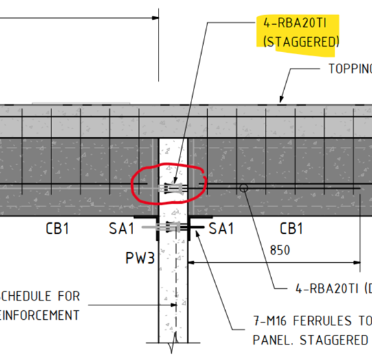
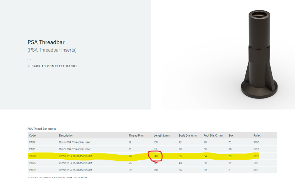
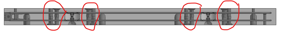
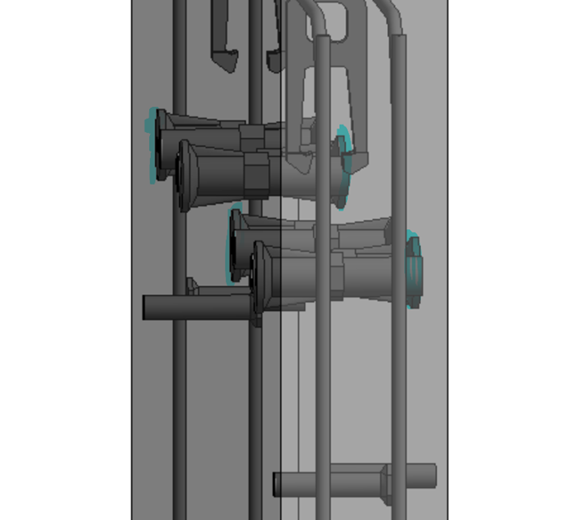
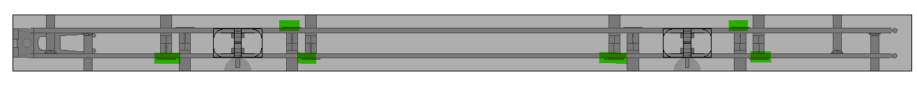
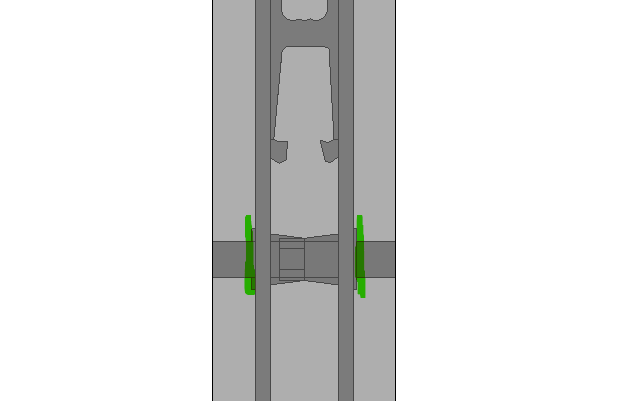
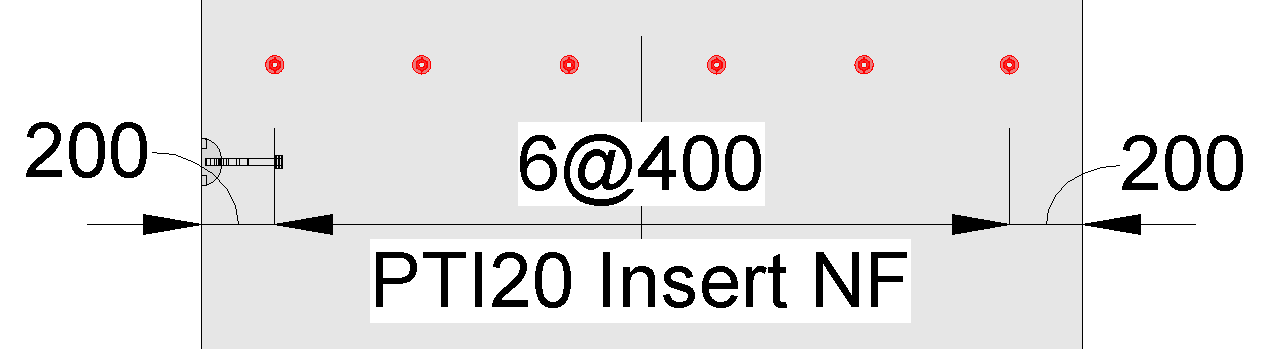
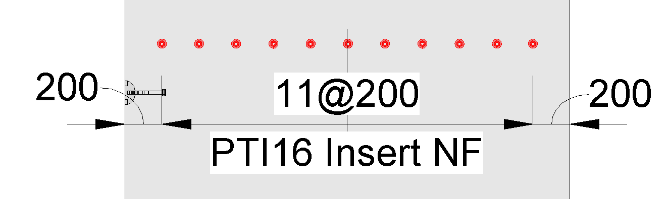
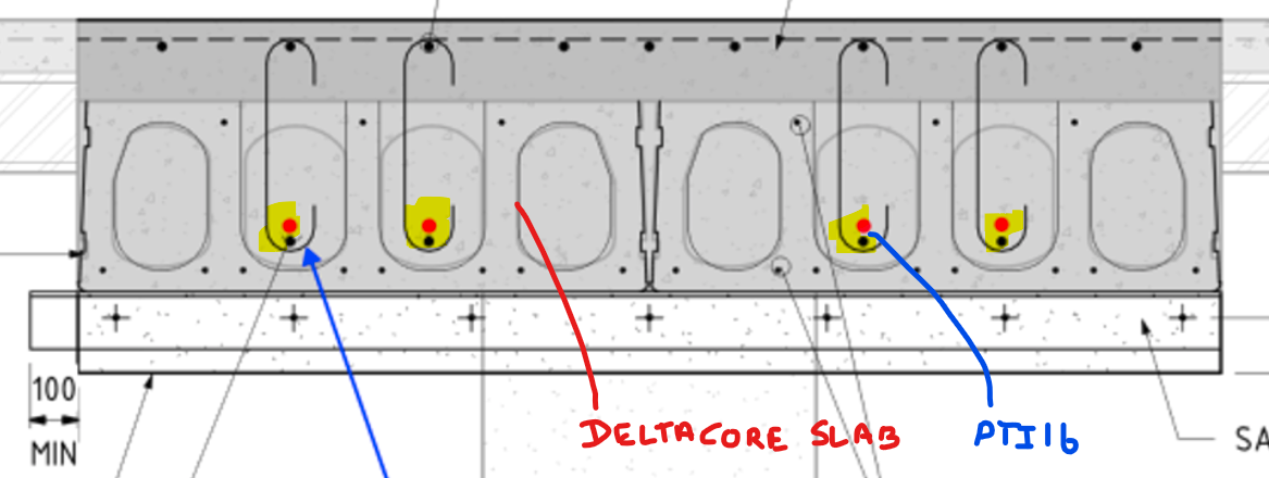
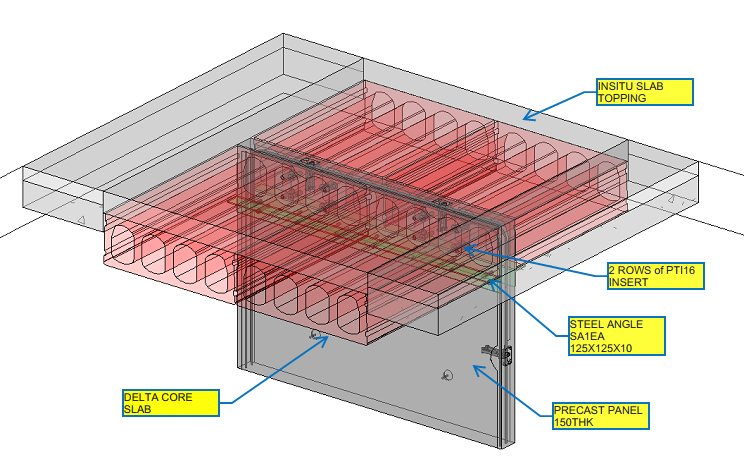
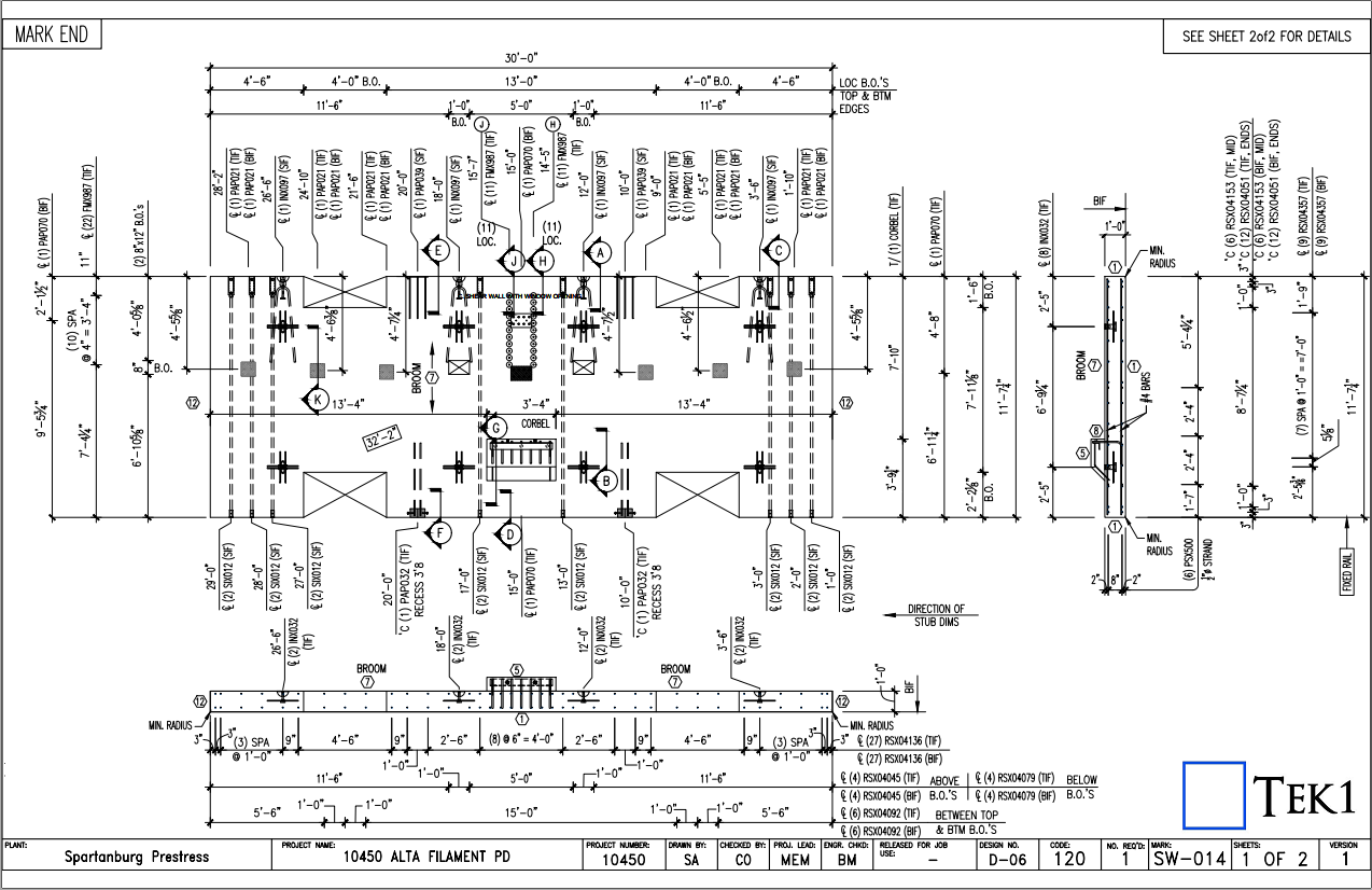
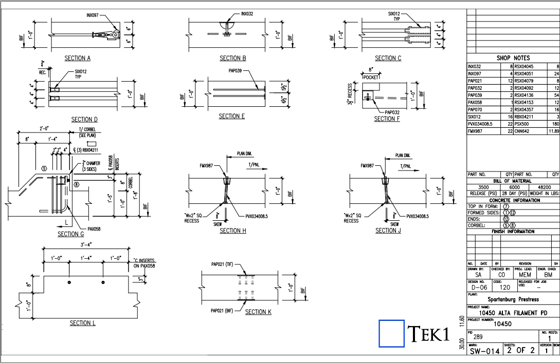
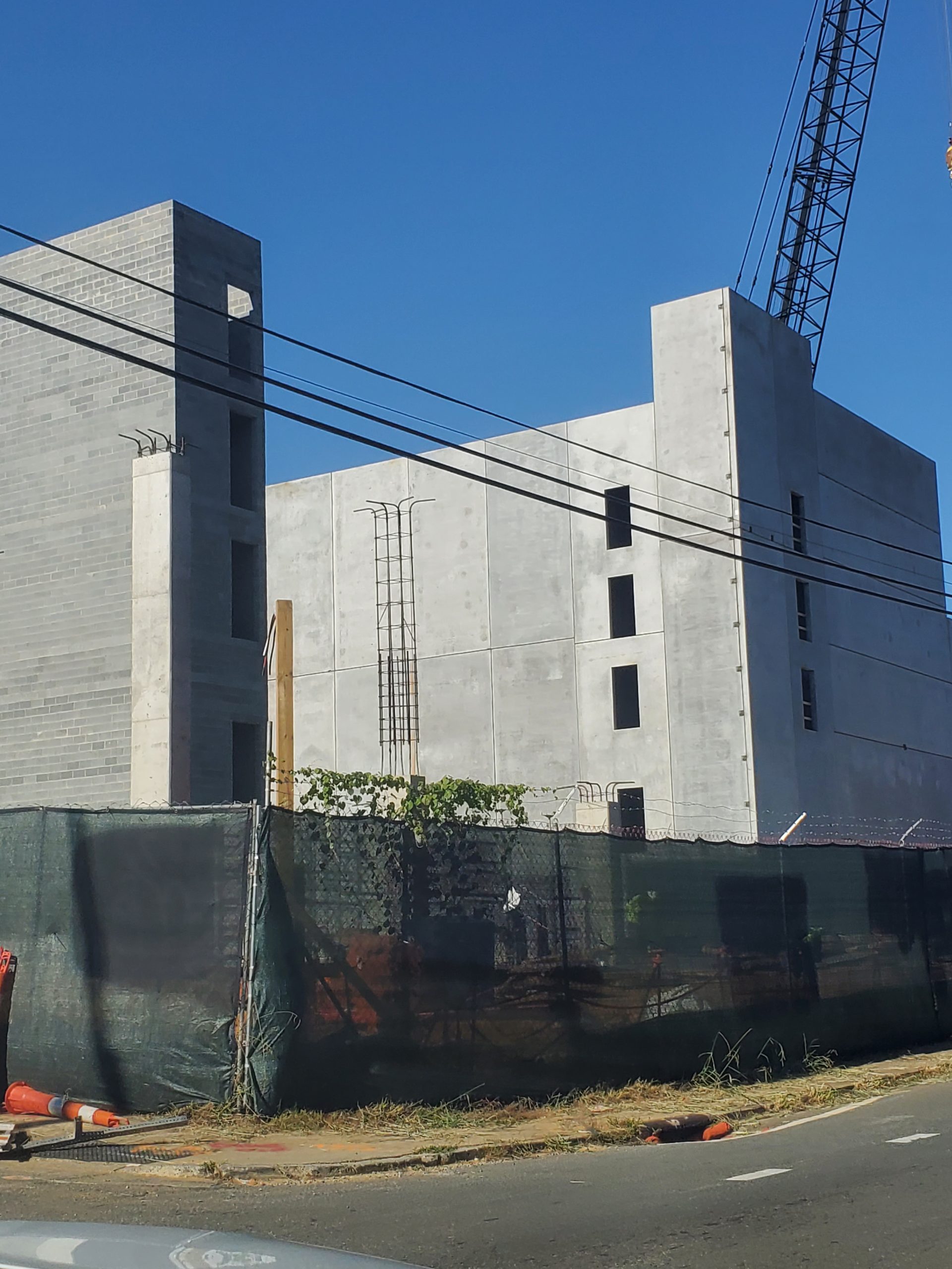
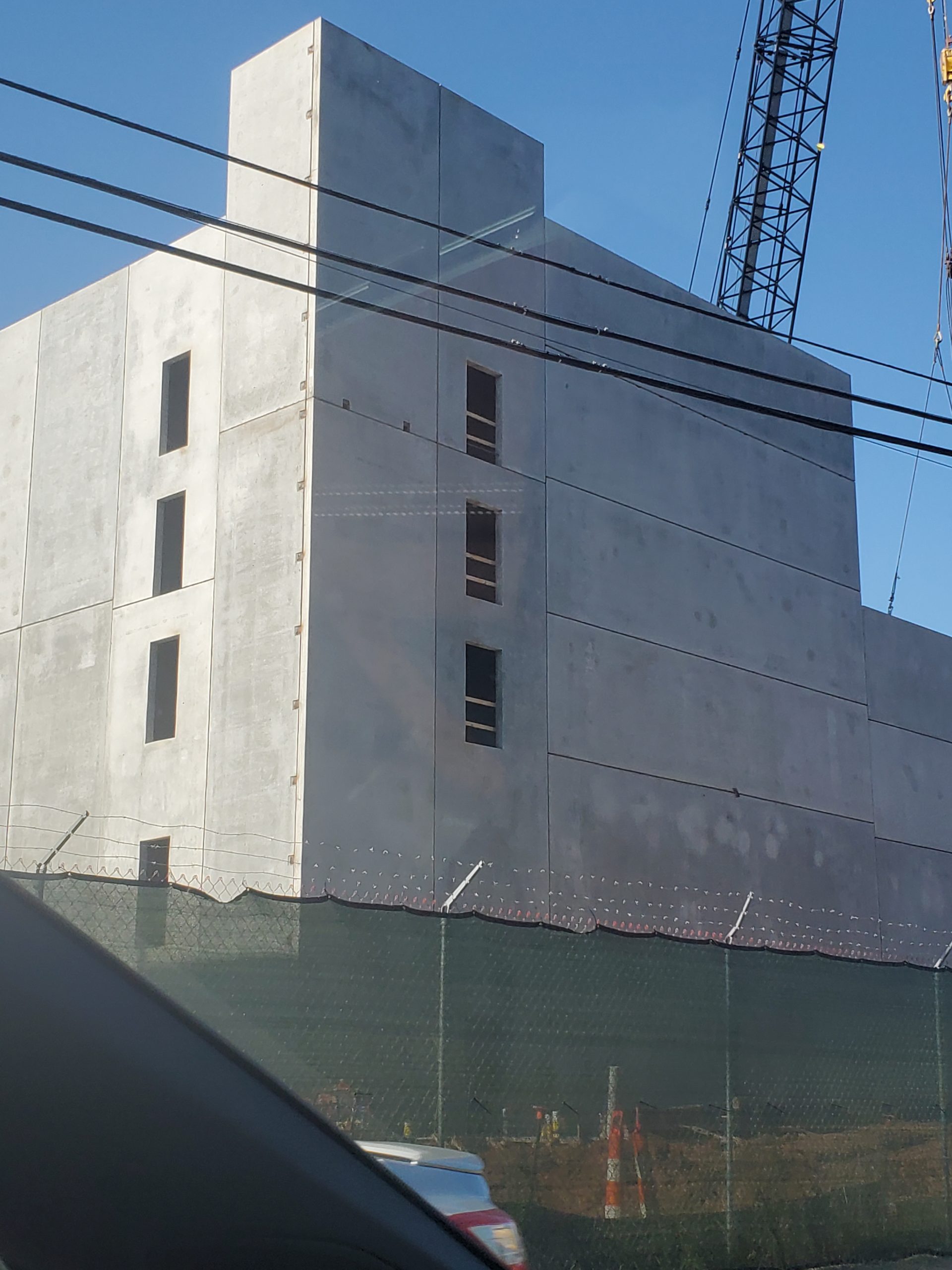
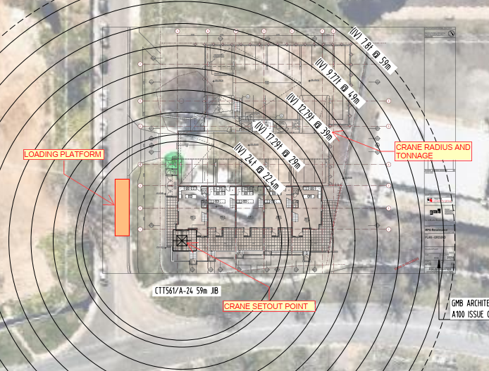
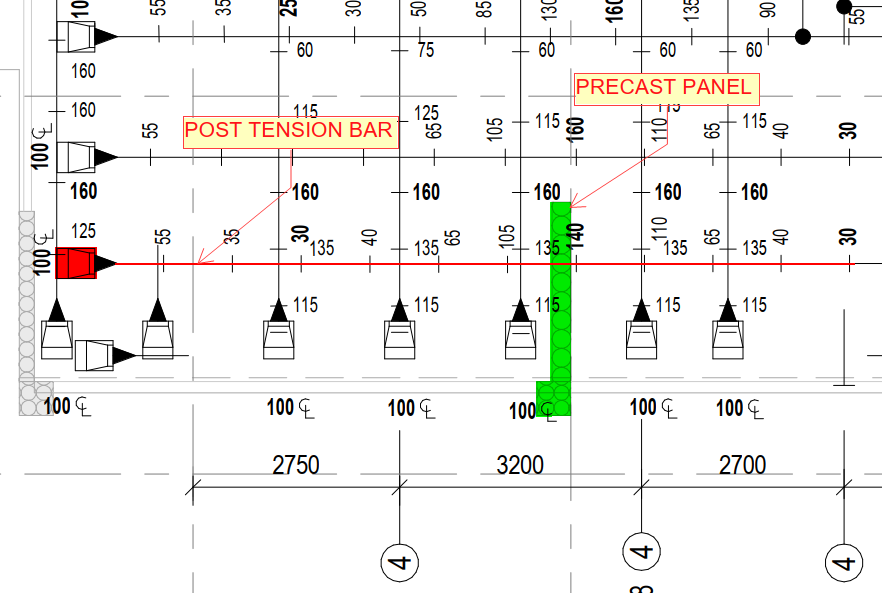
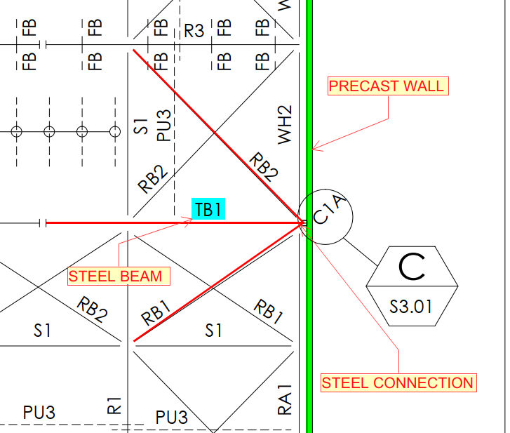
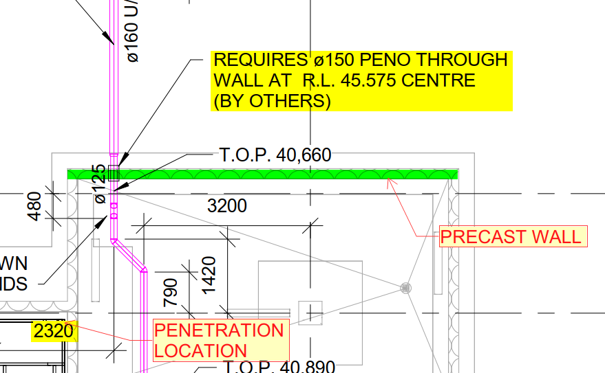
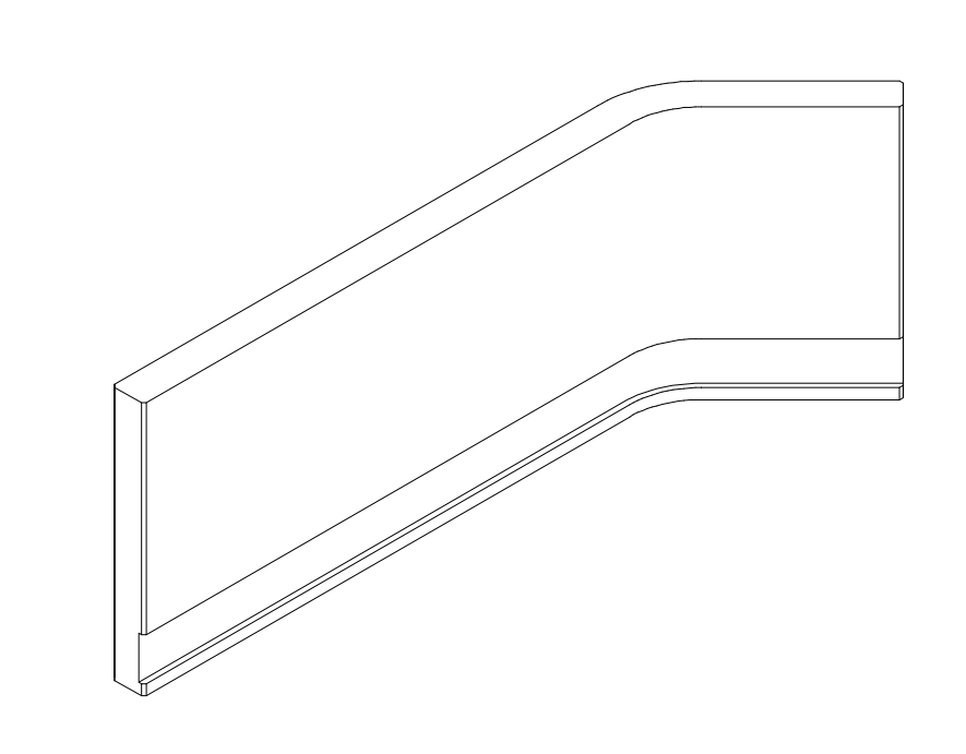
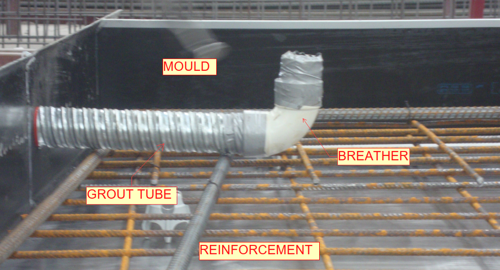
    Fig.01 (Sample bottom Grout tube with breather)

    Purpose of Grout tubes:

    • Grout tubes are used in the construction of precast concrete buildings for connecting elements like walls, tilt-up panels, beams, columns, etc.
    • It will help to increase the strength and durability of the precast or in-situ elements.

    General details for Grout tubes

    1. Hollow components with spiral designs or key ways in its walls
    2. Selection of grout tubes based on dowel size
    3. Alternatively, NMB splice sleeves or penetrations can be used or dowel bars can be directly casted if having rebar’s arrangement congestion
    4. Grouting materials must be filled for Load bearing areas and voids will be present for NLB (Non load bearing) portions.
    5. Must not clash with other components in precast (Cast in plate, Lifter, Lig-cage, lig-cage hooks, Prop, Grooves, Ferrules and etc.) – Refer Fig.02
    6. Face of breather must be inside of building and must have access, must not be placed where sequential grooves or architect patterns present.
    7. If breather has no access must provide breather extent to where the access is possible (not required when it is NLB)
    8. Must have a minimum gap of 200mm with other components especially lifters & block-outs (this value can be modified, if having difficulties to maintain that gap)
    9. Avoid the Grout tube placement near to window & major openings (wherever possible)
    10. Grout tube must be placed within 300mm from panel edge. (But can be modified if having any difficulties.)

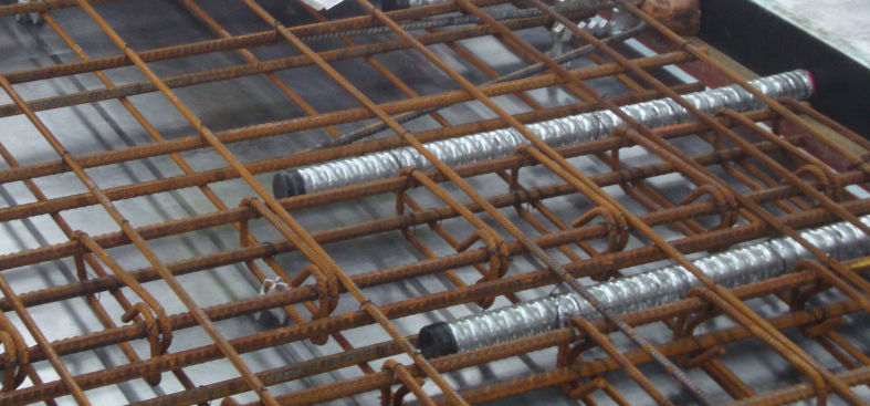
    Fig.02 (Sample Top Grout tubes)

    Advantages:

    • Lightweight and easy to process
    • Available in a range of sizes
    • It will help to reduce the construction time on site
    • Easy to connect with precast or in-situ elements

    Disadvantages:

    • The huge amount of grout tubes needed to fill up the duct in order to secure the connection between the precast wall or in-situ.
  • DOWEL BAR WITH DETAILS

    Dowel bars:

    • Dowels are short straight steel bars and also cogged bars, used to provide mechanical or structural connection between two precast elements or in-situ to precast elements.
      (Refer Fig.01)

    (Fig.01) Dowel bars

    Purpose of Dowel bars:

    • Dowel bars used to maintain the horizontal and vertical alignments of slab and precast panel. (Ref Fig.02)
    • Dowel bar connection used to transfer the loads between two concrete elements or two precast elements or precast to in-situ elements. (Refer Fig.03&04)
    • Dowel bar is used to extend the structure easily with small drilling to insert the steel for the extension of the structure.

    General details for Dowels:

    • Dowel bar is a steel rods with spiral outer design. (Refer Fig.01)
    • Used in all the locations where Grout tubes are required.
    • Selection of Dowel based on Engineer requirement.
    • Dowel can either be black finish or galvanized finish.
    • Black finish for load bearing dowels and galvanized finish for NLB (non-load bearing) dowel. (It may be varied).
    • Alternatively, bars connected into NMB splice sleeves can be used. Also, starter bars can be casted into panel.
    • Plastic tube will be placed over upper half of dowel. And 20mm compressible cap will be placed over the top of the dowel bar for NLB (non-load bearing) portions whereas grouting material will cover the entire dowels for LB (Load bearing) conditions.
    • Dowels must be positioned within Grout Tubes with minimum amount of clearance on precast walls or slabs.

    Advantages:

    • It is reducing the corner cracking.
    • It will reduce joint faulting.
    • Dowel bar is also used to reduce the deflection and stress.

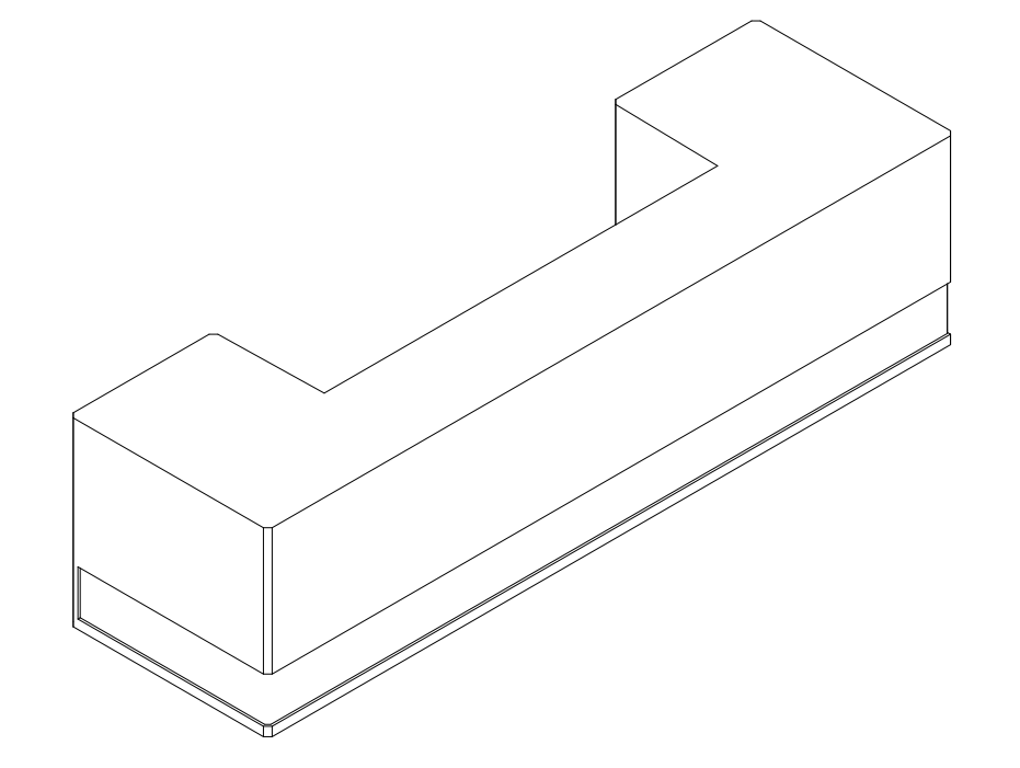
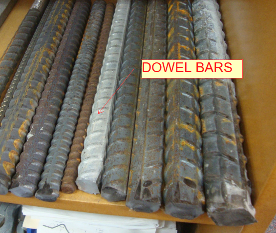
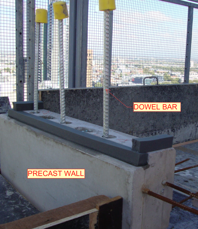
    (Fig.02) Precast wall connection

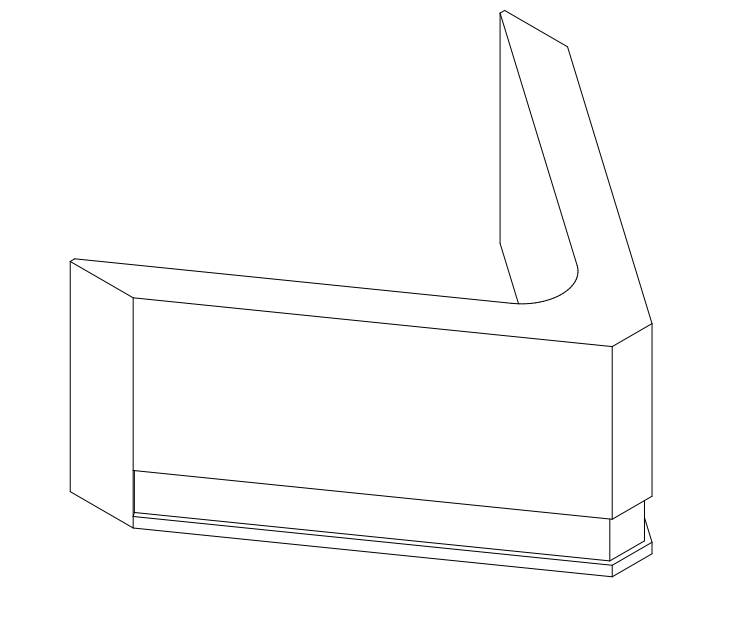
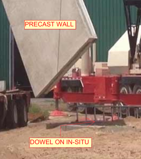
    (Fig.03) – Precast to in-situ connection

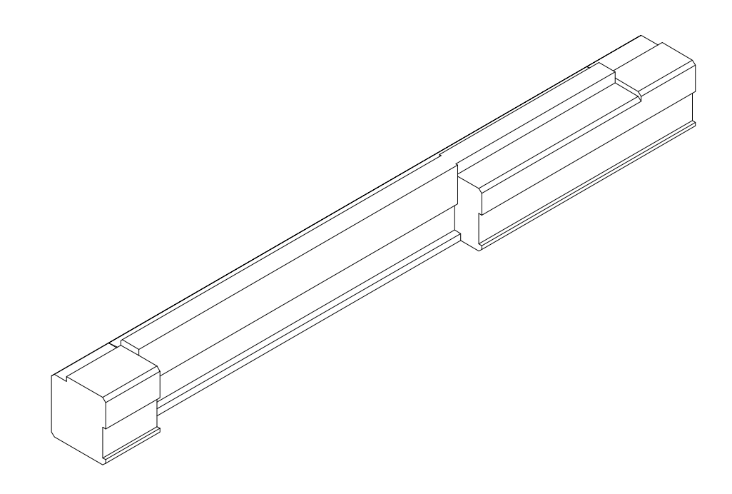
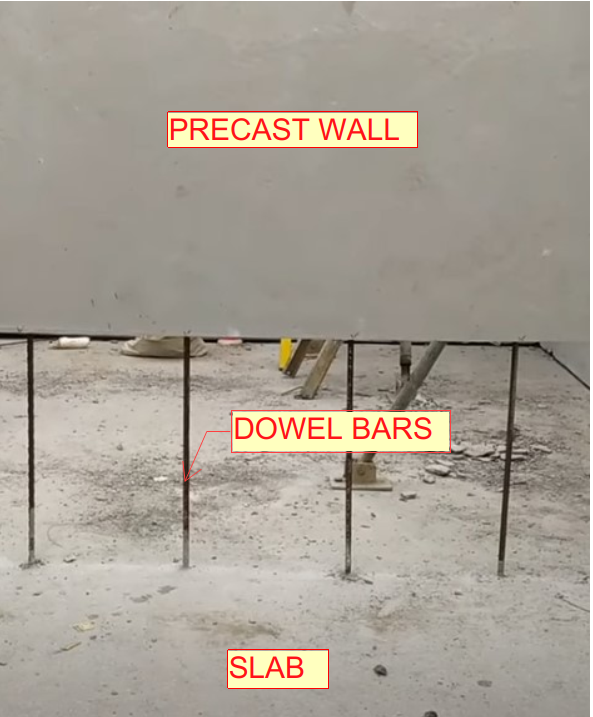
    (Fig.04) – Precast to slab connection

  • ARCH STAIR PLAN DETAILS AND DRAWING STUDY

    1. Stair or fire stair drawings are used to find the stair landing RL, landing slab set-out (X-axis distance), fire penetrations and stair pressurization riser details.
      (Refer Fig .01 & 02)
    2. This drawing package are provided by architect separately in arch consultant drawings.
    3. The main things for this drawing are to take the value of stair landing RL’s, Door and opening sizes.
    4. If any mismatch with consultant arch drawing, we have to raise RFI (Request for information) and confirm it. (Most of the cases we need to follow as per stair drawing package only. If we need to raise RFI (Request for information), make sure and cross check issuing date & other references from drawings).
    5. Stair Landing & its mid landing RL’s will be taken from Architect Stair section drawings. If they not provided, then we have to check those RL’s in arch concrete plans.

    ARCHITECTURAL STAIR PLAN (Fig .01)

    ARCHITECTURAL STAIR ELEVATION SECTION (Fig .02)

  • VARIOUS SPANDREL PROFILES

    • Spandrel profiles are designed based on architectural aspects on Elevation purpose.
    • When doing this kind of profiles, it’s challenging and more interesting to achieve.
    • And also, it will help to improve our drawing knowledge and skill.
    • We handled and come across different types of precast spandrel profiles as per below,
    1. Spandrel with straight profile
    2. Spandrel with curve profile
    3. Spandrel with curve & triangle profile
    4. Spandrel with L shaped profile
    5. Spandrel with U shaped profile
    6. Spandrel with V shaped profile
    7. Beam type spandrel1. Spandrel with straight profile (Ref. Fig.01)

    Fig.01

    2. Spandrel with curve profile (Ref. Fig.02)

    Fig.02

    3. Spandrel with curve & triangle profile (Ref. Fig.03)


    Fig.03

    4. Spandrel with L shaped profile (Ref. Fig.04)

    Fig.04

    5. Spandrel with U shaped profile (Ref. Fig.05)

    Fig.05

    6. Spandrel with V shaped profile (Ref. Fig.06)

    Fig.06

    7. Beam type spandrel (Ref. Fig.07)

    Fig.07

  • PURPOSE OF SPANDREL OVER ON MARKING PLAN

    • When preparing marking plans, we need to show all spandrels set-outs on the plan layout that are fixing into the slab over. (Refer Fig.01 & 02)
    • It will help to find out which spandrel comes at level above.
    • While scheduling the current level panels, mean time it will helps to scheduling the above level spandrels.
    • And, it will help to manufacturing and erecting the spandrels with lower-level panels at same time.
    • For site crews, they also aware when pouring slab and erecting panel sequence without any time delay on site with reference marking plan.
    • It will reduce time consumption to plan for both manufacturing and erecting panels.
      Fig. 01 (Snap for Reference Marking Plan)


    Fig. 02 (Snap for Reference Elevation)