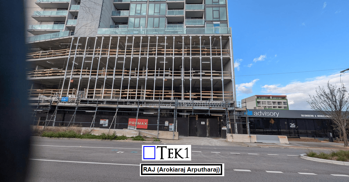
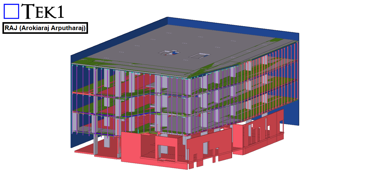
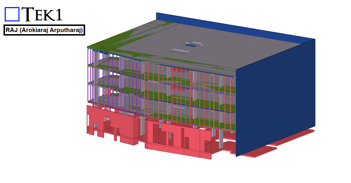
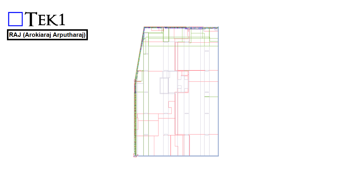
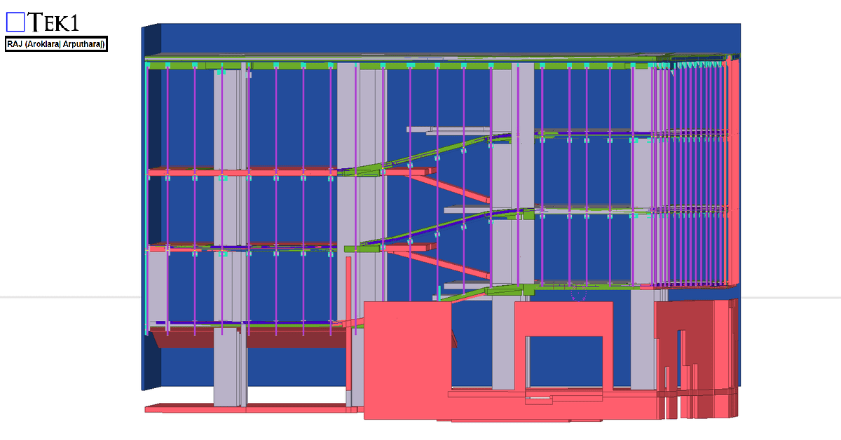
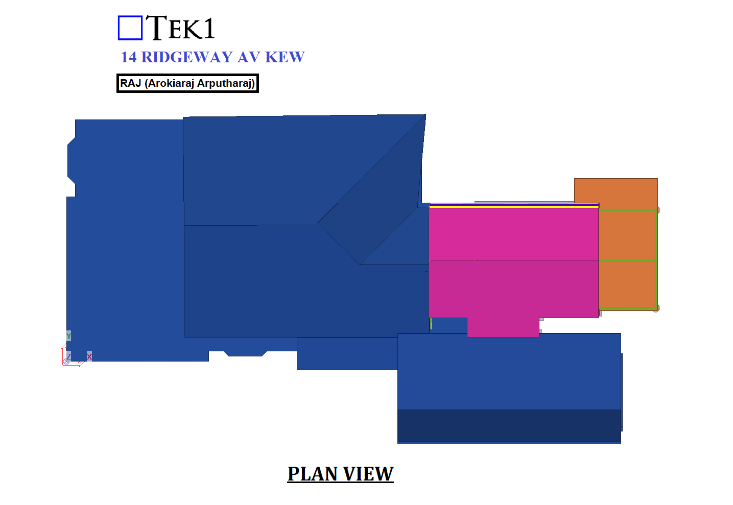
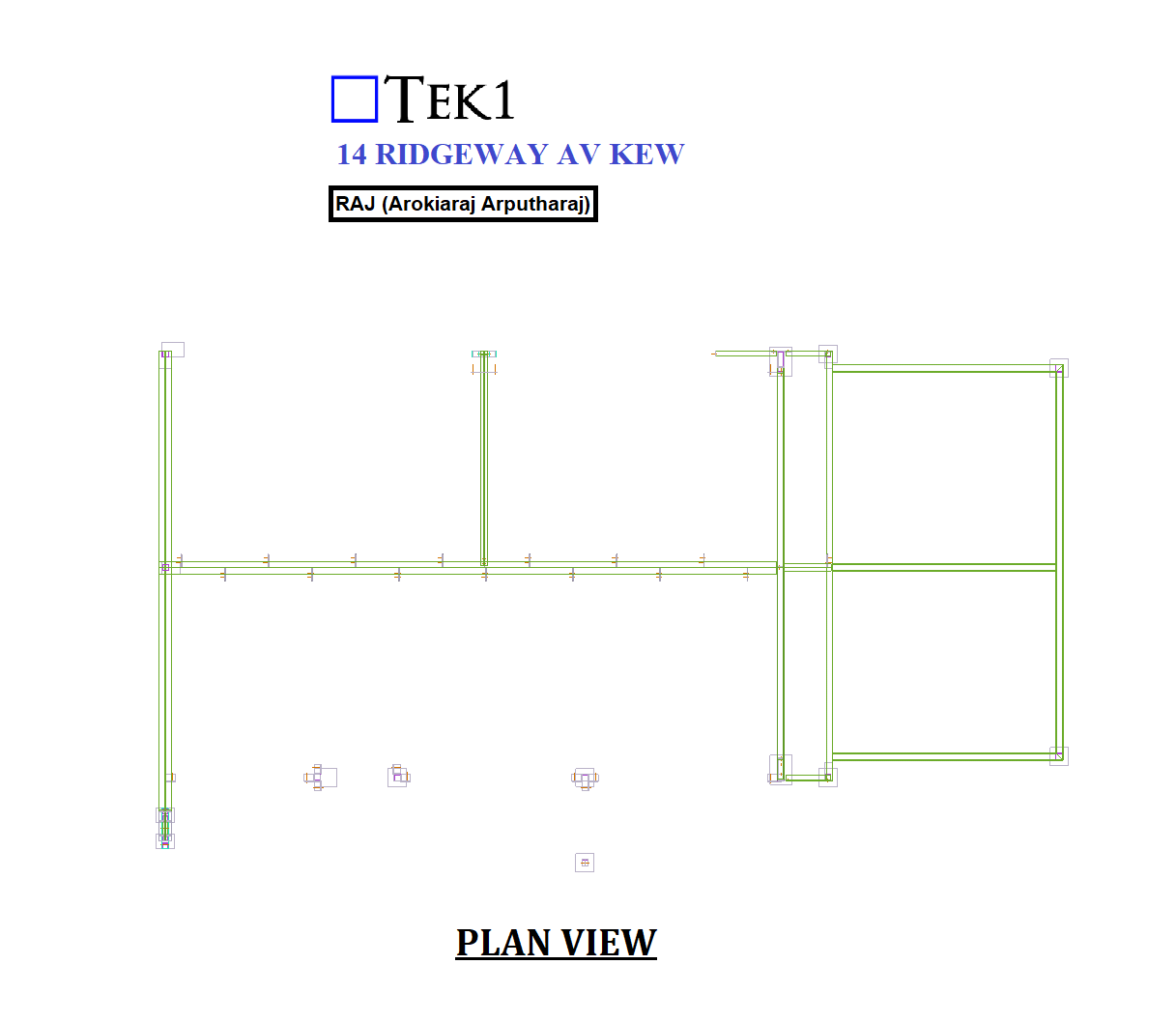
For the 27 Scott Street project, the client requested that the façade posts be installed with sufficient clearance so that the fixing anchors do not clash with the PT cable lines.
We carefully followed the client’s requirements and coordinated the design to ensure that the anchors clear the PT cable lines. The steel was successfully erected without any issues.
We would like to thank the client for giving us the opportunity to be part of this project.
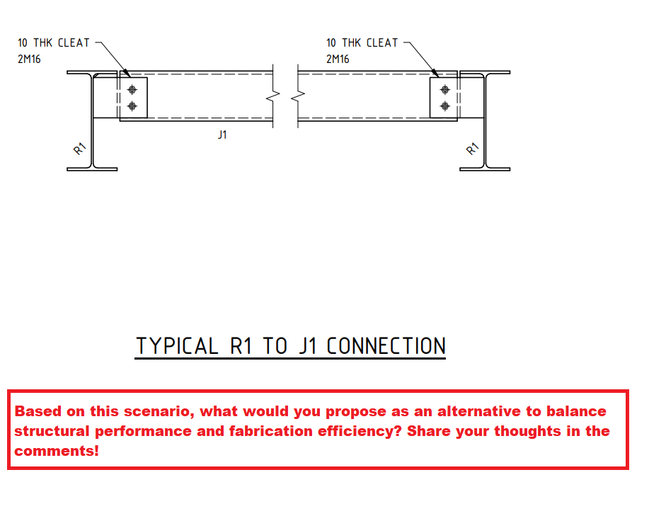
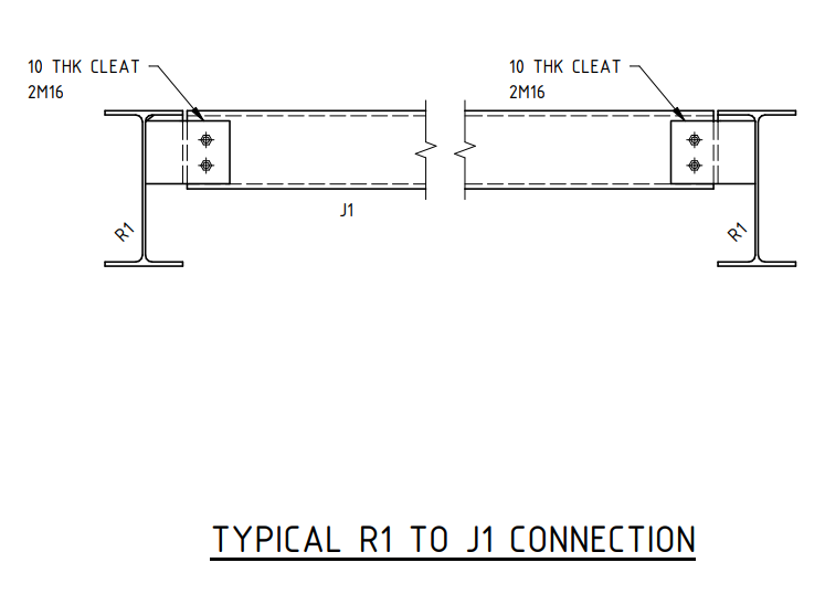
Based on this scenario, what would you propose as an alternative to balance structural performance and fabrication efficiency? Share your thoughts in the comments!
Introduction
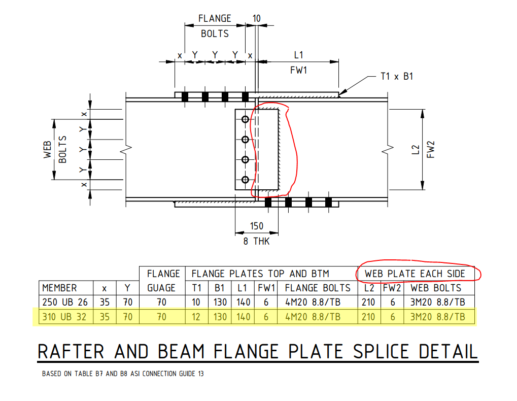
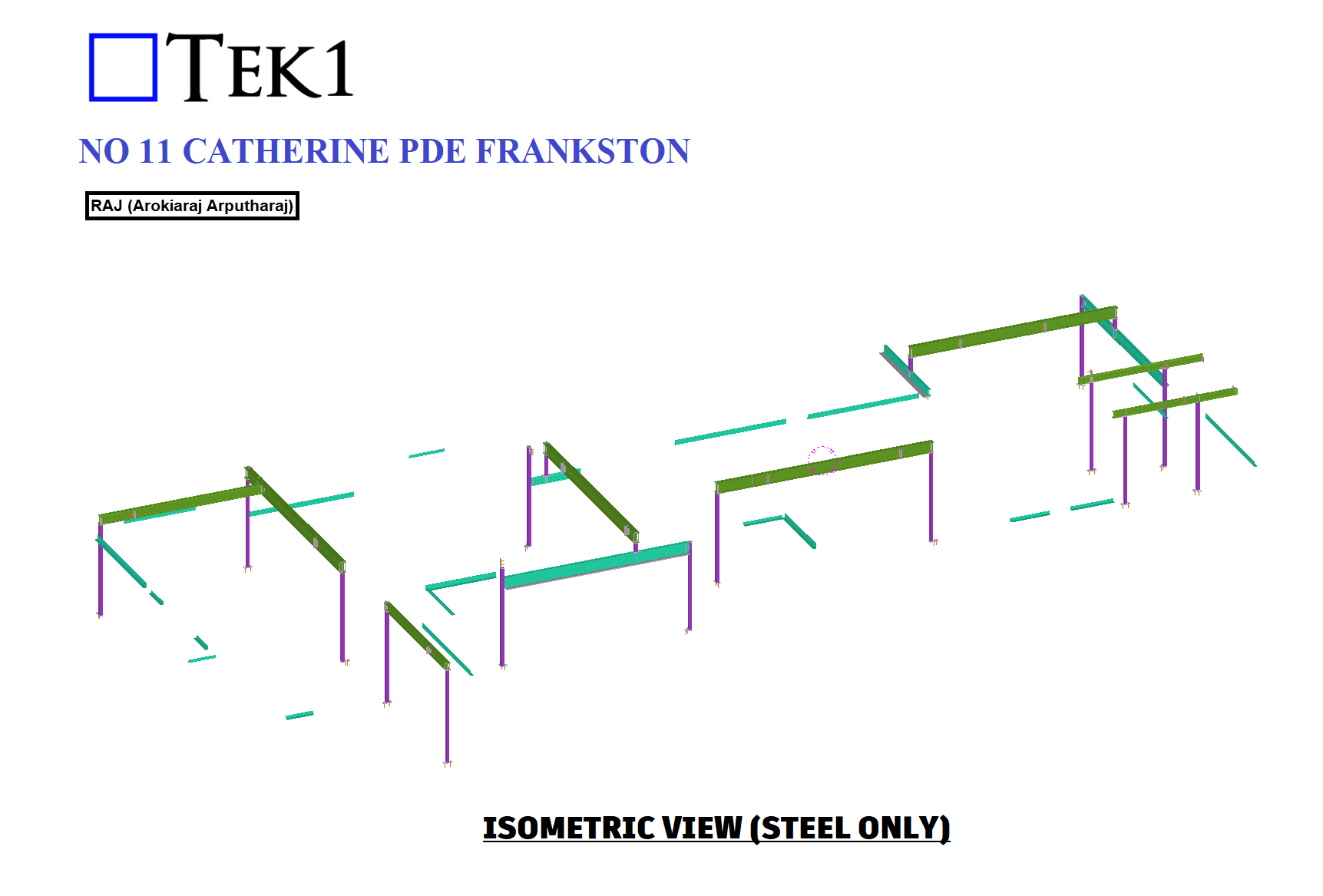
Shear connections play a crucial role in structural steelwork, ensuring the stability and strength of a framework. One common method is the extended shear plate connection, as seen in the R1 to J1 connection detail. However, this method introduces bolt eccentricity, which could impact the overall efficiency of the joint.
The Challenge
In the given design, the PFC (Parallel Flange Channel) shear connection is detailed using an extended shear plate. While this is a standard approach, it inherently results in increased eccentricity due to the offset load transfer through the bolts. This can lead to additional bending moments in the connection, requiring careful consideration in the design phase.
Possible Solution
A potential improvement is to introduce a cope in the PFC section and utilize a simple shear connection instead. This modification would:
Reduce bolt eccentricity
Simplify force transfer
Enhance structural performance
However, this approach was not accepted by the client due to fabrication ease considerations.
Key Learning for Junior Engineers
This case highlights a key engineering principle: design optimization vs. fabrication practicality. While structural efficiency is paramount, practical considerations such as ease of fabrication, cost, and site constraints often dictate final design choices.
If you would like me to assist with your project, please send an email to koshy@tek1.com.au with your project specifications. Kindly use ‘Raj’ as the subject header.
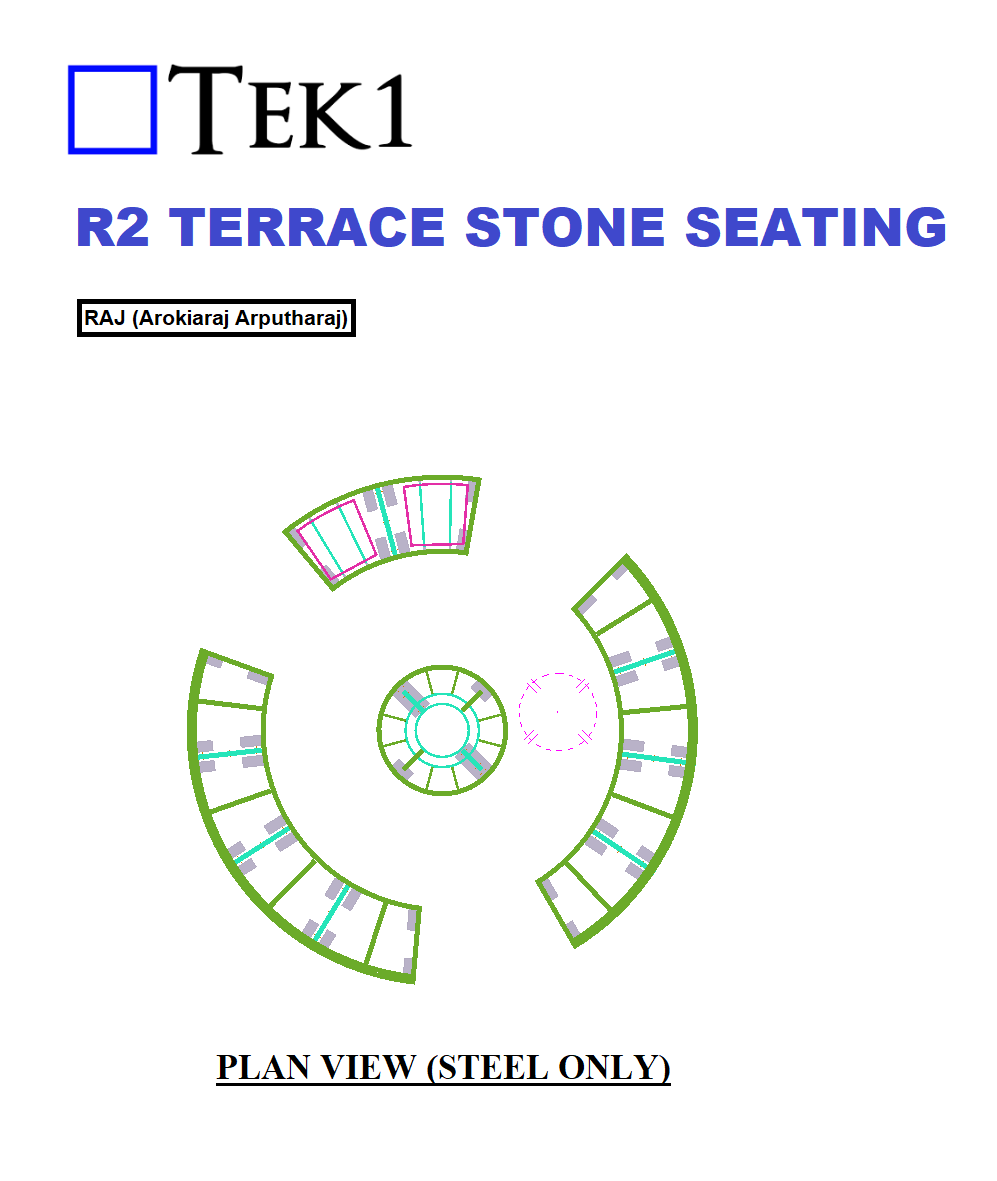
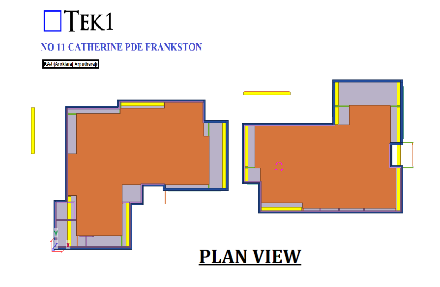
When performing detailed engineering for commercial staircases and balustrades, it’s essential to ensure that all aspects comply with AS 1428.1 and the relevant provisions from the Building Code of Australia (BCA), particularly those regarding accessibility and safety. Here’s a breakdown of the critical points you must address:
Compliance with AS 1428.1: 1. This standard outlines the minimum technical requirements for accessible buildings. Engineers must reference the BCA to align with safety and access provisions. AS 1428.1 directs engineers to follow BCA for detailed requirements related to stair and balustrade design, ensuring all safety standards are met, particularly for disabled access.
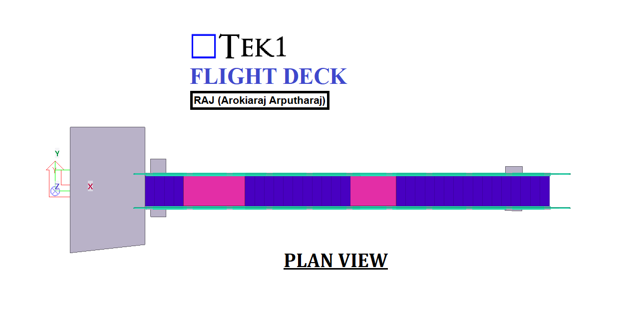
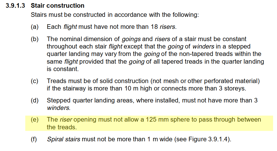
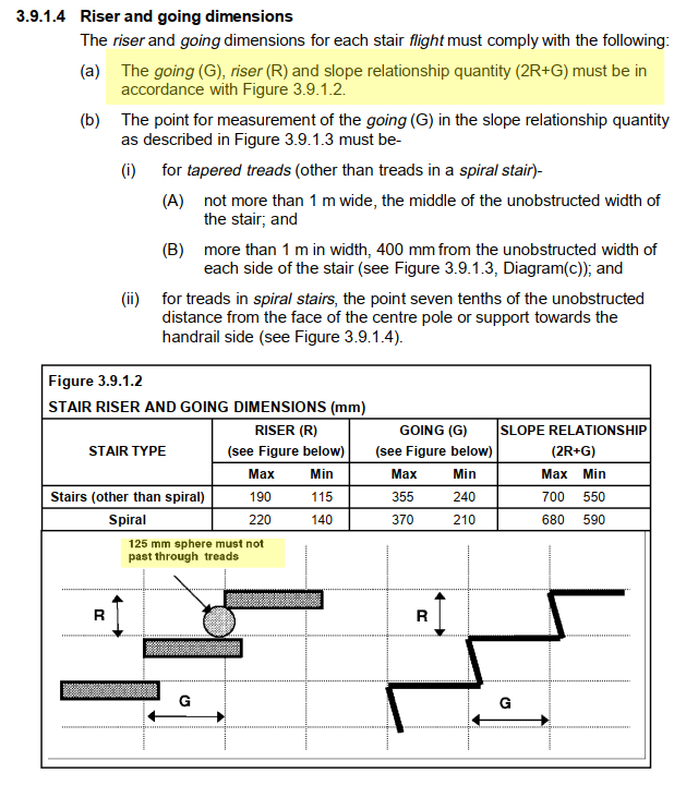
2. BCA 3.9.1.3 – Riser Opening Requirement: One of the key safety provisions under BCA 3.9.1.3 is ensuring that the riser openings on stairways are restricted. Specifically, the gap between treads must not allow a 125 mm sphere to pass through. This rule is vital for preventing accidents, such as children slipping through open risers. As a detailed engineer, you must ensure that this riser opening specification is incorporated into the technical drawings and calculations to meet safety compliance.
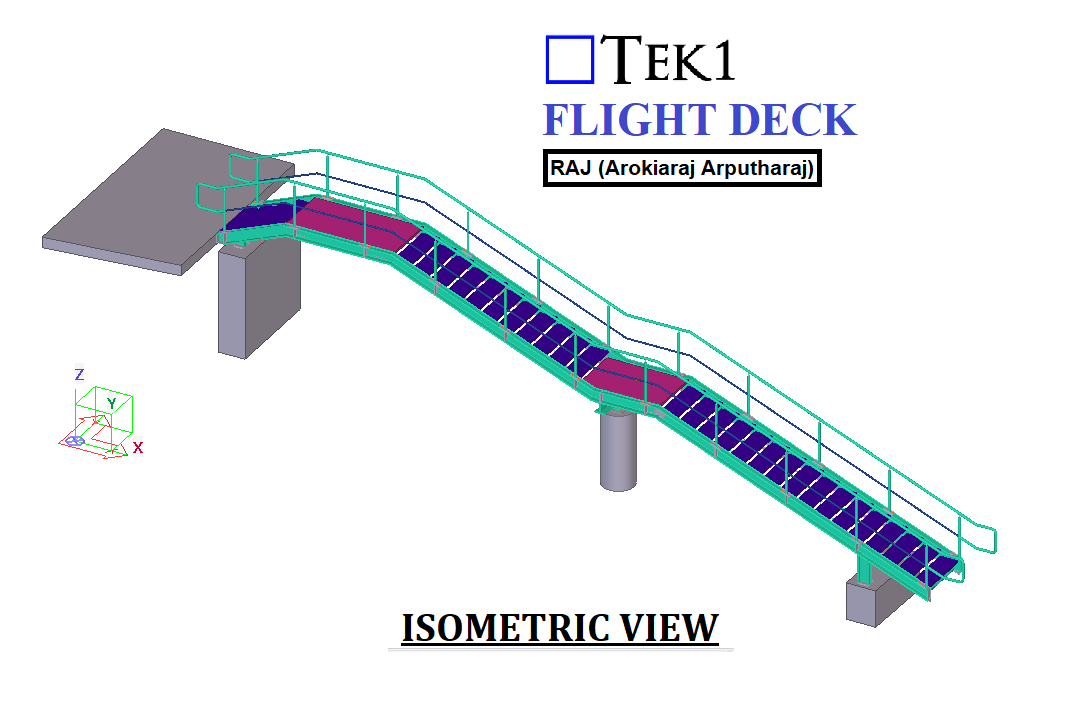
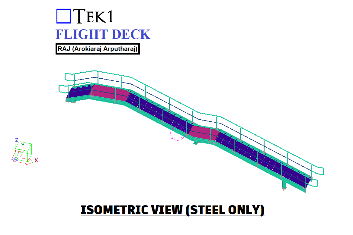
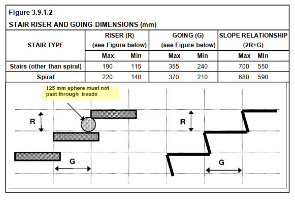
3. BCA 3.9.1.4 – Riser and Going Dimensions: Further, BCA 3.9.1.4 provides specific dimensional requirements for stair risers and goings, as illustrated in Figure 3.9.1.2. This figure shows the maximum and minimum values for risers (R) and goings (G), as well as the slope relationship (2R + G). Engineers must adhere to these dimensions for both spiral and non-spiral staircases to ensure that the stairs are not only safe but also ergonomically comfortable for users.
4. Critical Figures:
Riser (R): Must be within the maximum and minimum values—115 mm to 190 mm for standard stairs and 140 mm to 220 mm for spiral stairs.
Going (G): Must be within the maximum and minimum values—240 mm to 355 mm for standard stairs and 210 mm to 370 mm for spiral stairs.
Slope Relationship (2R + G): Must fall between 550 mm and 700 mm for standard stairs and 590 mm to 680 mm for spiral stairs. These values ensure that stairs provide both safety and comfort.
5. Ensuring Compliance: As part of the detailed engineering process, it’s your responsibility to ensure that all specifications, such as the 125 mm riser opening limit and the exact riser and going dimensions, are strictly followed in the drawings, materials, and construction processes. This involves validating these measurements on-site and ensuring they are reflected accurately in both the design and construction stages.
In conclusion, the detailed engineering process must ensure compliance with AS 1428.1 and the BCA, particularly regarding the requirement that the riser opening must not exceed 125 mm, as outlined in BCA 3.9.1.3. Additionally, the riser and going dimensions must conform to the standards specified in BCA 3.9.1.4. By adhering to these standards, you will ensure that commercial stairs and balustrades are safe, accessible, and compliant with Australian building regulations.