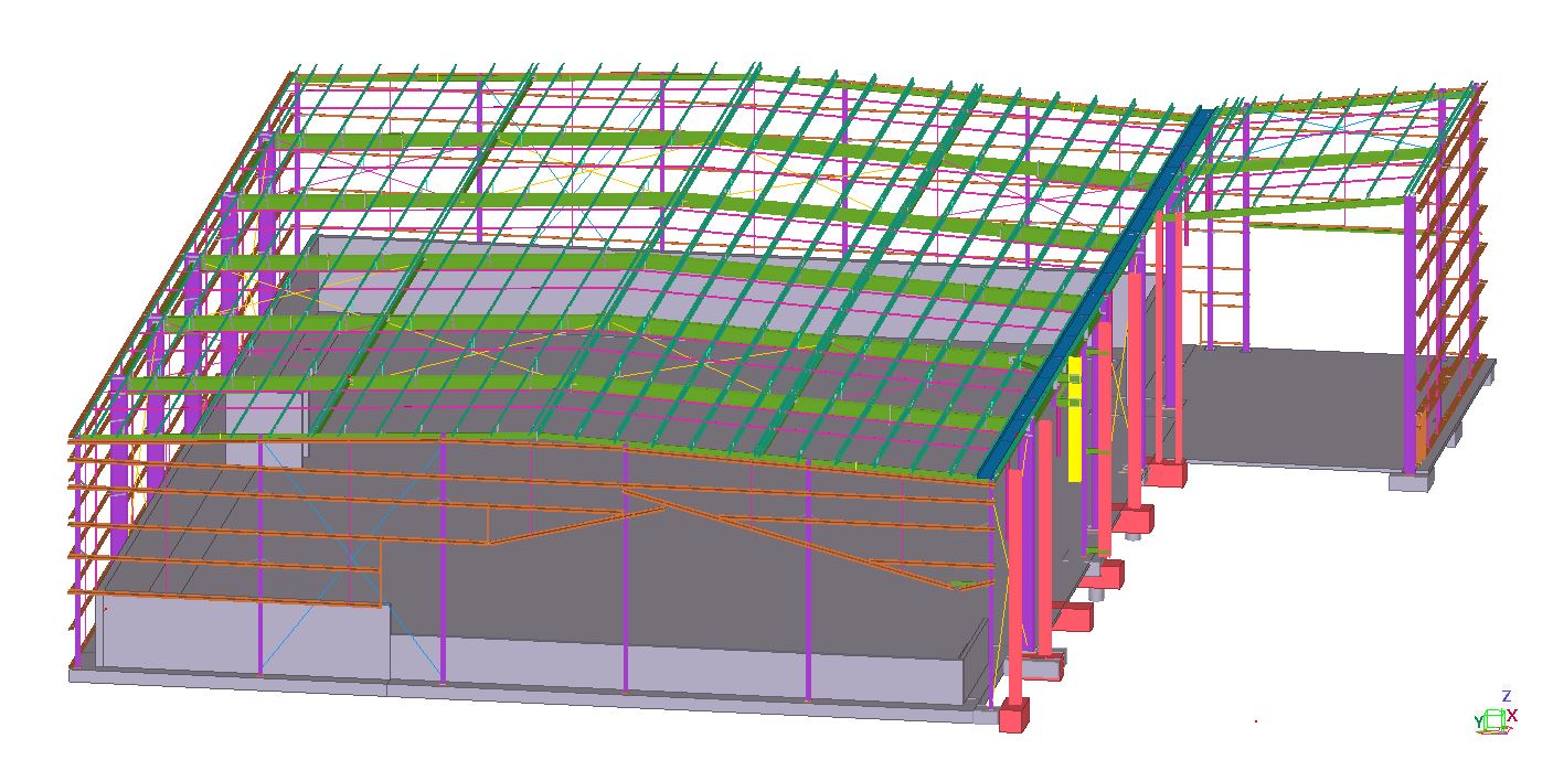
Location : 31 VALLEY FAIR DRIVE, NARRE WARREN
TEK1 Completed this multi-dwelling residential project with out any hitch.
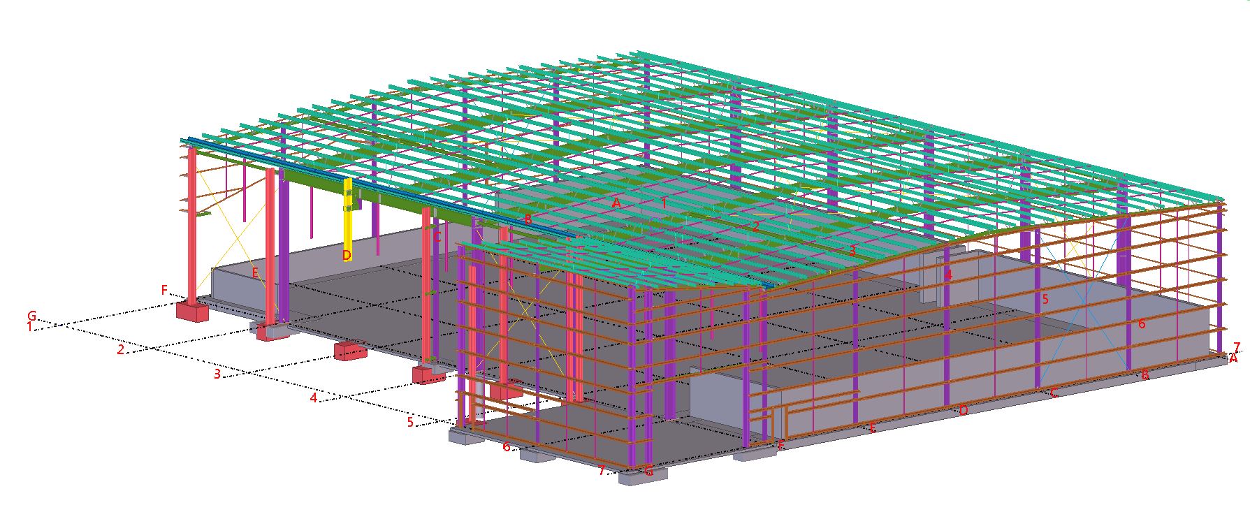
Location : 31 VALLEY FAIR DRIVE, NARRE WARREN
TEK1 Completed this multi-dwelling residential project with out any hitch.
Author: Ramakrishnan L
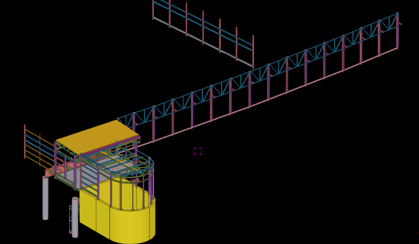
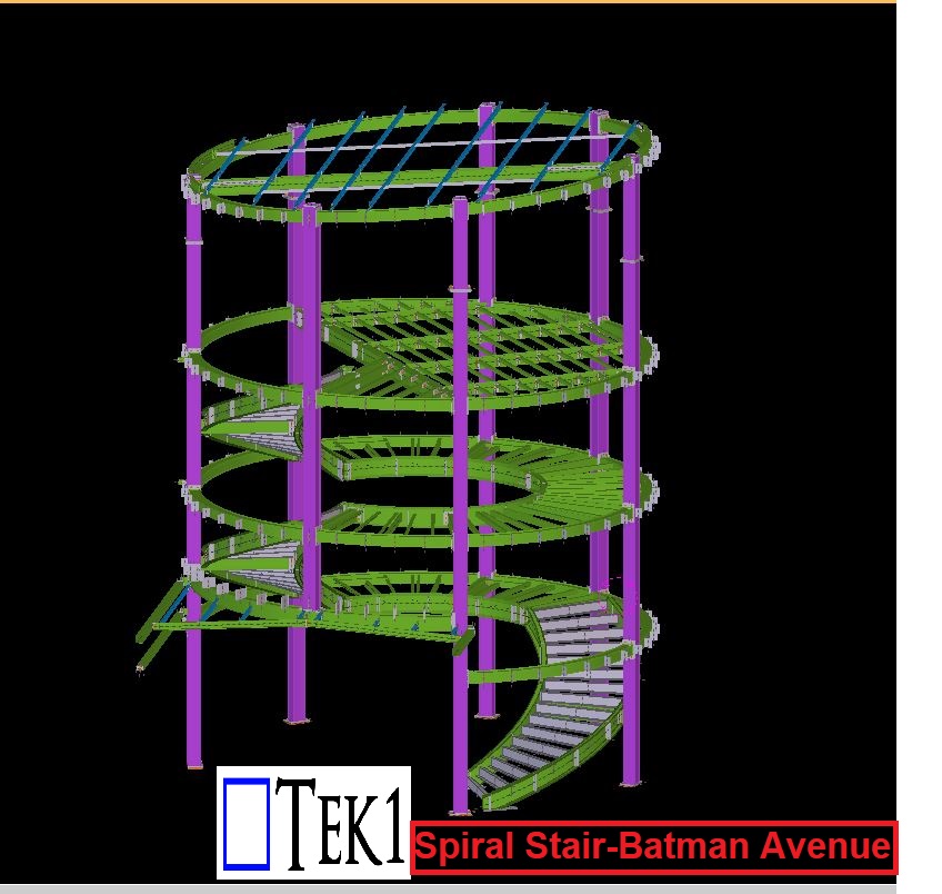
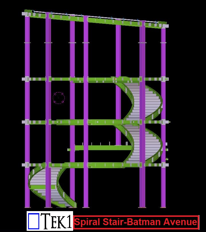
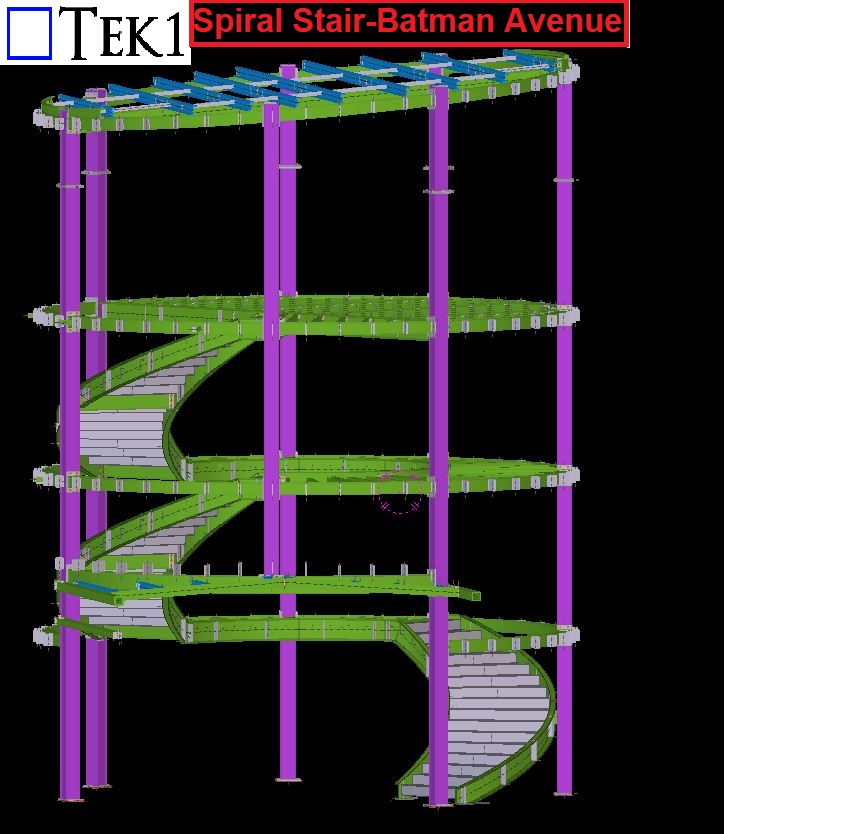
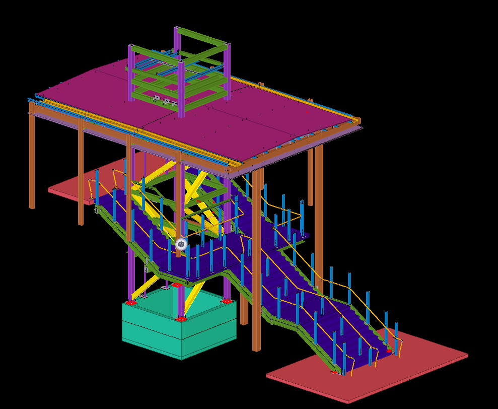
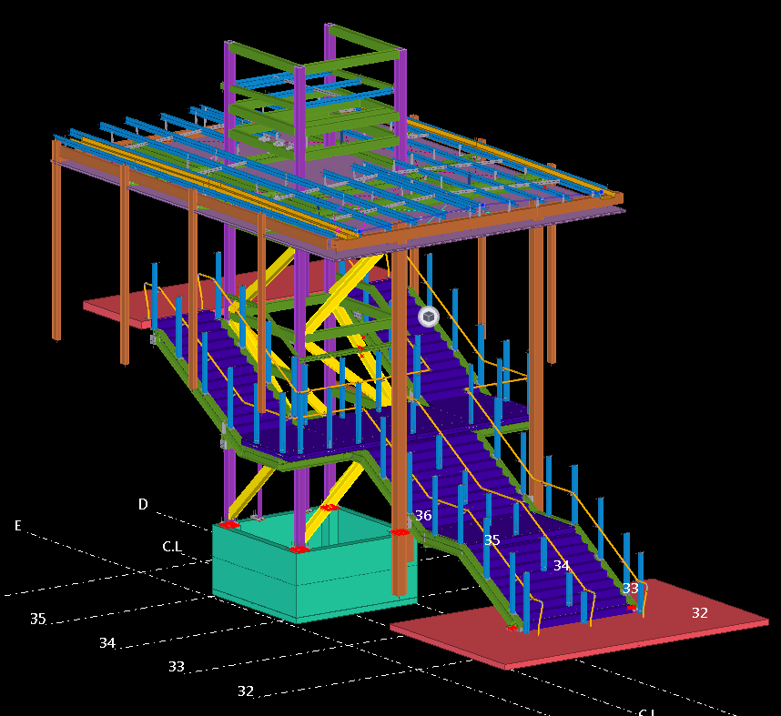
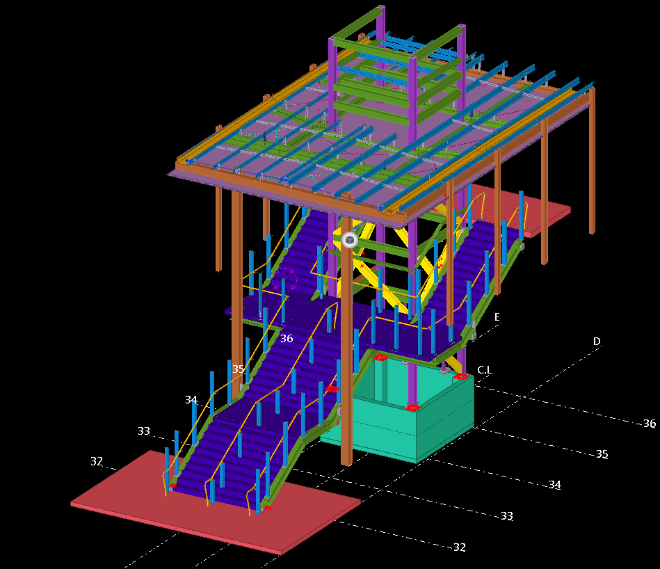
Tek1 has completed this rather complicated project “Circular Stair at Batman Avenue”.
The project was complex and demanded a very high level of detailing Knowledge. We have done wonderfully well in completing this project without a hitch.
If you want steel shop drawings for a project you are working on, please feel free to call Koshy on: (03) 9560 6397 / +61 3 9560 6397
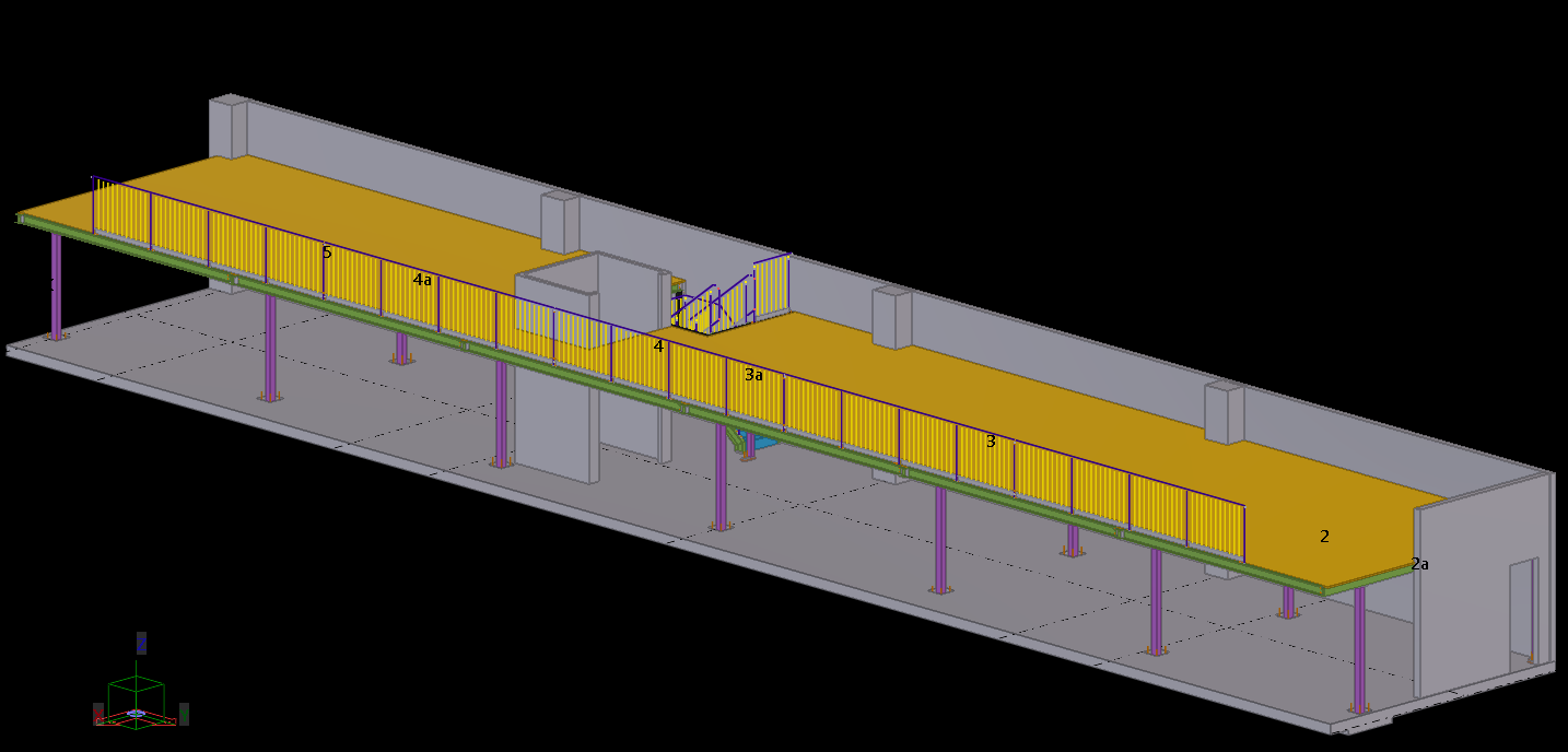
We have done a Lift & Staircase steel structure detailing on watergadens station located in Victoria.
TEK1 have done wonderfully well in completing this project without a hitch.
If you want steel shop drawings for a project you are working on, please feel free to call Koshy on (03) 9560 6397 / +61 3 9560 6397
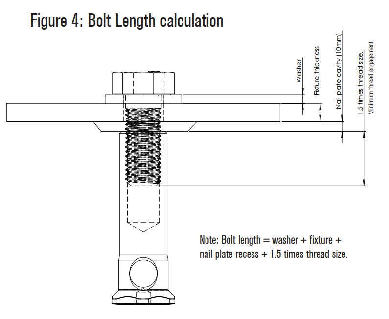
Main issue here is the entire length of bolt is decided by the Cut length the modeler provides.
If proper care is not taken, then there will be a site issue
Author: Pon Dhileepan
While working in a project called Bateman Bay, TEK1 came across a situation where PFC members are provided to support glazing. PFCs are laid flat, a 50mm U channel is run along the PFC which supports the glass. The below image is the cross section across the glazing and it elucidate the set up.

These PFCs are connected to columns by 10mm end plate & 16dia 8.8s bolts. The problem arose here as the bolt head of 8.8s bolt would clash with the glass. Refer below image for clarity.

Hence, TEK1 raised a query as to whether they can cut the glass where ever bolts clash or use CSK bolts. The structural engineer changed the 8.8s bolts to CSK bolts.
Another problem came as the PFC web is just 4mm whereas the CSK head is 8mm. The bolt head will still clashes with glass.

Then we proposed to weld an 8mm plate under the PFC and CSK drill is to be made together. The proposal is accepted. The below images show that the glazing runs without any hinderance.


TEK1 detected the issue earlier which saved cost in cutting the glass at site. Structural engineer often do not consider these kind of clashes and it is the duty of the modeler to find this out and make this to structural engineer’s knowledge.
Thanks for reading.
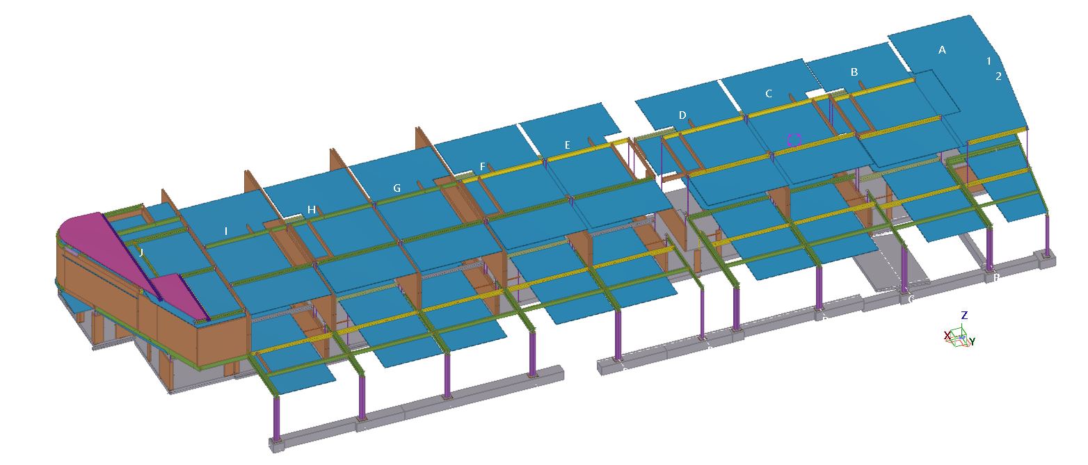
Does a detailer care about supporting the elements which are not available in the structural design, but it could affect the structure? You should care!
See the below incident for an example.

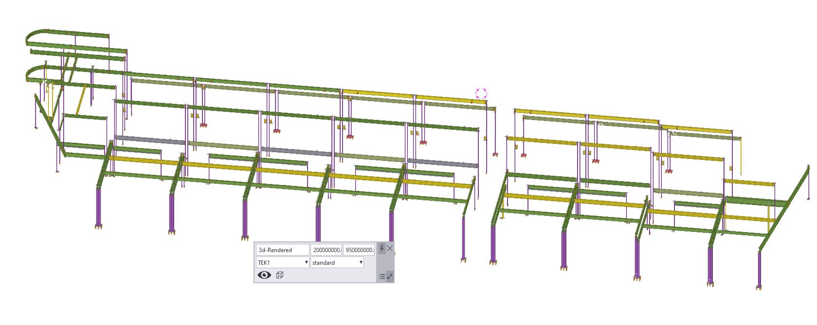
This structural plan has sections 1 & 2. Refer below snip for section views.

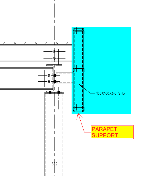
If you see the above snap, Section 2 has detail-A, which shows parapet wall support. But section-1 does not have it.
Is that means there is no support required?
Actually, there is also support required.
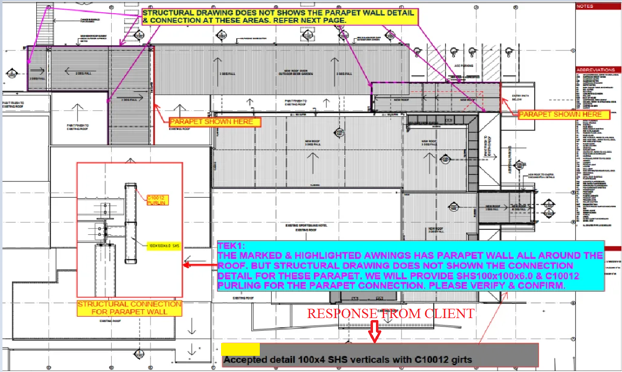
Refer below architect plan.
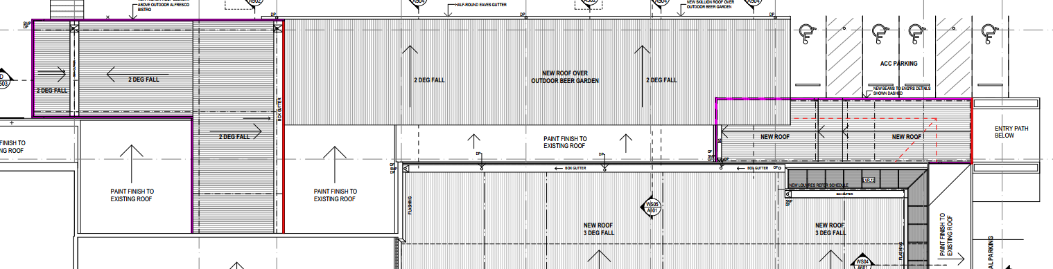
We have noticed that the parapet coming all around the roof (Highlighted in Pink Colour). So we raise RFI regarding this issue for taking it to their attention. Refer below snip.

The client realises the situation and approves providing parapet support members all around the roof. Refer below snip for the client’s response.
We always keep our client’s out of trouble from these types of issues.