Month: December 2019

  • DYNAMO: THE GAME CHANGER

    Automation is the process of making a task automatic, an essential requirement for all business processes to achieve accuracy in repetitive tasks, where humans or manual tasks are prone to error. One of the most powerful automation package of recent times in the construction industry is the Autodesk’s Dynamo. It is an open-source visual programming tool which works with Revit and other Autodesk products but could also be integrated with non-Autodesk programs using Standalone releases like Dynamo Studio, Dynamo Sandbox, and Project refinery.

    Unlike other Application Programming Interfaces which are used by well-grounded programmers, people with minimal coding knowledge can create custom scripts using the Dynamo to access the Revit interface. It runs on the background of Design script and Python. With Dynamo, the opportunities are endless and many time consuming tasks in various disciplines such as design, detailing, modeling, analysis, documentation can be automated.

    We use Dynamo to find potential solutions to problems we face day-to-day. One such problem was the unavailability of 3D grids in Revit. Moreover even when exporting a Revit model to CAD .dwg format, the grids failed to show up but they are available with Ifc exports. We developed a simple script to solve this issue using Dynamo.

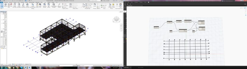
    The workflow between Revit and Dynamo is shown here.

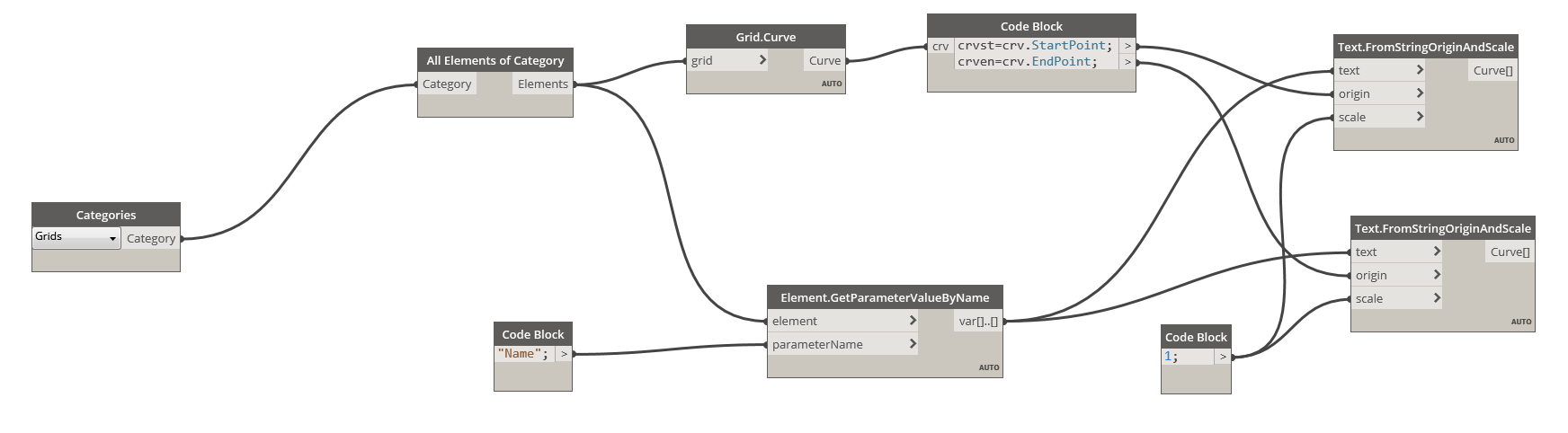
    The above snip shows the sequence of nodes in the dynamo workspace which were used to create Grids in 3D view.

    We found it quite interesting when we started digging to explore the capabilities of Dynamo to help us with our jobs. Learn more about Dynamo: https://dynamobim.org/

    If you have any questions or opinions about this post please do comment below.

    Written by Madhumitha Balaji

  • Can you spot the Problem#7

    When we place a beam, we need to consider several factors. The major one is to ensure that the beams do not clash with any of the aesthetical members such as the Cladding, Roof sheets, wall panel etc.
    In this figure.1 The engineer has provided a UC150*37 beam as 1B30 to support the external beam at perimeter and stud wall. If we fix the beam as per the architects specified location it will clash with the external wall finish (NASAHI WALL) by 40mm which is shown in Figure.2. We can not move this beam from its location because the supporting columns are hidden inside the walls for the aesthetic purpose by Architect.

    Engineer provides 150UC37 AS 1B30. Also, Architect prefers 50 thick NASAHI wall finish at the Perimeter.
    Model Snaps Shows the beam Clash with NASAHI wall.

    So we have no choice but to rather change the beam profile, This condition was explained to the Engineer and Architect by our detailer.
    The requirement was to change beam profile to be concealed and at the same time support the framework, thus was modified to PFC 200*75.

    As we change the beam profile the clash was eliminated

    Always be vigilant about these factors to avoid major mistakes.


  • HAVE YOU TRIED IN AUTO CAD #1: CUSTOM TOOL PALETTES

    Many of the time we use same commands and a set of procedure to work in drafting which consumes time we get used to it over time. For example: to insert a section tag we always need to use insert command and find the block and specify the scale and insert it eventually we need to consider scale of the view port which we are going to present the drawing.

    Instead of doing the same insertion every time we could customize a tool palette so that we could have a tools we use frequently.

    For example we need to label the members with its name in the layer “TAG” and color “GREEN”. We need not edit the property of the text every time. We can create a source file and save it on a common location (so that all the Auto CAD users can use the same file) and have the text in that file. And we could create a custom tab in the tool palette where we could just drag and drop and use it in all other files we work on. It will carry the general properties such as layer, color, line type and line type scale etc.. we could use the same for blocks, dimensions and all geometries as well.

    Notes:

    1. To view tool palette we could use command “TP”
    2. Create a source file in some network drive location with all the blocks so that it is easy for other users to fetch them.
    3. To create a new tool palette right click on the header then customize tool palette.
    4. In the customize window right click on the palettes list and create a new palette. We could do the same by just clicking on new palette option when we right click.
    5. Then we could just drag and drop the entries like blocks into the palette and now we are done with the loading part. We could use the same in any other drawings. It makes the work so easy and also helps by saving a lot of time.
  • Can you spot the problem – #6

    It’s one thing to model something on your computer. It is yet another thing to fabricate what’s drawn in 3d-land. Given the designs that we seen come through, I doubt very much whether the modern day architect has ever stepped foot in a workshop, or has fabricated anything in their lives.

    Consider the below example and see if  you can find any issues that should be blaring at you like a fire alarm.

    Pop quiz: What’s wrong with this?

    Something's not quite right.
    What’s wrong with this?


    What’s wrong here?


    Answer:

    • I think you might struggle to build it. I don’t think you can curve a PFC125 x 75 with a radius of 125 mm.
    • Can you think of an alternate solution?
    Ok, here's how we can fix the problem.
    Ok, here’s how we can fix the problem.


    Written by Gopal D.

  • .dwg based Take off with custom Plug ins

    Tek1 has developed .dwg based plugins which talk to Tekla to carry out take-off efficiently

    Take off is completed in .dwg based Cad systems very similar to modeling in Tekla. For BIM model the model is converted to Tekla

    Reports can be taken either from .dwg system or Tekla. Right now reports are being taken out of Tekla. Our next effort is to develop a plugin which will convert the .dwg model into an IFC model.

    If anyone is able to help us in this developing the plug int convert .dwg based model to an IFC model we will be very interested.

    Here is a sample file.

    Queens Cliff Estimation Model
    Tak off model