Month: March 2021

  • Custom Macro to Select Bolt Summary on Selected Assemblies-

    This blog is about the efficient use of using custom macro in Tekla Structures. Tedious or repetitive commands in a model could be time consuming. These repetitive commands can be automated by use of custom macro

    Understanding the bolt parts:

    In Tekla Structure the bolts can be created as single or in a group.
    Bolts are created with two parts joined together. We could consider as Primary Part (Part to bolt to) and Secondary Part (Part to be bolted).

    In Tekla Structures the bolts are released along with secondary parts

    ie. When Bolt Summary is taken, the bolt connected to secondary parts are extracted and displayed on the list.

    Recording the macro to extract the bolt summary:

    To record the macro. Click on the Application button.

    Then click on the access advance feature button and click record macro.

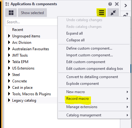
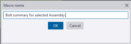
    You could choose either global or local to save the macros and define a name to the macro. Here we have named as Bolt summary for selected Assembly.

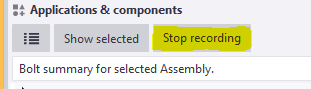
    Now the macro will start recoding.

    Follow the below steps to create the macro.

    Step 1: Press Ctrl+B for Reports List to appear.

    Step 2: Click on the required reports to be generated for the selected Assemblies.

    Step 3: Click Create from selected button.

    Step 4: Finally Stop the recording.

    Now Checking the custom macro created:

    1: Select an assembly for which bolt reports has to be taken.

    2: Double click on the custom macro to perform the task.

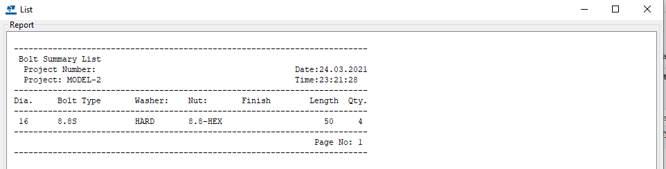
    The bolt summary for the Assembly is generated.

    Using the custom Macro we could define all the tedious and repetitive works in a custom macro and use to save time and man-work involved.

    Note:
    Incase the macro has been recorded with error. You could delete the custom macro created by right clicking the created macro and choose delete option.

    For creating API on “How to programmatically create bolt list reports from selected model objects”

    https://www.tek1.com.au/how-to-programmatically-create-bolt-list-reports-from-selected-model-objects-tekla-open-api

  • How to programmatically create bolt list reports from selected model objects (Tekla Open API)

    You want to programmatically create reports. Here’s how

    Reports can be generated fairly easily, manually. But how do you do it programmatically using the Tekla Open API?

    Please see below for a code sample:

    Programmatically Extracting Report Values

    • Now, if you want to generate the values programmatically, in memory, and then process them somehow into an excel output, consider the following code sample here.
    • If you want to programmatically select model objects, refer to the code pasted above.
    • The question: how to generate generate excel files given a particular hash table – this is not an issue pertaining to the Tekla Open API specifically though. I would use a library like CSV Helper to create a series of rows from the hash table.
  • Detailing Keys for Profile Spandrels, Shape columns in Precast concrete

    Steps involved in shop drawing created from Mould

    Process flow 

    1. Profile creation in 3d environments
      • We want to understanding the shapes , If we draw the 3d models clarified with the visuals, So we do profiles in 3d
      • 3d model views are easy to understand the Profiles & more clarity
    2. Analyze the 3d/isometric views & clarity dimensional sections in shop drawings
      • After finishing the model cross check the Profile clash, component clash, Perpendicular views & its properties.
    3. Mould creation
      • created the mould for all the shapes.
      • Get advice from the factory those who are making the mould for this shape of panels in precast concrete.
      • Finalized the mould drawings.
    4. Shop Drawing details for understanding
      • Grout tube setouts
      • Profile setouts
      • Reinforcement clarity section & Isometric views

    Shapes of the Precast in 3d Model


    Isometric views shown in shop drawing for clear understanding


    •  

    Final output of the building is


  • Information Gathering for precast detailing from consultant drawings

    Precast detailing is the process of create detailed drawings of each component in precast. The precast drawing is responsible for extract structural design calculations and Architectural innovative.

    Precast detailer utilises Architectural, structural and services drawings to gain a working knowledge of the overall design intent of the building. precast detailers will draw the precast detailed drawing with refer Architectural, structural and services with some technical standard to achievable manufacturing, transport ability and Build ability

    So detailer should aware about the information Gathering from consultant drawings to precast detailing

    Here we are going to explaining about the thing needed to focus on ARCH GA PLAN for precast detailing


    ♦ Viewing direction:

      1. Viewing direction should be from INSIDE of building (i.e. should not view from Visible side of building) because panel FAR FACE should be at TABLE FACE to get GOOD TABLE finish. Based on Finish purpose and mould similarity we can also view from outside of building
      2. But we need to consider some conditions here
        • Up stand/corbel /crank profiles are quiet difficult to cast in far face so viewing direction need to place based on to match those profile comes at NEAR FACE
      3. Architectural pattern(e.g. Groove, Reckli, Brick snaps etc.) always try to place FAR FACE,

    Note: Study all levels before provide viewing direction of panel at bottom level because once direction provided it should not be changed for that elevation until end of that panel.


    ♦ Finish:

      • NF Finish – Trowel, Semi Trowel, Float, Polished, Broom or Custom
      • FF Finish – Table, Good Table, Reckli, Polished, Retarder, Patterned
    1. Mostly we use Trowel and Float finish, Good table
    2. Other type of finish used only when clients special requirement
    3. Study GA PLAN or WALLS drawings and provide trowel finish at visible area.
    4. Refer Arch Elevation for additional finishes and pattern requirements, if any things specified in handover

    ♦ Inside and Outside:

      1. Study GA plan based on general arrangement on plan like bedroom , balcony ,corridor living room , study room , Lift area , stair area etc.
      2. Provide visible places/outside of building as Outside and Non visible places/ inside of building as Inside.
      3. If given OUTSIDE, factory will take additional care for finish.

    ♦ Weather proofing:

    1. Weather Proofing for a panel provided based on panel locate at below condition
      • Inside / Outside – weathering require
      • Inside / Inside – No weathering require
      • Outside / Outside – No weathering require
    2. By considering inside and outside location of panel and arrangement on GA plan provide weathering and return values for panel
    3. Provide weathering at window sill level and lintel level.
    4. Provide weathering at spandrels if bottom area covered with window

    Mainly weather proofing is used to terminate fluid flow into the building


    ♦ Exposed edge:

      1. Study GA plan and provide Exposed edge at visible edge of panels like outside edge of panel, door & window frame openings and top of panel which are visible
      2. Service openings on panel also need to provide exposed edges(Not require for small penetrations)

    ♦ Horizontal Groove requirement :

      1. For spin-up panels present at visible area of building we need to provide HORIZONTAL GROOVE to match adjacent drop-in panels breakup or some case good visibility purpose.
      2. We need to raise RFI to confirm those groove requirement to follow for that entire project
      3. Edge Groove or Return Groove requires only when FF groove continues and also comes at NF (NF visibility at outside). In these cases NF groove usage need to confirm with Builder.

    Study GA plan and provide as per requirement of that panel location.


    ♦ FSL RL detail:

      1. In some projects they clearly specify FSL- FINISH SLAB LEVEL RL in GA plan.

    Take that value from GA plan and use it while detailing Overflow, & Lift Door opening.


    ♦ GT breather face:

      1. Breather face provided based on slab access- Should not provide no slab access face
      2. Perpendicular walls/ panels clashes – provide GT extension if clashes with it or else change face if both sides are trowel finish
      3. NF/FF Finish of panel-avoid breather on exposed face(visible face)
      4. Breather must not provide at arch pattern face

    Its Easy to manufacture breather face locate at FF/ TABLE FACE


    ♦ Prop face :

      1. Recess for prop provide based on finish for that we need to refer GA plan
      2. Prop face provided based on slab access- Should not provide no slab access face
      3. Perpendicular walls/ panels clashes – change or move prop location if not provide suitable prop type
      4. Check with structural /Arch conc setout to find prop not locate at slab penetration location
      5. Check with PT drawings to find prop not locate at PT stress pan

    Its Easy manufacture PROP face locate at FF/ TABLE FACE


    ♦ Door and window openings:

      1. If No Door/ window schedules provide for that project we need to refer location and size of door / window form GA plan and must confirm with Builder.
      2. For height, manually calculate height from CAD elevation file and ask TBC with Builder.

    ♦ For extent of arch pattern refer GA plan wherever applicable

    Note: – In next session we will focus on Information Gathering from ARCH CONC SETOUT PLAN to precast detailing.it will be post ASAP

    Thanks to Ben for supporting me in blogging login & posting, special thanks to Koshy & Venkat for supporting on this document & regulatory me 

  • Metal Edges in Bubbledeck Slab

          Metal edge is the 2mm to 3mm thick Galvanized Sheet which are mainly placed in the building edges of the Slab to stop the overflow of concrete while pouring on the Bubble deck Slab arrangements.

         Metal edges are fixed in the factory and not on site; it will be fixed while pouring the minimum thickness concrete slab biscuit. So the metal edge are comes under the category of castin items in Bubbledeck Slab.

    Application of Metal edges:

    • Bubbledeck Slab Edges  that connects to Post fixed precast wall (Post fix wall will be erected once after the bubbledeck Slab are installed and Poured).
    • Slab edges which are free from the wall. Especially near to balustrade Areas
    • Duct and services void in slab which is present  inside the Building
    • Soffiit Step / Slab fall in slab

    Advantages :

    • Fine Finish of slab edge (Visible edges) can be obtained
    • No side shuttering is needed
    • Site work can be reduce due to fixing in factory long with min concrete Slab pouring

    Disadvantages:

    • The cost of Metal edge sheet is high compare to timber because of galvanized
    • The metal edge to be order 10 days prior from casting on minimum concrete because of sheet galvanizing

    Handling Problem:

      The Metal edge is not safe to use 450mm and above height. This may lead to bend and damage of metal edge sheet during the time of Bubbledeck Biscuit Transportation.

      The Metal edge can’t be fixed on the round edge profiles of slab and applicable only for square edge Profile.

  • Precast Bubbledeck Slab Casting Process

    STEP 1: TABLE PREPARATION

    STEP 2: CONCRETE POURING IN THE TABLE

    STEP 3: REINFORCEMENT SETOUT LIFITNG USING IN HOUSE LIFTERS

    STEP 4: REINFORCEMENT SETUP PLACEMENT IN TABLE WITH MIN HEIGHT CONCRETE ON IT

    STEP 5: VIBRATOR PRESSURE ON TOP OF MESH TO SUIT BOTTOM REO WITH CONCRETE

    STEP 6: CURING TIME FOR CONCRETE SETTING WITH REINFORCEMENT

    STEP 7: LIFTING THE PANEL FROM THE TABLE

    STEP 8: PANEL STORED IN YARD AFTER CASTING COMPLETED

  • STEEL MODELER ATTENTION – DEALING WITH CAMBER

    TEK1 worked in a railway foot over bridge with 2 lifts, 2 ramps, 2 stairs connecting platform and overpass, a canopy and 7 platform stairs. The main challenge is the over pass. As per design, the steel truss after erection must be cambered to different millimeters at different intervals. There were two terms “Residual camber” and “Reference Profile” in the structural drawing. Many do not that what these mean. Any misunderstanding about these terms would result in redoing the entire overpass. But TEK1 had good understanding of these terms and avoided heavy rework.

    This blog is to educate the modelers regarding residual camber and reference profile. Kindly refer the camber diagram below.


    The residual camber at the south end is 67mm and reference profile at the same end is 62mm. Residual camber is the camber value which must be given in the steel assembly drawings which the steel detailer supply. Whereas reference profile is the camber value which the structure attains after applying all the dead loads. Here the dead loads are concrete load and self weight of the steel.

    Hope this helps you. Thanks for reading.
    Ramakrishnan.L
    TEK1.