Month: April 2021

  • How to Get Bolt Information From A Tekla Part (Tekla Open API)

    Given a Tekla Part (regardless of how it was obtained, we want to obtain the bolt information. We can do so as follows (see the hello world example):

  • Tekla Tutorials For Beginners

    Core Competencies T1 & T2 – colored

    Tekla Skills

    See Video Tutorails Below: (I prefer Vimeo because you don’t have to deal with insufferable ads)

    Youtube Playlist.

    1. Tekla UI: Youtube: (English) (Tamil) / Vimeo: (English) (Tamil)
    2. Columns: YouTube : (English) (Tamil) / Vimeo : (English) (Tamil)
    3. Beams Part 1 : Youtube (English) (Tamil) / Vimeo: (English) (Tamil)
    4. Beams Part 2 : Youtube (English) (Tamil) / Vimeo: (English) (Tamil)
    5. Plate : Youtube (English) (Tamil) / Vimeo: (English) (Tamil)
    6. Bolt : Youtube (English) (Tamil) / Vimeo: (English) (Tamil)
    7. Weld : Youtube (English) (Tamil) / Vimeo: (English) (Tamil)
    8. Concrete member
    9. Column :Youtube (English) (Tamil) /Vimeo: (English) (Tamil)
    10. Beams :
    11. Slab :Vimeo:(Tamil)
    12. Panel :Vimeo:(Tamil)
    13. Footing :
    14. Edit Ribbon :
    15. Grids : YouTube : (English) (Tamil) / Vimeo : (English) (Tamil)
    16. Cut/Fit/Split/Combine :
    17. Chamfer :
    18. Compare members :
    19. Measure :
    20. Points :
    21. Construction object :
    22. View Ribbon
    23. New View/ View list/ Saving view :
    24. Work Area/ Clip plane :
    25. Work plane :
    26. Representation :
    27. View properties :
    28. Screenshot/ Fly/ Rendering :

    Sample Project files :

    Solution for the project files :

    Please find Vimeo link of tutorial videos : Tekla Tutorial For Beginners


    Other Skills:

    • Improve your english: If you’re English skills are weak, then you need to improve it. Don’t “practice your mistakes”. The easiest way to improve is by shadowing. Spend 1 hours a day for a few months – your career will massively benefit as a result of this. Why should I bother learning English? (1) To avoid miscommunication, (2) Clients HATE bad grammar, (3) you will be rewarded financially in your career (clients will prefer you).
    • Learn how to dimension properly.


    The following are tutorials done by Koshy:

    1. Tekla Introduction
  • Information Gathering for precast detailing from STRUCTURAL PLAN

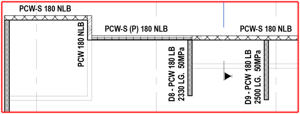
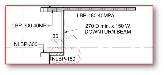
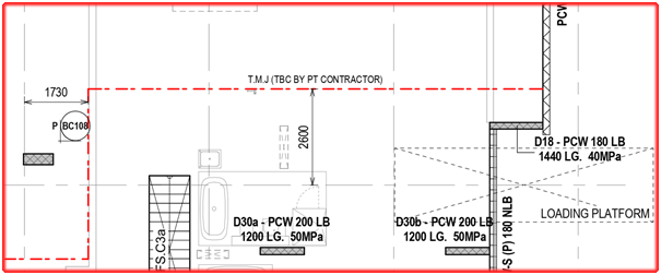
    Here we are going to explaining about the thing needed to focus on STRUCTURAL PLAN for precast detailing

    • Width /Thickness of panel:
      1. Panel width and thickness should satisfy min structural requirement because structural engineer worked with that structural requirement of panel to provide building strength and stability. If we provide less than structural thickness and width then we cannot achieve strength and stability.
      2. Greater than structural thickness will come because of groove/pattern but it should not be less than structural thickness. (If groove/pattern returns on panel edge, raise RFI to confirm width extension). 
    • Mesh detail:
      1. Schedules created and specified its required type for each and every panel. Legend type need to take from plan and refer it with schedule.
      2. Refer reinforcement schedule if they provided or else refer handover reinforcement schedule. (if schedule missing please discuss with Builder)
    • Grade of panel:
      1. Mostly plans shows direct grade value of panels
      2. Schedules created and specified its required grade for each and every panel. Legend type need to take from plan and refer it with schedule.
      3. For spandrels, they will not provide any values. In that case use 40MPa grade.(UNO)
      4. For columns, shear walls and cores grade to be referred from its respective schedule.
    Fig: Structural plan showing Grade value
    • Load bearing/ Non- Bearing of panel:
      1. These are decided by engineers and specify on structural plans
      2. Generally precast panels are
        • Load bearing panel– Separate hatch will show or legend will show as LBP
        • Non-load bearing panel– Separate hatch will show or legend will show as NLBP
        • Partially load bearing panel-If they provided some distances only as LBP means then that remaining part of panel is non-load bearing. So that panel will be partially load bearing.
      3. In some special case if structural engineer instructs to refer any drawings, we must refer that drawing for NLBP/LBP region
      4. As default spandrels are NLBP but don’t show it on panels.   
    Fig: Structural plan showing LBP and NLBP
    • Slab thickness:
      1. Thickness of slab provided in this plan
      2. Extent of Folding on slab profile values also given in this plan
      3. For critical profile draw slab profile in 1:1 ratio
      4. If no step ups/down slab thickness provided, in that case use minimum slab thickness value along with step value. (If hidden line step occurs on under-side of slab and if continuous line step occurs on upper side) – Those details are clearly visible only on PDF.
      5. Stair landing slab thickness usually not given in stru plan, we need to refer that from relevant stru stair drawing
      6. Most of cases nominal slab thickness for particular level will be noted in its title sheet. So PDF reference is must.
      7. If Sectional details provided, it must be refer for additional information
    Fig: Structural plan showing Slab Thickness and Slab Folding
    • Temporary movement joint/construction joint:
      1. A line with legend for temporary movement/ construction joint shown in structural drawings
      2. We need to consider this while providing panel breakup because slab pouring sequence may change and it will affect panel
      3. In case no other way to provide breakup at those location, we need to detail our panel profile based on joint location
      4. It must be consider while providing props location/ GT breather face.
      5. Temp connection is not needed when precast seat on different pour.
    Fig: Structural plan showing Temporary movement line
    • Extra reo details :
      1. Sometimes structural engineer requires additional reo specification for certain panels
        • In this case they provide separate elevation with drawing number, we have to go through that elevation and provide reo for our panel
        • In plan itself they provided excess reo detail
        • Some indication will provide for additional reo detail and that relevant detail will be provided on title sheet.
    Fig: Structural Elevation showing for Panel Types
    Fig: Structural Wall Schedule for Precast Details
    • In-situ connection detail:
      • Precast that are connecting with in-situ will be highlighted in handover & structural drawings.(it differs only on some special cases)
      •  Separate drawings or sectional detail provided for connection between insitu and precast. We need to study and collect connection information from it.
      • If Precast connects with in-situ and connection details not provided means we have to raise TBC for it. 
      • If NLBP connects with in-situ we must confirm with Builder
    Fig: In-situ connection with precast panels
    • Slab profile type:
      •  Slab profiles are determined and highlighted in special legend.
      • Those determined profiles are classified as different types and provide it in a separate drawing
      • By study those type and legends sometimes we need take slab profile cut values and folding values for slab profile  
    Fig: Structural plan showing Special legend for slab profiles


  • Types of Brace (Prop) Plan

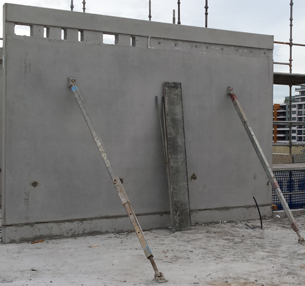
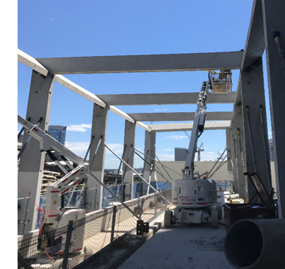
    Brace are used for temporarily support precast concrete elements until the permanent fixing are made.
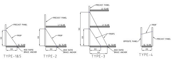
    1. Single storey (Drop-in) panel propping
    2. Double storey (Spin-up) panel propping
    3. Panel higher than double storey propping
    4. Panel to panel propping
    5. Edge Propping
    6. Spandrels propping

    1. Single storey panel propping:
          Single story panel are normally used 2 props a panel. Some times more than 2 props are used based on panel design.

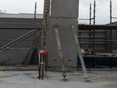
    2. Double storey panel propping:
         
          Double story panel are normally 2 props placed 200mm below the underside of slab. Some times more than 2 props are used based on panel design.


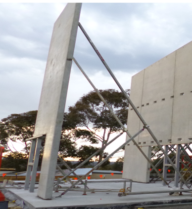
    3. Panel higher than double storey panel propping:
           This type of panel needs two level of propping. Two props on the below level and two props on the above level. If there is a slab in above level the propping system will pass through the below level slab by providing a pocket on the slab

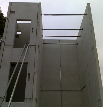
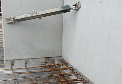
    4. Panel to panel propping:
       
    Provide ferrule in the opposite panel Or Adjacent panel for propping. Especially this kind of propping system are applicable for lift and stair core area, where there will be no slab to support the prop.

    5. Edge Propping:

        These types of propping are used for column and some panel having cantilever. Provide ferrule in the edge of the panel.

    6. Spandrels propping:
       
    These types of propping are used for spandrels. Provide ferrule at the top of panel. Where the ferrule will be connected with the member which hold the propping system.

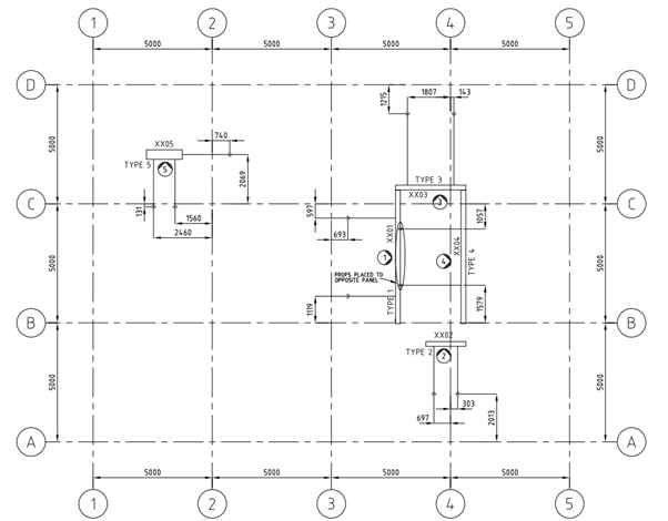
    Model brace plan drawing:


  • Advanced Steel Tool – Convert AutoCAD lines to Advanced Steel Beams

    Why bother with this tool?

    Because drawing Advanced Steel Beams is very cumbersome. If you have a CSV file you can draw AutoCAD lines and conver them with a fairly simple macro. Everything is open sourced, so you can fork or submit a PR if you require.

    Here is a video demonstrating this:

    If you want to download it, please see check out this link.

    Source code is available here.

    I had written a more advanced user interface for AutoCAD. Perhaps I will incorpoate that into Advance Steel when I get the time. Porting it is a little tricky/complicated it.

  • Information Gathering for precast detailing from Arch Conc Setout Plan

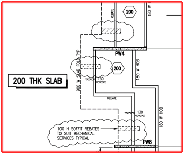
    Here we are going to explaining about the thing needed to focus on ARCH CONC SETOUT PLAN for precast detailing

    • Panel Set-out & width:
      1. Mostly we prefer to use Precast Set-out from Conc set-out but before proceed with this drawing , we need to raise RFI to Builder to confirm this Drawing need to follow for this entire project.
      2. If panel set-out, dimensions, openings annotate on conc set-out means use that value.
      3. Please look over for special indication that denotes architectural patterns

    • Slab RL:
      1. SSL value is provided on conc plan with respect to top profile of slab.
      2. Slab step downs/ step up profiles are specified in this plan by its RL values and some special legends

    • Slab thickness:
      1. Some architects, they clearly specify their slab thickness in concrete setout itself but we need to confirm that slab thickness with structural drawings.

    • Parapet/spandrels/window &Door RL:
      1. In most of the cases spandrels top RL specify in this plan
      2. In some case, for parapet wall (top of wall)RL should take from this plan
      3. In some case ,sill RL and header RL for window will be given in this plan
      4. In some case ,sill RL and header RL for door will be given in this plan

    • Overflow location :
      1. Overflow need to provide at balcony/terrace areas
      2. Location and size of those overflow can be taken from precast panels concrete setout
      3. If overflow location not provided we need to raise TBC for overflow location.

    • Slab / wall peno location:
      1. Penetrations are require to provide for varies purposes
        • Service penetrations at slab
        • Service penetrations at wall
      2. These penetration locations and sizes are need to take from this plan as well as elevation.

    • Profile Type:
      1. Slab profiles are determined and highlighted in special legend.
      2. Those determined profiles are classified as different types and provide it in a separate drawing
      3. By study those type and legends, sometimes we need take slab step ups/downs values and nominal folding values for slab profile.

    • Alimak /loading platforms/ Hoist locations:
      1. Those void locations are helpful in providing breakups and panel erection type
      2. Alimak are type of material transport car, used to transport building materials to all levels. Where alimak is present we can’t erect precast.
      3. If panel locate at alimak/loading platform /hoist, it will affect construction materials transportation.
      4. So some modification on construction process will require at those locations ,precast may also be changed to in-situ and some cases it can be as post –fixing panels
      5. Breakups also need to consider while doing marking plan.

    • Pattern Groove Set-out:
      1. Pattern groove set out – some rare case only, architect show pattern groove set out in conc plan. (Mainly refer architect elevation)
      2. If they provided it will more helpful in providing panel breakup, based on groove only we need to provide breakup for panels in continues elevation.

    • Ramp profile:
      • Ramp slab: Data’s provided for ramp in two ways
        1. Ramp profile increasing ratio (percentage) will provide between two points, length will be measured between those two points
        2. Starting point and ending point RL’s will provide between two points, length will be measured between those two points
        3. If additional ramp sections provided, then we also need to consider it.

                                 Above data’s will provide in conc setout plan. We need to take those data and work it out for exact ramp profile of slab


    • Slab boundary line:
      1. For slab boundary line, we need to refer slab extent in conc plan

  • RFI for additional support members required

    Does a detailer care about supporting the elements which are not available in the structural design, but it could affect the structure? You should care!

    See the below incident for an example.

    STRUCTURAL PLAN

    This structural plan has sections 1 & 2. Refer below snip for section views.

    STRUCTURAL SECTION VIEWS
    DETAIL-A WITH PARAPET SUPPORT

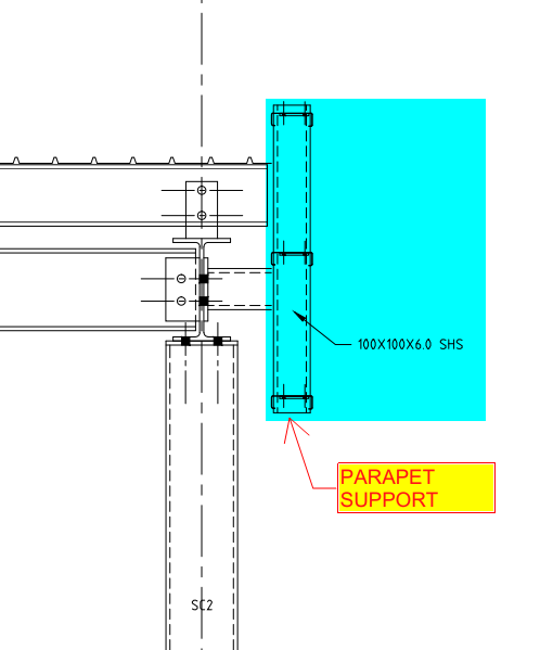
    If you see the above snap, Section 2 has detail-A, which shows parapet wall support. But section-1 does not have it.

    Is that means there is no support required?

    Actually, there is also support required.

    Refer below architect plan.


    ARCHITECTURAL PLAN

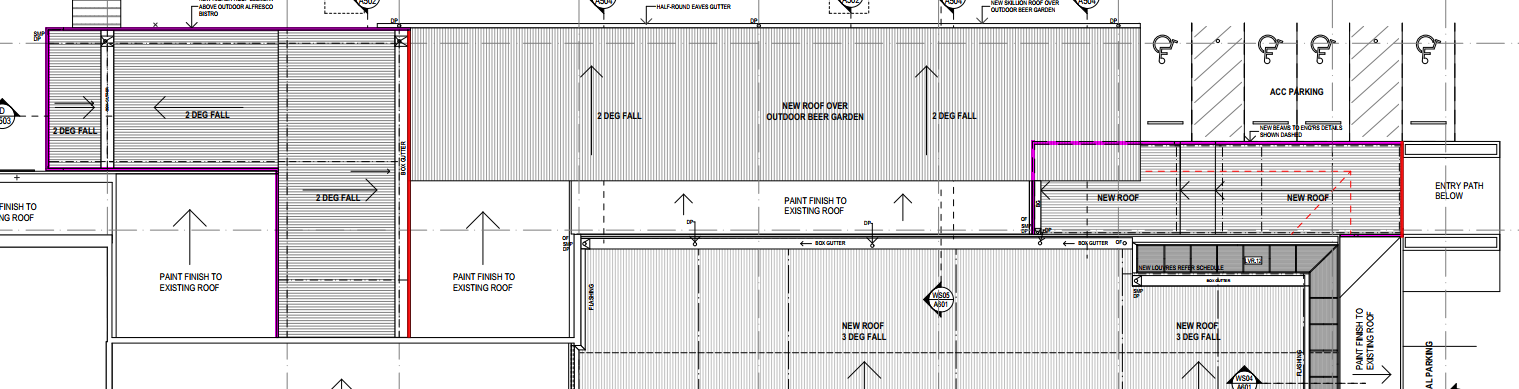
    We have noticed that the parapet coming all around the roof (Highlighted in Pink Colour). So we raise RFI regarding this issue for taking it to their attention. Refer below snip.

    RFI RAISED BY TEK1 REGARDING PARAPET SUPPORT

    The client realises the situation and approves providing parapet support members all around the roof. Refer below snip for the client’s response.

    RESPONSE FROM THE CLIENT

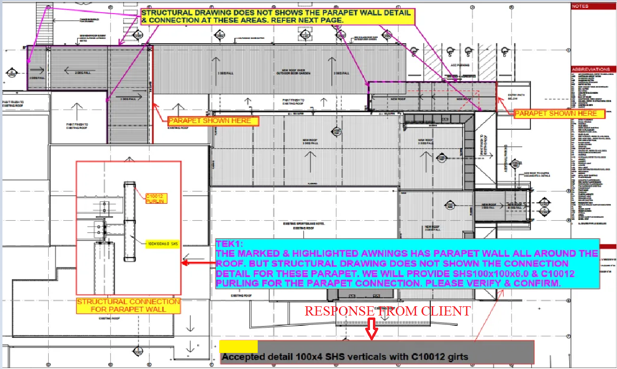
    We always keep our client’s out of trouble from these types of issues.