Month: June 2021

  • Revit Project Data and Parameters Populate in Title sheet


    Input Data

    • Project Details – Does the Revit file allow us to create Project Details. How and where is the data available to read?

    For Project information the details will be added and done in the Manage tab as shown below

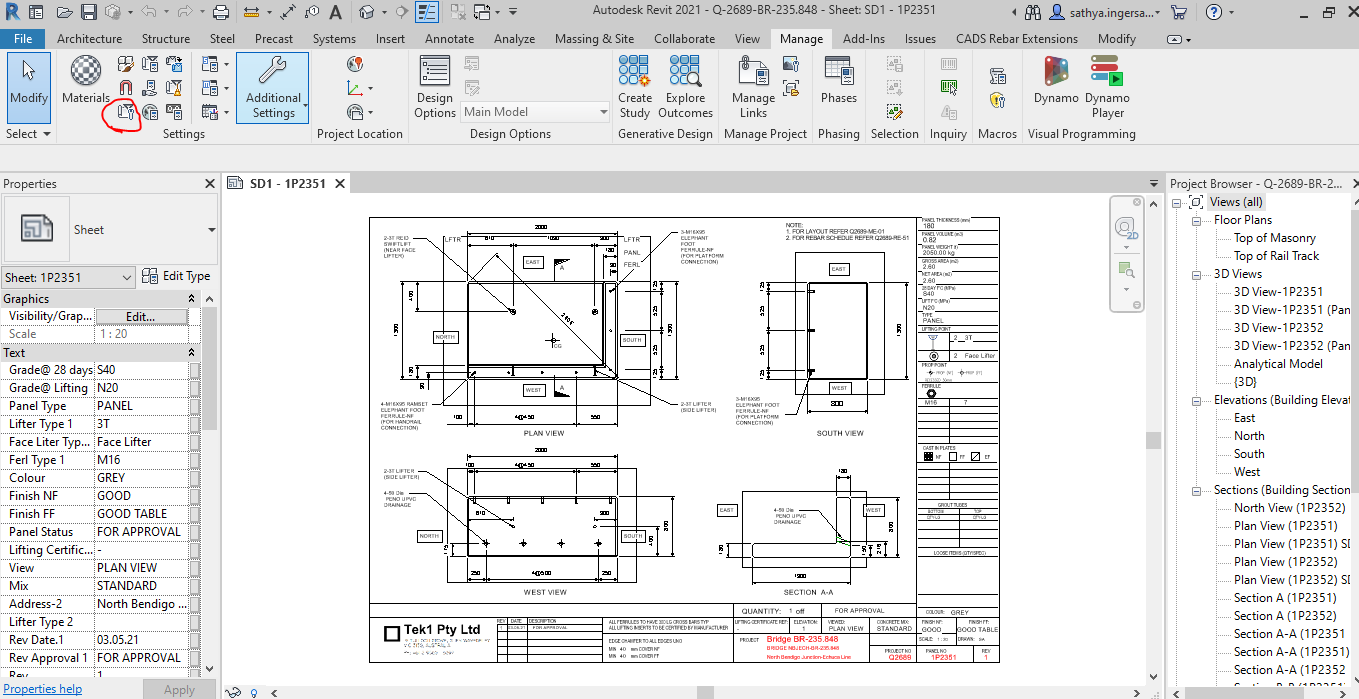
    Step 1: Clicking to manage tab and click on the red clouded region as Project Information


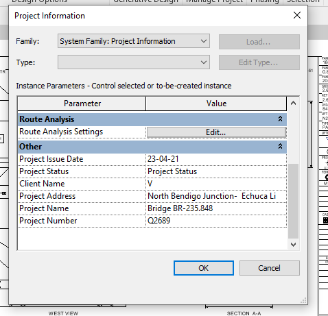
    Step 2: Entering the Data about the Project as Shown above


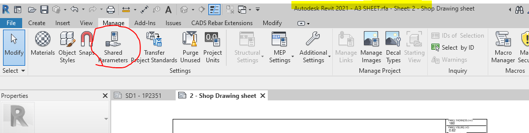
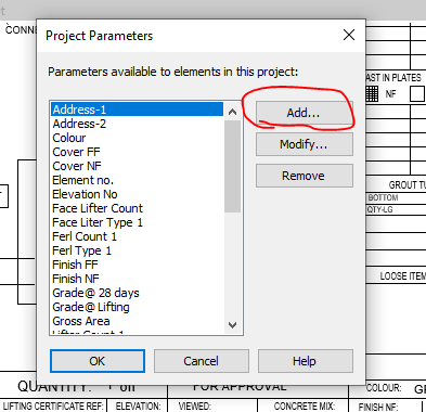
    Step 3: Open the sheet family and click on the Shared Parameter Option in the Manage tab


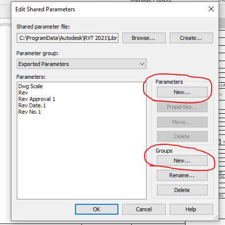
    Step 4: Create the new parameter if needed and Create new group where the parameters are to be called for.


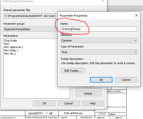
    Step 5: Add the new parameter in the Paremter property. Once parameter done it can’t be edited and it has to be removed and create a new one .


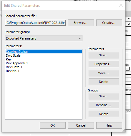
    Step 6: Now the “Drawing Status” Parameter are now called under the Parameter group exported parameter.


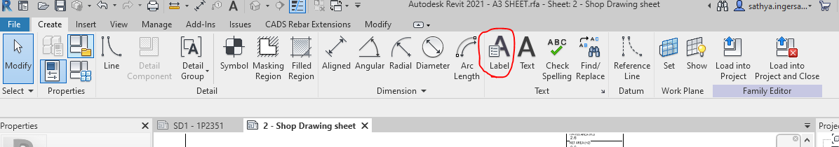
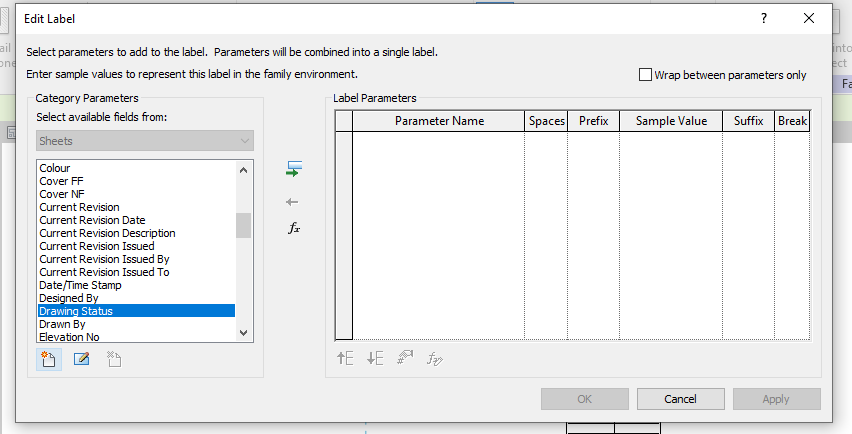
    Step 7: Click the Label Parameter to call the label that are already created in parameter


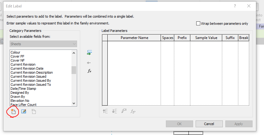
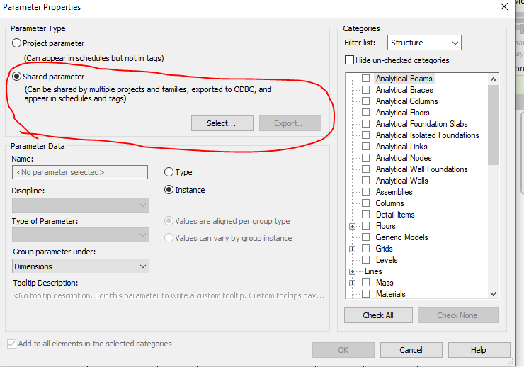
    Step 8: The parameter which was created in shared was not displayed so click on the add parameter to call from the group.


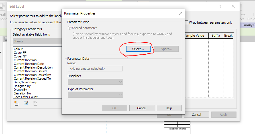
    Step 9: Click on the select button to call the shared parameter group defined.


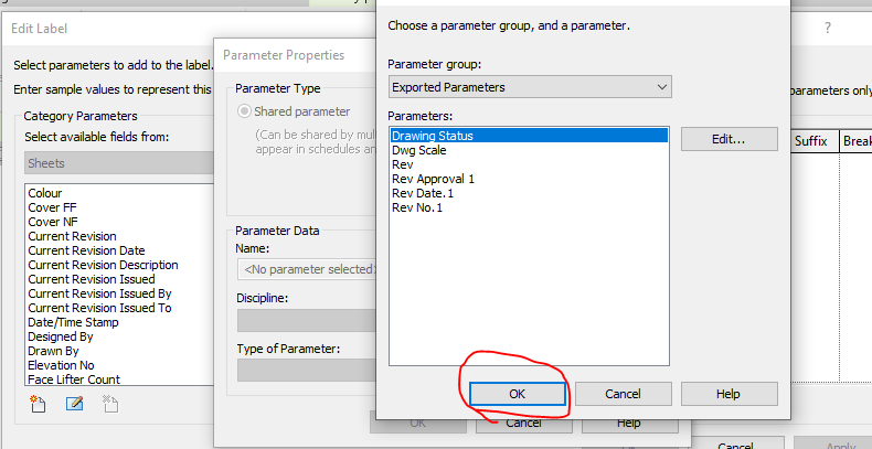
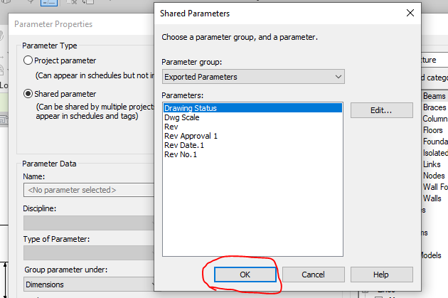
    Step 10: Click on the required parameter to call and click on ok


    Step 11: The parameter which was not available in the list are now generated and called


    Step 12: The parameter which was not available in the list are now generated and called to edit parameter list


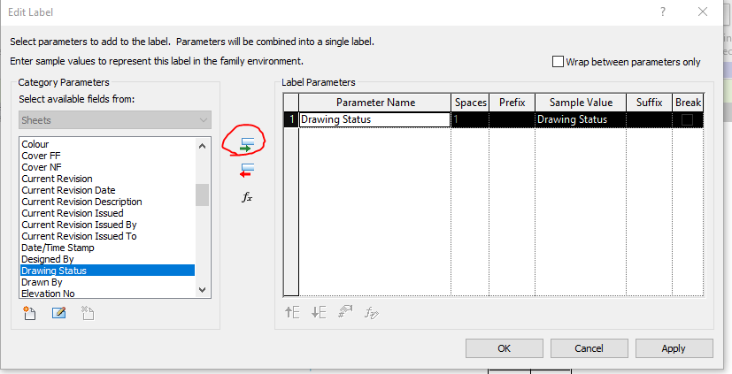
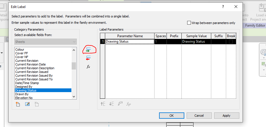
    Step 13: Then click the add parameter lab clouded in red and the following parameter will be added in the label and then click ok.


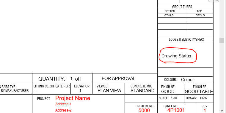
    Step 14: The Label “Drawing Status” was now added in the Sheet Family


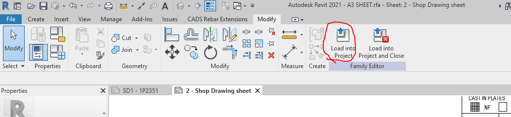
    Step 15: Then click on the “Load into Project“ button to load the Shop Drawing Sheet in the Project.


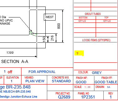
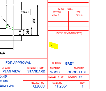
    Step 16: The question mark we highlighted are the Parameter “Drawing Status” and it’s not editable at this stage because this shared parameter was not called in the Project Parameter. To sort this please follow the below steps.


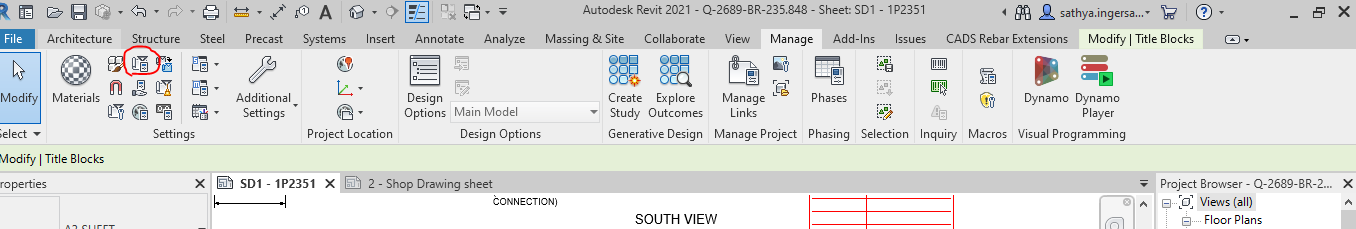
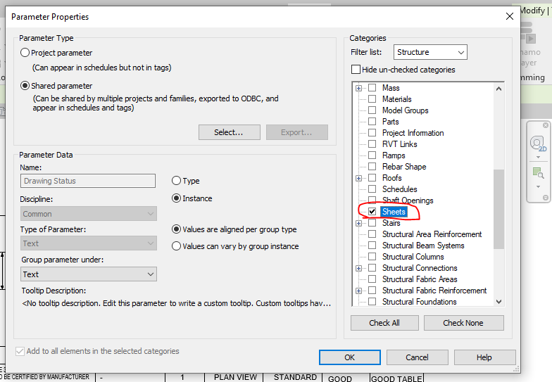
    Step 17: Click on the project parameter to call the shared parameter we defined in Sheet family


    Step 18: Click on to add button


    Step 19: Click on to the shared Parameter and then click select button


    Step 20: Click on the Parameter you defined previously and need to be editable and click ok.


    Step 21: Once the shared parameter are defined on Project Parameter then click the Check box on the right end shown where the parameter to be display in your revit file and then click ok.


    Step 22: Now you can see the question mark colour changes from red to blue which is editable one.


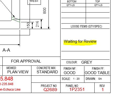
    Step 23: The Parameters are added and edited in the Shop Drawing Title Sheet.


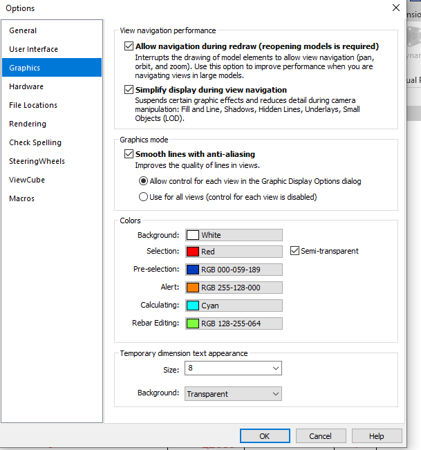
    Idea: If you like to make your visuals to find the parameter is in editable or not editable please do the following thing below

    Go to file tab and click on the option button below and set the graphics by changing the colours as shown below instead of same colour

    Thanks to Koshy, Ben ,Venkat and Parthee for Supporting and guidance .

  • Macquarie Park-Hanging Tube Balustrade

    Macquarie Park-Hanging Tube Balustrade

    This is a complicated project, but it came through. Our Scope was Hanging Balustrade around the Ground Floor Lobby. We need to provide those balustrade in numerous panels. This requires much time to complete the model. But we used our modelling techniques to complete it in a much shorter timeline.

    Design wise, We have faced a lot of problems in this job. Especially, The site was existing, so we weren’t able to transport the fabricated panels to the site. Luckily, we found this issue in the initial stages and we informed this issue to the Client. Hopefully, Gonzo Engineering was able to fabricate the panels on site. So that they avoid a lot of Time & Cost.

    This was drawn by Tek1 (Vignesh), if you want shop drawings for a project you are working on, feel free to call Koshy on: (03) 9560 6397.

    Some of the Model Snaps

    Some of the Site Photos after finishing the works

  • Liverpool Catholic club

    Liverpool Catholic club

    Liverpool Catholic Club is in Hoxton Park Road, Liverpool West NSW 2170

    Author: Ramakrishnan L

    Tek1 has completed this rather complicated project “Liverpool Catholic club”, for Gonzo Engineering, Simon Hatton as the Lead Estimator for Gonzo Engineering & the builder in this instance was Kane Constructions

    The project was complex demanded a very high level of detailing Knowledge. We have put our best guys on this job. They have done wonderfully well in completing this project without a hitch.

    If you want steel shop drawings for a project you are working on, please feel free to call Koshy on: (03) 9560 6397 / +61 3 9560 6397

    For erection video please chk below

    View this post on Instagram

    A post shared by Liverpool Catholic Club (@liverpoolcatholicclub)

    Some of the erection pics & model snaps for this project is given below, Kindly have a look

    LIVER POOL CATHOLIC CLUB SITE ERECTION PIC-01
    LIVERPOOL CATHOLIC CLUB SITE ERECTION PIC-02
    TEK1 MODEL SNAP
    KIDS PLAYING CENTRE CONICAL SECTION

  • Ferrules and bolt length

    Items to take care

    1. Refer Ferrule Catalogue – https://reid.com.au/upload/modules/document_loader/Anchoring_Solutions_Design_Guide_2011.pdf
    2. Check whether ferrule face is flush with concrete or rebated.
    3. Check Thread length in Ferrule
    4. Check total thickness of bolted items including washer.
    5. Make sure that the bolt specified is at least 5 mm less than (WASHER THICKNESS + Plate thicknesses + Rebate in concrete + thread Length)

    Traps

    1. Bolt too long – If thread length in ferrule not taken into consideration
    2. Bolt too short – If washer, Rebate Plate thicknesses not taken into consideration

    Main issue here is the entire length of bolt is decided by the Cut length the modeler provides.

    If proper care is not taken, then there will be a site issue

  • Diamond Creek Netball Pavilion

    Diamond Creek Netball Pavilion

    Author: Pon Dhileepan

    This Diamond Creek Netball Pavilion is a building in Victoria. The pavilion is built next to 8 netball courts. Diamond Creek Netball Association owns this.

    Building Summary:

    The total built up area – 1088 sq.m
    Total steel weight – 40 ton.


    The ground floor of this building is reserved for parking. The first floor has dressing room, 2 change rooms, kitchen , 2 amenities, umpire room, a large multipurpose room etc. The main building in the first is surrounded by corridor from where support could watch the sport. It has a stair and a ramp to access the first floor. The roof is large and is inclined diagonally.

    One special thing about the design is the ramp and first floor slabs are concrete but are laid between perimeter steel members. Refer below image.

    Supply and Schedule:

    This project was undertaken by us during April & May 2020 which was global lockdown period. The project was bit urgent from the client side. After all RFIs, approval submissions, comment implementations, the full pack was submitted by mid of May 2020. We completed it by the desired date even with lesser man power available during lockdown. The project was submitted part by part as requested by the client.


    First supply – Pack for Ramp steel and fence steel
    Second supply – Pack for Stair steel, first floor cast in PFCs and balustrades.
    Third supply – Pack for columns, lintels and roof members.


    A proper coordination between site and detailing team was required as works were undergoing simultaneously. When ramp steel was supplied and they laid concrete, we had to submit the first floor cast in PFCs, cast in plates and balustrades and these must be fabricated before the ramp concrete in done curing. We maintained the schedule properly and no delay happened in the site.

    Some of the model snaps are given below.

    Thanks for reading.

  • Erection Feasibility

    Study erection and fabrication issues from our Take off model.

    With our take off model it is easy to visualize erection problems and fabrication issues. It is a valuable tool for you when you quote for jobs.

  • Identify Gal Items with Color

    Our take off model will shade items in Color for easy identification. Makes easy to check and cost

  • Steel Estimation Reports

    Here is a sample Steel Estimation Report showing, hot rolled, cold rolled and bridging list. If you are accepting the order, then sometimes you will want to make sure that the final drawing does not include extra steel over what you quoted.

    If you take a quote from us for detailing and then award the detailing work to us, then our standard procedure is to check the tender drawings against construction drawings to make sure nothing extra is slipped in.

    Model snap from Take off Model
  • Estimation Bridging List

    Here is a sample of bridging list we provide with Take off. We provide the length and the quantity for accurate estimation. The model also shows the bridging.